Get in touch with Zeyu lntelligent Industrial Company

What a Connector Crimping Machine Actually Does (and Why Crimping Beats Soldering)
At its core, a connector crimping machine applies a precise, repeatable force that deforms a terminal barrel around conductor strands. Strands and terminal metal flow together until the air gaps disappear and the contact turns gas-tight, no oxygen reaches the interface, so no oxide layer can grow and raise resistance over time. That cold weld is why crimping has displaced soldering across most electrical terminations: it adds no heat to the conductor, needs no flux to clean up, and produces a joint in well under a second. Workmanship standards such as NASA-STD-8739.4 even restrict crimped contacts to stranded wire for exactly this reason, solid wire can’t redistribute under compression the way a strand bundle does.
Soldering still has its place for certain board-level work, but for a wire-to-terminal connection it carries real drawbacks. Solder wicks up the strands and create a stiff zone that cracks under vibration, a serious problem in automotive and aerospace wiring. By contrast, a correct crimp keep the strands flexible right up to the barrel. The trade-off is that a crimp has almost no visual margin for error: a joint that look fine can still be under-compressed inside the barrel, which is exactly why the rest of this guide leans so hard on measured quality rather than appearance.
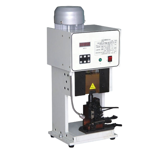
The Four Tiers of Crimping Machines: Hand Tool to Fully Automatic
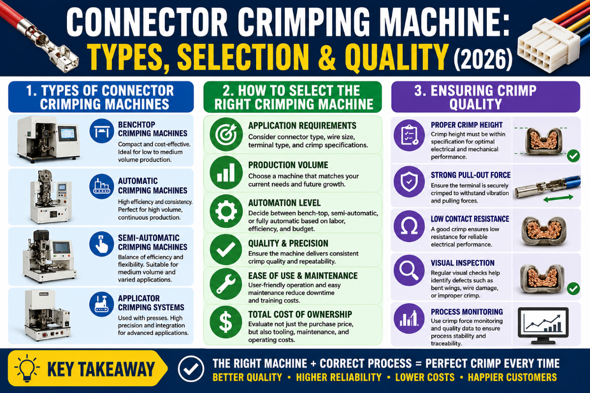
Crimping equipment spans a wide range, and picking the wrong tier wastes money in either direction, overspending on a press for a repair bench, or fighting a hand tool through a production order it was never meant to handle. Most shops fit into one of five steps along a ladder. Each step is rated below on the factors that actually decide fit, using measured attributes instead of marketing tiers. The jump from manual to automatic is largely about the feed and tooling system, patents like CN110603691A describe the interchangeable applicator assemblies that let one powered frame run many terminals.
The Automation Tier Scorecard
| Factor | Hand crimper | Bench manual | Pneumatic press | Semi-automatic | Fully automatic |
|---|---|---|---|---|---|
| Typical output | 50–100/hr | 150–300/hr | 300–600/hr | 600–1,200/hr | up to ~1,800/hr |
| Force source | Hand | Lever/manual | Air | Servo/electric | Servo + feed |
| Consistency | Operator-dependent | Moderate | Good | High | Highest (Cpk-controlled) |
| Crimp force monitor | No | Optional | Optional | Common | Standard, 100% |
| Changeover | Seconds (swap tool) | Minutes (die) | Minutes (applicator) | Minutes (applicator) | Longer (program + feed) |
| Operator skill | High | Medium | Low–medium | Low | Setup only |
| Strip + cut | Separate | Separate | Separate | Often integrated | Integrated |
| Relative cost/crimp | Lowest capital, highest labor | Low | Medium | Low at volume | Lowest at high volume |
| Best fit | Repair, prototyping | Low-volume mixed | Job shop | Small-batch OEM | High-volume harness |
One nuance worth stating plainly: a ratcheting hand crimper in a skilled hand produce fully acceptable crimps. Its ratchet prevent an incomplete cycle, which is the whole point. What changes as you climb the ladder isn’t the ceiling of quality, it’s process control, the ability to guarantee every crimp without a human checking each one.
Matching the Machine to the Connector: Open-Barrel, Closed-Barrel, Ferrule, and Brand Pins
A crimping machine is only as universal as its tooling. Force comes from the press; an interchangeable applicator or die set decides which terminal you can run. Map your connector family first, then choose a machine that accepts the right tooling, buying the reverse order is how shops end up with a press that can’t crimp their main connector.
Can one connector crimping machine handle different connector types?
Yes, but through tooling, not magic. Bench and automatic presses take interchangeable applicators (US patent US 5,661,897 describes the classic applicator with its anvil, caulking jig, and terminal reel), so the same frame can run an open-barrel automotive terminal in the morning and a closed-barrel ring lug in the afternoon after an applicator swap. What a single machine can’t do is span the full range from 30 AWG signal pins to 4/0 battery lugs, force, stroke, and die geometry differ too much. Most production crews settle on a press family that covers their realistic terminal band and accept that extremes need a second tool.
Common terminal families break down like this:
- ✔Open-barrel (DuPont, JST, Molex, Deutsch, Delphi, TE): U- or B-shaped tabs that fold over the conductor and a second set over the insulation, on contact pitches from about 2.5 mm down to 1.0 mm. The OEM workhorse; needs precise applicator alignment.
- ✔Closed-barrel (ring, spade, butt splices): a pre-formed tube the wire enters; crimped with a nest-and-indenter die.
- ✔Ferrules: wire-end sleeves for stranded conductors entering screw terminals; crimped square, hex, or trapezoidal.
- ✔Lugs and large cable: battery and power terminals from 8 AWG to 4/0, usually hydraulic or heavy pneumatic.
- ✔Solar MC4 and coax: specialty geometries with dedicated dies; rising in volume with solar and RF builds.
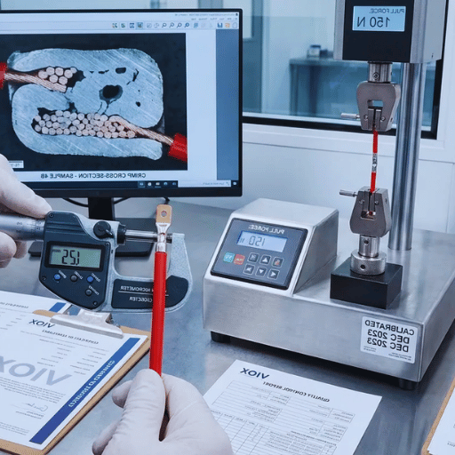
Crimp Height, Pull-Out Force, and Compression: The Crimp Integrity Triangle
Three measurements decide whether a crimp is sound, and they aren’t independent, move one and the others react. We call this the Crimp Integrity Triangle: crimp height, pull-out force, and conductor compression. Understanding how they pull against each other is the difference between a shop that measure crimps and one that guesses at them.
Crimp height is the compressed height of the conductor barrel, measured with a micrometer, not calipers, because the tolerance is tight, terminal makers typically specify it to within roughly 0.02 mm, and it’s the single most controllable indicator on the machine, which is why it’s read with a micrometer resolving to 0.001 mm rather than calipers. Conductor compression is the result: a sound crimp compresses the strand bundle to roughly 75–85% of its loose cross-section, a reduction of about 15–25%, with tooling makers such as Mecal targeting a 17–24% band for open barrels, on a small terminal that can mean only 0.1–0.3 mm of barrel travel between a good crimp and a crushed one. Cut a crimp in cross-section and a good one look like a honeycomb of strands with no voids. Pull-out force is the proof test, how hard you can pull before the wire leave the terminal.
Minimum pull-out force by wire size (pounds), by standard
| AWG | SAE AS7928 | MIL-T-7928G | UL 486A | DIN 41611/3 | NASA-STD-8739.4 |
|---|---|---|---|---|---|
| 30 | 2.1 | — | — | — | — |
| 22 | 15 | 15 | 8 | 11.1 | 13 |
| 20 | 19 | 19 | 13 | 17.1 | 21 |
| 16 | 50 | 50 | 30 | 39.8 | 41 |
| 12 | 110 | 110 | 70 | 92.1 | 103 |
Compiled from published UL 486A-B, MIL-T-7928G, SAE AS7928, and NASA-STD-8739.4 acceptance tables. Always confirm against the current standard and your terminal spec.
Here’s where most buyers get it wrong. Believing that a tighter crimp is a stronger crimp is, flatly, false. As you reduce crimp height, pull-out force climbs, but only to a peak. Push past it and the force falls, because the dies begin shearing the very strands they’re meant to hold. One crimp engineer at Wiring Harness News put it as plainly as anyone: it’s like holding cooked noodles, too loose and some slip out, too tight and you crush them until they break in your hand. In practice the usable window between under- and over-crimp can be under 0.05 mm of crimp height. That sweet spot is a window, not a maximum.
“A pull test that passes does not prove a good crimp, only a not-terrible one. We treat minimum pull force as a floor and put crimp height under SPC, because that is the number that moves before pull force ever drops.”
That instinct is backed by hard data. In NASA testing of crimped contact-wire pairs, most samples exceeded their minimum pull-force requirement by more than 100%, averaging at least 182% of the minimum (NASA NTRS, 2022). In other words, the published pull-force minimums are coarse acceptance floors, not fine quality discriminators. A crimp that clears the floor by a wide margin can still hide a creeping crimp-height drift. That’s why production lines trend crimp height and cross-section, and treat the pull test as a backstop.
How to Read a Crimp: A Field Guide to the 9 Most Common Crimp Defects
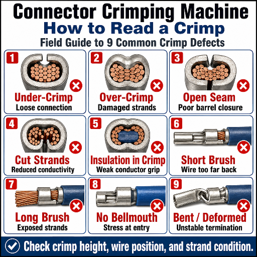
When a crimp fail an audit, the defect usually traces to one of nine patterns. Use this field guide to move from symptom to root cause to fix, most point back to tooling setup or a drifting crimp height rather than the operator. Several of these faults are now caught automatically: patent US 2012/0137486 A1 describes a force sensor that flags a bad crimp from the shape of its force-versus-stroke curve.
| Defect type | What you see | Root cause | Fix |
|---|---|---|---|
| Under-crimp | Loose strands, high crimp height | Insufficient force; height too high | Lower crimp height to spec; verify force |
| Over-crimp | Flattened barrel, cut strands | Crimp height too low; wrong die | Raise height into the 75–85% band |
| No / oversized bellmouth | No flare, or excessive flare at barrel ends | Tool misalignment; worn anvil | Realign applicator; replace anvil |
| Off-center crimp | Barrel folded to one side | Terminal feed/positioning off | Reset feed and locator |
| Insulation in conductor barrel | Jacket trapped under conductor crimp | Strip length too long; bad locating | Correct strip length; check seating |
| Bare wire in insulation barrel | Conductor under insulation grip | Strip length too short | Lengthen strip; re-seat terminal |
| Missing / cut strands | Fewer strands than the wire holds | Cutter damage; over-crimp shear | Check blades; raise crimp height |
| Conductor birdcaging | Strands splayed before the barrel | Strands untwisted; feed timing | Adjust strip/feed; pre-twist |
| Cracked terminal plating | Flaking tin/gold at crimp | Over-compression; brittle plating | Reduce compression; verify lot |
One short shop story makes the pattern concrete. A control-panel builder kept failing intermittent-continuity tests on a 20 AWG harness. Those crimps looked perfect and passed a pull test every time. A cross-section finally showed the answer: strip length ran 0.4 mm long, so a sliver of insulation sat under the conductor crimp on about one terminal in twenty. Pull force was fine, the insulation doesn’t slip, but contact resistance wandered. Fixing it cost nothing: a strip-length adjustment. Learning it cost a week.
Crimp Quality Standards: IPC/WHMA-A-620, UL, and Pull-Force Testing
If you buy or sell crimped assemblies, three standards frame the conversation, and naming the right one in a purchase order removes most quality arguments before they start. They overlap but don’t cover the same ground, so it pays to know where each applies.
How do you test crimp quality?
Through three layers. First, crimp height measured with a micrometer against the terminal maker’s spec, the daily control. Second, the pull test (tensile test), judged against IPC/WHMA-A-620 acceptance criteria; in common production practice that means pull-testing at least the first and last piece of a run, while high-reliability Class 3 work often adds crimp force monitoring on every crimp. Third, periodic cross-section (micrograph) analysis, which most automotive quality plans require on a first article and after any tooling change, it’s the only method that proves the gas-tight compression directly. Pull and crimp-height together catch the day-to-day; the micrograph proves the metallurgy.
Here’s the standards landscape, briefly:
- ✔IPC/WHMA-A-620 Rev F (2025)the current acceptability standard for cable and wire-harness assemblies, published October 2025 to supersede Rev E. Rev F brings updated crimp pull-force tables and cross-section criteria and refines what counts as a process indicator versus a defect across Class 1/2/3.
- ✔UL 486A-BNorth American pull-off minimums by wire size. Note the scope: it excludes some terminal types such as flat quick-connect tabs and bare or covered ferrules, so its table doesn’t cover every connector you’ll crimp.
- ✔IEC 60352-2:2024the international standard written specifically for solderless crimped connections and their test methods. It is the most direct crimp standard for global supply, though it excludes coaxial crimping.
- ✔SAE, MIL, and NASA-STD-8739.4sector acceptance tables (aerospace, defense, space) that often set higher floors than UL.
When Does Automation Pay Off? The Hand-Crimp Reliability Gap
Most buyers hear the case for a machine pitched on speed, but speed is the weaker half of the argument. Its stronger half is what we call the Hand-Crimp Reliability Gap: the spread in crimp quality between a person and a process under statistical control. Skilled operators can match a machine on any single crimp. What a person can’t do is hold that result across a shift without drift from fatigue, grip, and terminal positioning.
Process capability puts numbers on it. Any process considered safely in tolerance carries a Cpk near 1.67 or higher; an automatic press with crimp force monitoring holds force and height tightly enough to live there, while manual crimping scatters far wider because every cycle depend on a hand. The monitoring itself is well-established engineering, patent US 10,522,960 B2 covers converting crimp pressure into a per-cycle quality signal. Modern lines push further, equipment makers report self-learning monitors that adjust for tool wear and material lot, holding reject rates to a small fraction of a percent, and “defective-crimp-cut” systems physically snip a bad terminal off so it can’t reach the next station. None of that’s available to a pair of pliers.
Practitioners on the DigiKey forum land on the same rule from the other direction: a hand tool is the right answer only if you crimp rarely and can pull-test every joint. Above roughly 500 harnesses a month, the math tips toward a semi-automatic bench applicator on labor cost alone, before you count the scrap a monitored process avoid.
How to Choose a Connector Crimping Machine: A 7-Point Selection Checklist
Once the tier is clear, the machine choice come down to seven questions. Work through them in order; the first three eliminate most of the catalogue before price ever enters.
- 1.Wire and terminal range. Does the press cover your real AWG band and barrel sizes, with stroke and force to match? Extremes (fine pins, 4/0 lugs) usually need a second machine.
- 2.Terminal compatibility. Will it accept applicators or dies for your actual connectors, Molex, JST, Deutsch, MC4, ferrules, and are those applicators available without a long lead time?
- 3.Throughput vs. mix. Match output to demand, but weight changeover time heavily if you run many short jobs.
- 4.Applicator and die system. Quick-change, repeatable tooling pays back every changeover. Confirm crimp-height adjustment is fine and lockable.
- 5.Crimp force monitoring. For Class 2/3, treat CFM as standard, not an option, it’s what turns the press into a controlled process.
- 6.Safety and guarding. A powered crimp press is a point-of-operation hazard; OSHA 29 CFR 1910.212 requires guarding that keeps hands clear of the crimp zone. Check the guard, two-hand or light-curtain controls, and documentation before buying.
- 7.Support and spares. Applicators, anvils, and monitors wear. Confirm spares, calibration, and service coverage in your region.
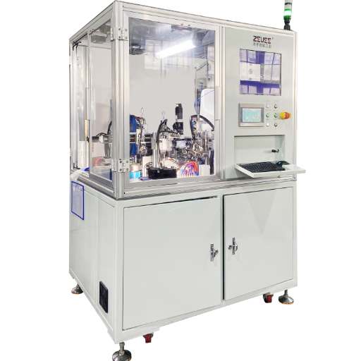
For shops standardizing on a single platform, ZEUEE’s automatic connector crimping machine is built around interchangeable applicators with integrated crimp-force monitoring, which keeps the same frame usable as your terminal mix changes.
Industry Outlook: EV Harnesses, 800V Architectures, and AI Crimp Inspection
Two forces are reshaping connector crimping through the rest of the decade, and a buyer planning a 2026 capital purchase should weigh both. First comes volume and complexity from electrification. As automakers move to 400V and 800V architectures, conductor count and circuit variety climb, and market analyses project the EV wiring-harness automation segment growing at a double-digit annual rate into the 2030s. Rising labor cost in traditional assembly regions is pushing Tier-1 suppliers toward automated cutting, stripping, and crimping that was optional a decade ago.
Inspection moving upstream is the second force. AI vision systems now read a crimp from several angles against a learned “golden sample,” catching position and geometry faults in real time rather than after the fact, and crimp force monitors increasingly tie into MES and predictive-maintenance dashboards, an extension of the force-and-frequency monitoring described in patents such as US 2012/0137486 A1. It’s worth keeping this in proportion, though: a 2024 engineering review notes that the industry hasn’t yet brought vision systems to the point of fully or partially robotizing wire-harness assemblythe wires are too deformable. So the near-term reality is sharper automation of the discrete cut-strip-crimp step and the inspection around it, not a lights-out production line. If you’re buying now, prioritize a machine whose monitoring can feed your quality system; that’s the capability that will still matter in five years.
Frequently Asked Questions
Q: What is the difference between a crimping tool and a crimping machine?
View Answer
A crimping tool is hand-powered — a plier or ratcheting crimper that depends on the operator’s grip and technique for force. A crimping machine adds a powered force source (pneumatic, hydraulic, or servo-electric) plus repeatable tooling and, often, crimp force monitoring. In practice, the difference is process control: the machine reproduces the same crimp thousands of times, while a hand tool varies with the person holding it.
Q: Can one connector crimping machine handle different connector types?
View Answer
Within a sensible range, yes. A bench or automatic press takes interchangeable applicators or dies, so one frame can run open-barrel, closed-barrel, and ferrule terminals after a tooling swap. What it cannot do is span the whole spectrum from fine signal pins to heavy battery lugs — force and die geometry differ too much, so extremes usually need a dedicated second machine.
Q: What is crimp height and why does it matter?
View Answer
Crimp height is the compressed height of the conductor barrel after crimping, measured with a micrometer against the terminal maker’s specification. It matters because it is the most direct, controllable indicator of compression — and because it drifts before pull force does. Tolerances can be as tight as ±0.013 mm, so production lines trend crimp height as their daily quality control rather than relying on pull tests alone.
Q: How do you test the quality of a crimped connection?
View Answer
Three layers, and good shops use all of them. Crimp height with a micrometer is the daily control, checked against the terminal spec. The pull (tensile) test is the strength proof; IPC/WHMA-A-620 asks for it at minimum on the first and last piece of a run, and Class 3 work often monitors crimp force on every crimp. Cross-section analysis, where a crimp is cut, polished, and examined under a microscope, is the only method that directly confirms the gas-tight compression — most automotive plans require it on a first article and after any tooling change. Remember that minimum pull-force values are floors: NASA testing found crimps routinely exceed them by 80% or more, so a passing pull test alone does not prove a well-controlled process.
Q: Is crimping better than soldering for electrical connectors?
View Answer
For wire-to-terminal connections in equipment that moves or vibrates, crimping is generally preferred and has replaced soldering in most such applications. A correct crimp forms a gas-tight cold weld without heating the conductor, and it keeps the wire flexible right up to the barrel. Solder, by contrast, wicks into the strands and creates a stiff transition that can crack under vibration — a known failure point in automotive and aerospace wiring. Soldering still suits some board-level and very-fine-wire work, but for connectorized wiring a properly controlled crimp is more durable and far faster to produce.
Q: How much does an automatic crimping machine cost?
View Answer
As of 2026, prices vary widely by tier — bench presses sit at the low end, while fully automatic cut-strip-crimp lines with monitoring run far higher. Request a quote against your terminal mix and volume, since applicator count drives much of the cost.
About This Guide
This guide was prepared by the ZEUEE engineering team, which designs automated connector crimping and wire-harness assembly equipment and has supported crimp-quality setups for manufacturers across more than 30 countries. The pull-force, crimp-height, and standards figures here are drawn from published IPC, UL, IEC, SAE, and NASA acceptance criteria and cross-checked against our own production experience.
References & Sources
- IPC/WHMA-A-620 Requirements and Acceptance for Cable and Wire Harness Assemblies (Rev F, 2025)IPC International
- UL 486A-486B Wire ConnectorsUL Standards & Engagement
- IEC 60352-2:2024 Solderless Connections, Crimped ConnectionsInternational Electrotechnical Commission
- NASA-STD-8739.4 Workmanship Standard for Crimping, Cables, Harnesses, and WiringNASA
- Crimp Pull-Force Test Data StudyNASA Technical Reports Server (2022)
- 29 CFR 1910.212 General Requirements for All MachinesU.S. OSHA
- US 2012/0137486 A1, Crimping Apparatus with Crimp Quality MonitoringUSPTO
- US 5,661,897, Applicator for Terminal Crimping MachineUSPTO
- Pull-Force Testing Crimped WiresASSEMBLY Magazine
- Crimp Quality ImprovementWiring Harness News