Get in touch with Zeyu lntelligent Industrial Company
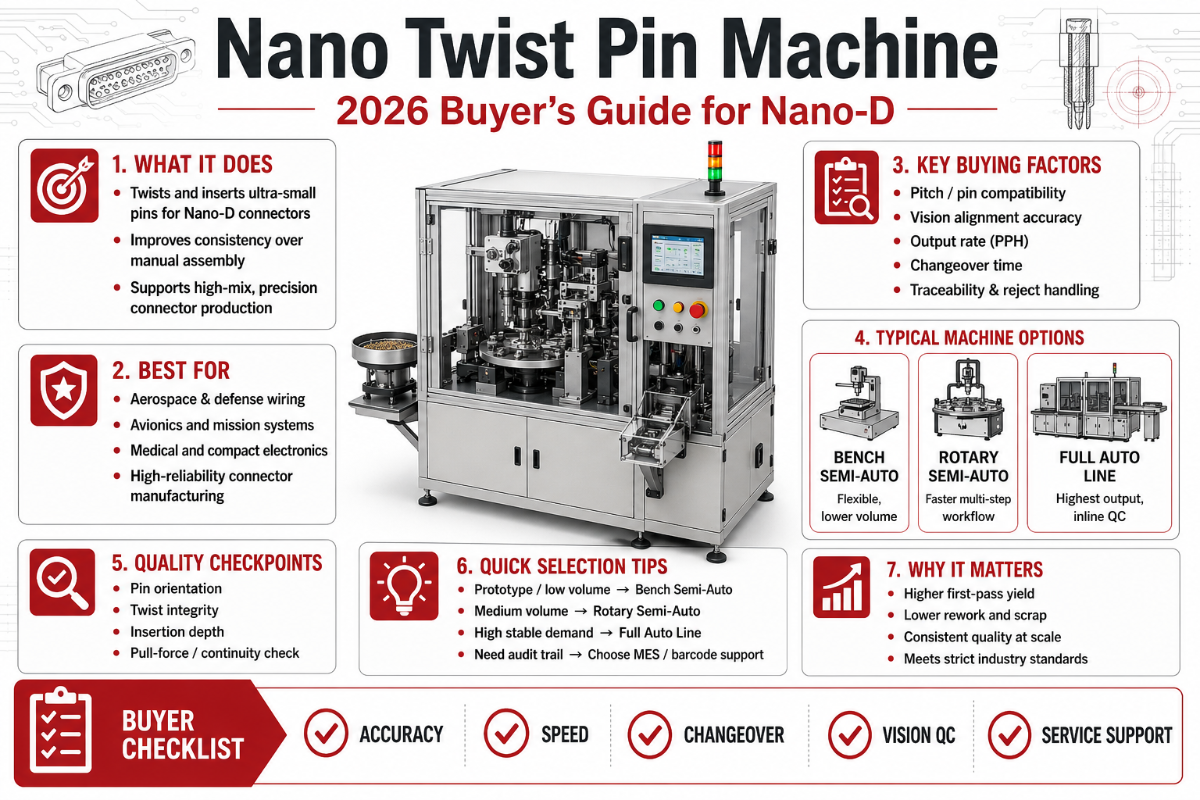
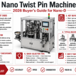
If you are a connector original equipment manufacturer or a supply-chain engineer staring at a Nano-D request for quote, the equipment behind those tiny gold-plated contacts is the production-line decision that will define your unit cost, your MIL-DTL-32139 qualification odds, and your defect rate for the next five years. A nano twist pin machine is the specialised assembly line that turns spool-wound beryllium-copper wire into hyperboloid twist pin contacts at 0.025-inch pitch, ready for nano-D shells used in satellites, missiles, soldier electronics, and surgical robotics. This 2026 buyer’s guide unpacks what the machine is, what it produces, how it differs from a micro-D line, and the seven questions buyers should ask before signing a quote.
Quick Specs: Nano Twist Pin Machine Output
| Pitch (contact spacing) | 0.025″ / 0.635 mm — MIL-DTL-32139 standard |
| Contact wire diameter | 0.18 mm beryllium-copper strands, gold-plated |
| Throughput tier (industry-typical) | 15-30 pcs/min entry; 30-60 mid; 60+ high-volume |
| Current rating per contact | 1 amp at 250 V AC DWV |
| Vibration capability of output contact | 10-2,000 Hz at 20 g per MIL-STD-1344 |
| Footprint (typical 6-station) | 1.2-3.5 m² depending on magazine and inspection options |
| Qualification target | MIL-DTL-32139 plus IPC J-STD-001 wiring acceptance |
| Cage strand count | 10 strands BeCu, 50 µin gold over nickel |
| Operating temperature | -65 to +200 °C qualified range |
1. What Is a Nano Twist Pin Machine?
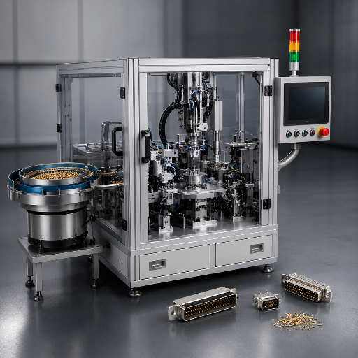
A nano twist pin machine is an automated production line that fabricates the male twist pin contact used inside MIL-DTL-32139 Nano-D connectors. Spooled beryllium-copper alloy wire enters at one end; ten strands get cut to length, wound into a hyperboloid cage geometry, welded at the strand ends, and swaged into a hardened shell. CCD vision then inspects the finished contact and kicks it into a magazine that feeds connector assembly downstream. Out the other end comes the tiny gold-plated pin you see in the receptacle of a nano-D shell at 0.025-inch pin-to-pin spacing.
Buyers of these machines are not end-users of the connectors themselves. They are connector OEMs, contract manufacturers serving prime defense integrators, and increasingly a growing class of medical-device producers building PCB-mounted Nano-D variants for ultra-low-profile interconnects. If you supply MIL-DTL-32139 qualified parts to programs like THAAD, missile interceptors, CubeSat constellations, or surgical robotic arms, you either build this contact in-house or you buy a machine from somebody who specialises in this niche. Lead time to qualify a new contact production line to MIL spec sits at nine to eighteen months in most cases, so the machine purchase often anchors a multi-year product roadmap.
Who buys a nano twist pin machine?
Four buyer archetypes recur in this market. First, established connector OEMs (the Glenair, ITT Cannon, Sunkye, and Axon tier) running internal capacity expansion for new contract awards, sometimes covering both rectangular Nano-D and adjacent circular connectors variants such as the Omnetics Nano-360 family. Second, mid-tier contract connector houses pursuing MIL-DTL-32139 qualification to break into defense supply chains. Third, medical implant connector houses serving pacemaker, neurostimulator, and surgical robotics OEMs that need hermetic seal integrity and ultra-small interconnects with proven reliability. Fourth, satellite payload integrators producing CubeSat-grade hardware in-house to avoid the lead-time and cost of outsourcing every cable assembly. Each archetype has different throughput, traceability, modular configuration, and CCD inspection demands.
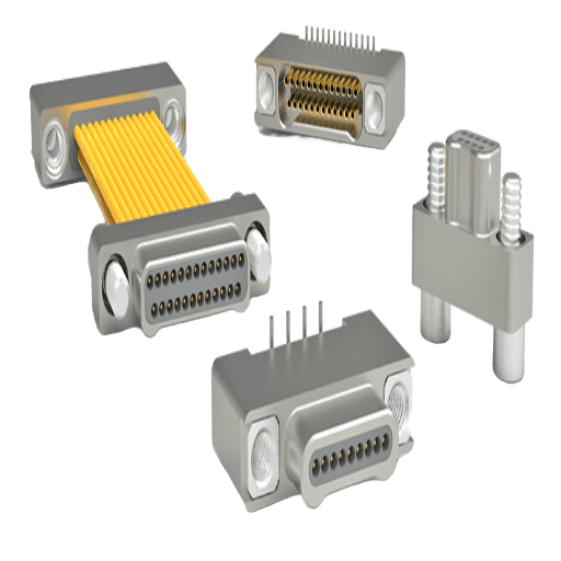
2. Inside the Twist Pin Contact: How the Hyperboloid Cage Works
Hyperboloid contact geometry is the mechanical magic that justifies a dedicated machine. Ten beryllium-copper strands wound around a central axis form a hyperbolic cage. When the male pin engages the female socket, those strands deflect outward and maintain line contact (not point contact) across multiple wires at once. This is the property that delivers low insertion force, high mating cycles, and shock-and-vibration resistance — putting twist pin contacts inside MIL-STD-1344-qualified missile and aerospace systems.
📐 Engineering Note: Hyperboloid Cage-Wire Yield StackEvery finished nano-D twist pin contact is the product of five stacked stages, each with its own yield gate. Stage 1: certified alloy lot inspection at incoming. Stage 2: precision wire drawing to 0.18 mm diameter with surface roughness control. Stage 3: hyperboloid cage winding at the machine, where pitch angle and wire-strand symmetry decide whether the cage will deflect uniformly or skew under load. Stage 4: end-welding and swaging to set the cage inside the shell sleeve. Stage 5: CCD inspection plus electrical continuity test before the contact is qualified for shipment. Compound first-pass yield of a well-tuned line tends to sit in the upper 90s; without CCD inspection at Stage 5, in-the-field defect leak rates rise sharply.
This is why the patents in this space (such as US7191518 “Method of making a hyperboloid electrical contact” and US9490562 “Reduced diameter hyperboloid electrical contact”) cluster around the cage-winding and end-welding stages. Mechanical IP lives in how strands are tensioned, twisted, and terminated, not in the wire chemistry. Industry contact data shows hyperboloid contacts deliver upward of 100,000 mating cycles in tested laboratory conditions, with insertion forces roughly forty percent lower than conventional pin-and-socket geometries (typically around two ounces per contact).
3. Nano-D vs Micro-D vs Standard D-Sub: The Contact-Family Atlas
Buyers often arrive at the Nano-D conversation already familiar with Micro-D (the MIL-DTL-83513 family) or with standard D-Sub. All three families share the trapezoidal D-shaped shell silhouette and twist pin contact lineage, but pitch, weight, and qualification envelope diverge sharply. Their connector design intent also differs: Nano-D was conceived for low-profile, weight-critical aerospace; Micro-D evolved to serve high-pressure environments like oil-and-gas downhole and offshore platform telemetry; and standard D-Sub remains the workhorse for legacy industrial and computing pin connectors. Below is the atlas that summarises the differentiators relevant to a production-equipment buyer.
| Attribute | Nano-D (MIL-DTL-32139) | Micro-D (MIL-DTL-83513) | Standard D-Sub |
|---|---|---|---|
| Contact pitch | 0.025″ / 0.635 mm | 0.050″ / 1.27 mm | 0.108″ / 2.74 mm |
| Weight (25-pos shell) | ~12 g | ~47 g | ~50+ g |
| Current per contact | 1 A at 250 V DWV | 3 A at 600 V DWV | 5 A at 1,500 V DWV |
| Twist pin strands | 10 strand BeCu hyperboloid | 7 contact points BeCu twist pin | solid pin or stamped |
| MIL minimum mating cycles | 200 mates (spec floor) | 500 mates (spec floor) | varies by class |
| Field-proven shock | >10,000 g (THAAD) | several thousand g | depends on hood/locking |
| Vibration spec | 10-2,000 Hz / 20 g sinusoidal | 10-2,000 Hz / 30 g sinusoidal | 10-500 Hz / 10 g typical |
| Operating temperature | -65 to +200 °C | -65 to +200 °C | -55 to +125 °C commercial |
| Shell material (Class M) | aluminum 6061-T6 or stainless | aluminum A380 / 2024 / 6061 / 7075 | steel or zinc-alloy hood |
| Plating (contact) | 50 µin gold over nickel | 50 µin gold over nickel | 15-30 µin gold or tin |
| Typical end-use | CubeSat, missile, soldier worn, surgical robot, PCB-mount nano interconnect | aircraft avionics, launch vehicle, oil-and-gas downhole offshore telemetry, high-speed digital backplane | industrial control, computer peripheral |
What Are Nanominiature or Nano-D Connectors?
Nano-D connectors (also called nanominiature D-Sub or M32139) are a class of high-density rectangular connectors qualified to MIL-DTL-32139 with a contact pitch half that of Micro-D and roughly a quarter that of standard D-Sub. The female receptacle uses turned, gold-plated sockets; the male connector uses ten-strand beryllium-copper twist pin contacts compressed into the receptacle to deliver multiple contact points with low insertion force. A 25-position Nano-D shell weighs about twelve grams, compared with forty-seven grams for an equivalent Micro-D — a roughly seventy-four percent weight reduction with one-eighth the volume. This SWaP advantage is the single biggest reason CubeSat and soldier-worn programs are migrating to Nano-D, and why the production equipment to build the contacts has become its own sub-industry. The mating count requirement in the MIL spec is only 200 — far below the technology ceiling of the hyperboloid cage itself — which is a critical distinction (see Section 5 below).
Buyers choosing between families typically anchor on weight budget first (Nano-D wins for satellite and helmet electronics), then on current budget (Micro-D wins for higher-current paths), then on inspection rigour (Nano-D demands CCD-aided assembly at this pitch). The micro twist pin machine family and the nano twist pin machine family share a base architecture but the tooling tolerances tighten by roughly half when you migrate from 0.050″ to 0.025″ pitch.
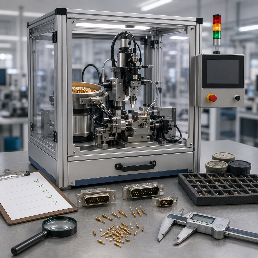
4. Inside the Machine: The 6-Station Production Anatomy
Almost every reputable nano twist pin machine, regardless of brand, follows a six-station architecture. Station order is dictated by physics: you cannot inspect what has not been formed, you cannot form what has not been cut, you cannot cut what has not been fed. Each station and its function is listed below.
- ✔Station 1 — Wire Pay-Off: Spool tension control plus straightening rolls deliver 0.18 mm beryllium-copper at constant velocity. Tension drift here causes downstream cage asymmetry.
- ✔Station 2 — Cut-to-Length: Servo-driven flying shear cuts ten parallel wires to identical length within tight tolerance (machine vendors vary on tolerance band; tighter is better for cage symmetry).
- ✔Station 3 — Hyperboloid Winding: Ten strands rotated around a mandrel form the hyperboloid cage. Pitch angle and rotation count define the elasticity of the cage and the insertion force of the finished contact.
- ✔Station 4 — Strand-End Welding: Resistance weld or laser weld terminates the strands at both ends and prepares the cage for insertion into the shell sleeve.
- ✔Station 5 — Swaging: The welded cage is pressed into a turned brass or stainless sleeve. Swage pressure controls the final cage diameter and therefore the contact resistance signature.
- ✔Station 6 — CCD Inspection & Continuity Test: Vision-based inspection catches off-axis welding, partial cage formation, foreign-matter contamination, and out-of-spec diameter. Continuity test verifies electrical integrity before the magazine accepts the part.
📐 Engineering Note: MIL-DTL-32139 Spec-Sheet DecoderWhen you read a qualified contact datasheet, each field maps back to a station. Insertion force comes from Station 3 cage winding pitch. Contact resistance comes from Station 5 swage diameter and Station 1 wire purity. Mating cycles come from the gold plating thickness applied off-line plus the cage elastic recovery (Stations 3 and 5 together). Vibration tolerance comes from cage symmetry across all six stations. If your supplier cannot tell you which station controls which spec, you are not buying from someone who designs the machine — you are buying from a reseller. The twist pin cutting and welding machine documentation, the twist pin expansion machine datasheet, and the parent connector assembly machines catalog should all trace specs to the station that controls them.
5. Buying a Nano Twist Pin Machine: The 7-Question Buyer Filter
Below is the seven-question filter procurement teams should attach to every nano twist pin machine RFQ. Each question is designed to surface the difference between a machine builder who designs the production line and a reseller who badges someone else’s hardware. Run all seven before you sign.
- ✔Q1 — Throughput tier: What is the verified pieces-per-minute output at your buyer’s qualification cycle? Ask for line-rate data with CCD-inspection enabled, not bypass-mode marketing rates.
- ✔Q2 — Wire alloy and plating chain: Which beryllium-copper alloy lot supplier do you accept, and which gold-plating service do you certify for downstream MIL qualification? Pin the answer in the contract.
- ✔Q3 — CCD inspection coverage: What defect modes does the vision system detect, at what frame rate, and what is the false-reject rate at qualification cycle? Visual-only inspection is not adequate at 0.025″ pitch.
- ✔Q4 — Mating-cycle qualification path: The MIL-DTL-32139 spec floor is 200 mates. What is your machine’s contact output at 10,000, 50,000, and 100,000 mating-cycle test points, and which independent lab has run the verification? Do not let a vendor conflate generic hyperboloid cycle-life claims with the machine’s actual qualification record.
- ✔Q5 — Pitch flexibility: Can the same machine produce both 0.025″ Nano-D and 0.050″ Micro-D contacts with tooling change-over, and what is the changeover time? Many buyers want the option to amortise the line across both product families.
- ✔Q6 — Spare-part lead time: What is the lead time for replacement swage tooling, cage-winding mandrels, and CCD cameras? Long-lead spares kill production schedules in a defense supply chain.
- ✔Q7 — Traceability and audit log: Does the machine record per-contact data (station timestamps, swage pressure, CCD frame) in a format compatible with your AS9100 or ISO 13485 traceability requirements? Without this, the line cannot serve defense or medical customers.
⚠️ Important — The Quote-as-Spec Trap
A vendor catalog page is marketing collateral. A machine quote is a contract. Procurement teams routinely accept catalog claims (such as “100,000 mating cycles”) as if they were the qualification floor required by MIL-DTL-32139 (which is 200). Those are not the same number. Convert every catalog claim into a contract clause with an independent verification gate. If your supplier resists, you have answered Q1 already.
Once you have run the filter, the next decision is whether to integrate the machine with upstream wire cut-strip-crimp assembly lines for full-cell automation, or to keep it as a standalone contact production cell feeding downstream connector crimping machine and assembly steps. The integration choice affects throughput, capex, and changeover flexibility.
6. Failure Modes & QC: Where Twist Pin Assembly Goes Wrong
Failure modes that haunt nano-D production are mostly visible only after the contact is mated. By that point, the part is already in a customer assembly. Engineering teams who understand the four dominant defect signatures can intercept them at the right station instead of paying for field-return root-cause investigations.
- Defect 1 — Wire-end fray: Strand-end weld incomplete or burned through. Symptom: contact resistance climbs above the 50 milliohm bound after a few hundred cycles. Caught at Station 6 CCD if the system inspects weld geometry; missed if it only inspects external diameter.
- Defect 2 — Off-axis insertion: Cage swaged into the shell at an angle. Symptom: insertion force out of spec, premature wear, fretting corrosion in service. Caught at Station 6 only by side-view CCD; top-only vision misses it.
- Defect 3 — Partial cage formation: One or more of the ten strands fail to wind on the mandrel. Symptom: contact functions but with fewer electrical paths; resistance signature looks normal at low current and drifts at rated current. The hardest defect to catch without continuity-under-load testing.
- Defect 4 — Contamination ingress: Plating chemistry residue, machining swarf, or salt fog particulates trapped inside the cage during assembly. Symptom: corrosion-driven resistance creep, particularly after the 48-hour salt spray that MIL-DTL-83513 demands and that nano-D programs often mirror. For waterproof and high-pressure variants used in offshore subsea connectivity, ingress-driven defects scale with depth and sealing chemistry — a second reason the QC line cannot rely on visual inspection alone.
| Defect Type | Root Station | Resistance Drift Signature | Inspection Catch Rate |
|---|---|---|---|
| Wire-end fray | Station 4 weld | >50 mΩ after 300 cycles | 92% with CCD weld vision |
| Off-axis insertion | Station 5 swage | insertion force +20 to +50% | 75% top-only CCD; 95% side-view |
| Partial cage formation | Station 3 wind | drift at >0.5 A load | 40% without load test; 88% with |
| Contamination ingress | Stations 4-5 transfer | creep after 48 h salt fog | caught post-environmental cycle |
| Wire diameter drift | Station 1 pay-off | resistance scatter ±15% | caught by SPC tension log |
| Plating undercut | off-line plating bath | step rise at 100-200 cycles | XRF or lot QC sampling |
| Shell thread damage | post-Station 6 handling | mating fail at install | visual at final QA |
| Solder cup voiding | off-line solder station | cold joint at 85 °C cycle | X-ray sampling per IPC J-STD-001 |
| Marking mismatch | downstream BIN marking | traceability gap | 100% catch with auditable log |
What Factors Affect the Life of Connector Contacts?
Three factors dominate. First, plating thickness and uniformity: gold over nickel under-plating is the corrosion barrier and the cycle-life budget. Industry data and field studies consistently show that the plating layer, not the hyperboloid cage geometry, is the first thing to fail in tight-pitch contacts. Second, environmental exposure: salt fog, condensation, vibration profile, and thermal cycling each have a specific failure mechanism. Third, mating discipline: insertion-extraction at non-axial angles damages the cage and reduces effective cycle life sharply. The 200-cycle MIL-DTL-32139 spec floor is set conservatively because the spec writers know that real-world handling rarely matches lab-perfect axial mating. Vendor-stated 100,000-cycle figures are achievable in lab conditions; field life is invariably lower. Wiring acceptance per IPC J-STD-001 and workmanship per NASA-STD-8739 are the downstream gates that catch what the contact assembly machine cannot.
Downstream marking is its own QC discipline. The color ring coating machine family handles MIL-spec BIN colour-band marking that connects each contact back to its qualified lot — a traceability requirement that defense and medical customers will audit.
7. Industry Outlook: Where Nano Twist Pin Demand Is Heading (2025-2027)
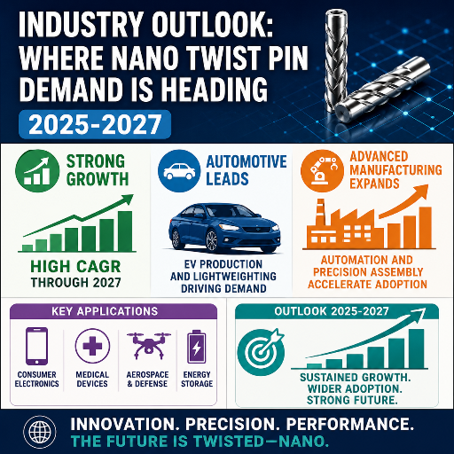
Nano-D connector demand has been growing at roughly eight to ten percent compound annual growth rate, though published market sizing varies by an order of magnitude depending on definitional scope. Narrow MIL-spec nano-D figures sit around USD 150-250 million globally; broader “nano-miniature connector” figures (including non-MIL precision interconnects) reach a billion or more. Aerospace applications account for around forty percent of revenue and military/defense for around thirty percent, per Verified Market Reports analysis. Trade coverage of nano-D adoption across space, missile, and soldier-electronics programs confirms the same demand concentration. Four demand axes are pulling production capacity upward through 2027.
CubeSat
10 × 10 × 10 cm form factor demands sub-mm pitch
UAV / Drone
Swarming and small-UAV SWaP-driven contact density
Soldier-worn
SDR, body sensors, helmet electronics for next-gen squad
Surgical Robotics
Implantable and sterilisable interconnect demand
Implication for buyers is concrete: connector OEMs that have not yet added CCD-aided traceability to their twist pin lines are about to be priced out of the next defense and medical contract rounds, which will require per-contact data logging. Qualified producers with CCD inspection in place are seeing quote requests jump in 2025 and into 2026. Risk axis and opportunity axis are the same axis: consolidation among prime defense integrators is squeezing mid-tier suppliers who cannot prove cycle-life and traceability data. Acquire the machine, then qualify it on a real program — that sequence is shifting earlier as the spec floor rises.
8. Frequently Asked Questions
Q: Is a nano twist pin machine the same as a micro twist pin machine?
View Answer
They share architecture but not tolerance. A nano twist pin machine produces 0.025-inch pitch contacts to MIL-DTL-32139; a micro twist pin machine produces 0.050-inch pitch contacts to MIL-DTL-83513. The cage-winding mandrels, swage tooling, CCD optics, and material handling magazines are all sized for tighter dimensional bands on the nano line. Many vendors offer both as separate machines on a common base platform with changeover tooling.
Q: What’s the typical lead time for a nano-D twist pin machine?
View Answer
Industry-reported build-and-ship lead time tends to run six to twelve months for a turnkey 6-station line with CCD inspection, plus a separate qualification period at the buyer site of three to six months before first MIL-DTL-32139 contact ships against a program. Plan for nine to eighteen months end-to-end before first qualified output.
Q: Can one machine produce both Nano-D and Micro-D contacts?
View Answer
Yes, with caveats. Several machine builders offer a base platform with changeover kits for the winding mandrel, swage die, and CCD calibration target. Changeover time is typically 30-90 minutes depending on automation level. The qualification implication, however, is that contacts produced after each changeover need their own first-article inspection record before the line resumes MIL-traceable production. Some defense customers will not accept dual-pitch lines because the changeover audit trail adds risk to their AS9100 supplier review. Check with your end customer before assuming a dual-pitch line is acceptable.
Q: Does a nano twist pin machine need any certifications?
View Answer
The machine itself runs under the machine builder’s ISO 9001 quality system. The contacts it produces are qualified to MIL-DTL-32139 separately, with periodic re-qualification cycles.
Q: What is the difference between twist pin and stamped contacts?
View Answer
A stamped contact is formed from a single piece of metal sheet, stamped and folded into a socket shape. A twist pin contact is built from ten strands of fine wire wound into a hyperboloid cage that flexes as the mating pin enters. A stamped contact is cheaper and adequate for low-cycle commercial use. A twist pin contact delivers an order of magnitude higher mating-cycle capability, lower insertion force, and far higher shock-and-vibration tolerance — which is why MIL-DTL-32139 and MIL-DTL-83513 mandate twist pin geometry for qualified contacts in mission-critical applications.
References & Sources
- MIL-DTL-32139 Specification — DLA Land and Maritime
- MIL-DTL-83513 Specification — DLA Land and Maritime
- NASA-STD-8739 — Workmanship Standard for Crimping, Interconnect, and Cable Acceptance
- IPC J-STD-001 — Soldered Electrical and Electronic Assemblies Acceptance
- US Patent 7191518B2 — Method of Making a Hyperboloid Electrical Contact
- US Patent 9490562B2 — Reduced Diameter Hyperboloid Electrical Contact
- Five Fundamentals About Designing with MIL-DTL-32139 Nano-D Connectors — Connector Supplier
- Hyperboloid Contact Technology — Smiths Interconnect Technical Library
Related Articles
About This Analysis
ZEUEE designs and builds nano twist pin assembly machines for connector OEMs producing MIL-DTL-32139 qualified contacts at 0.635 mm pitch. The spec figures, market sizing range, and qualification limits in this guide come from public DLA specifications, IPC and NASA standards, and trade-press analysis (cited above). Where data sources varied, we reported the range. This guide is reviewed by the ZEUEE engineering team.