Get in touch with Zeyu lntelligent Industrial Company
Pin & Socket Contact Quality Assurance
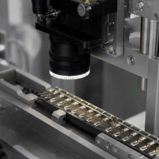
Connector Inspection Automation: Pin & Socket Contact Vision Inspection Machines
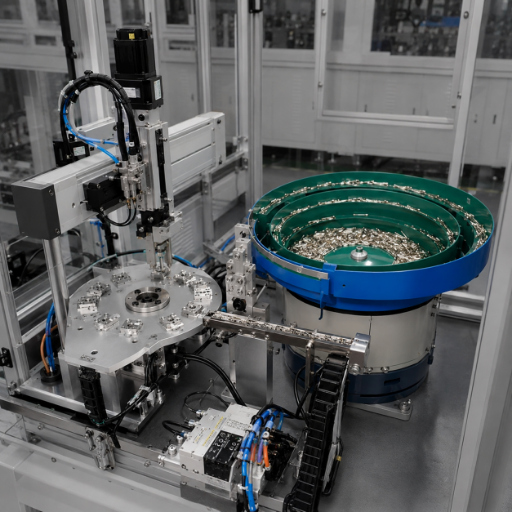
Connector inspection automation puts a multi-CCD machine vision station between your contact-assembly line and your shipping dock, so bent pins, missing contacts, burrs and contamination get caught at the source instead of on a customer’s board. ZEUEE engineers and builds these systems for connector makers who can’t afford a quality escape.
100%
inline inspection vs sampling
<25
DPPM automotive world-class target
150+
R&D patents behind ZEUEE builds
Inspects
pin & socket contacts, terminals, connector housingsVision
multi-CCD cameras + telecentric/dome lightingDefects caught
bent/missing pin, coplanarity, burr, plating, contaminationCoplanarity sensitivity
down to <0.1 mmLine speed
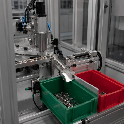
configurable to high-rate contact productionSorting
automatic pass/fail reject + data loggingThe Hidden Cost of Quality Escapes in Pin & Socket Contact Production
A single bent pin that ships look cheap on the production floor and ruins you in the field. Once a defective contact reach a customer’s assembly, the failure no longer costs you a scrap part, it costs a line stoppage, a warranty claim, and in automotive or aerospace work, a share of a recall. Suppliers’ share of recall costs reached 15–20% by 2018, and supplier-named recall notices have doubled since 2013. Beyond the recall itself, an escaped contact drive downtime on the customer’s line, added maintenance, and in safety-critical builds a genuine reliability problem that erodes trust faster than any price advantage can win it back. That defect-escape interval, the gap between when a bad contact is made and when someone finally catches it, is the single most controllable number in that math.
Manual and sampling inspection leave that interval wide open. One vehicle-seat maker checking 2,000 seats per day by hand couldn’t hold a consistent standard on the connectors before it moved to 100% inline vision. Pin and socket contacts make the problem worse than most parts: the defects that matter, a 0.3° bend, a coplanarity drift under 0.1 mm, a hairline burr on a mating surface, sit below what a tired human eye reliably resolves on a fast line, and each one risks intermittent connectivity once the part is mated in the field. Automated connector inspection closes the interval by checking every part, every cycle, against a fixed acceptance rule, and logging the result.
Pin-and-Socket Defect-to-Failure Ledger
Inspection’s real point isn’t “find flaws.” It’s to break the specific chain that turns a micron-scale contact defect into a field failure, the apparatus class is captured in USPTO US 11,761,882. The ledger below maps each defect to how vision catches it and what it costs if it escapes.
| Contact defect | Detection modality | Field-failure mode if it escapes | Escape cost driver |
|---|---|---|---|
| Bent pin (≥0.3°) | 2D shadow / 3D profile | Mating jam, intermittent connection | Line stop at customer |
| Missing contact | Presence/absence count | Dead circuit | Board rework / scrap |
| Coplanarity drift (>0.1 mm) | 3D height map | Partial seating, open joint | Intermittent field returns |
| Burr on mating surface | Edge/contour vision | Insertion damage to mate | Warranty claim |
| Plating void / discoloration | Color & grayscale | Contact resistance rise, corrosion | Latent field degradation |
| Contamination (dust, oil, debris) | Surface defect vision | High resistance, signal loss | Field troubleshooting |
| Concentricity error | Dimensional gauging | Misalignment on insertion | Assembly yield loss |
| Insertion-depth shortfall | Side-view measurement | Pull-out under vibration | Safety / recall risk |
| Shell / housing deformation | Profile comparison | Mating misfit | Customer reject lot |
| Chipped corner / crack | Contour + texture | Mechanical failure over time | Field return |
| Wrong polarity / pole count | Pattern verification | Reverse connection, short circuit | Catastrophic field fault |
What Automated Connector Inspection Detects, The Contact Defect Spectrum
Buyers ask one question first: can it actually see the defects that hurt me? Connector defects fall into families, and each family need a different vision approach (the terminal-inspection method is documented in USPTO US 5,335,413). Grouping them this way also tells you which lighting and camera setup a quote really need, a vendor who only talks “AI” without naming the modality is selling a slogan. Many pin and socket contacts are crimped to their wire, so crimp integrity and terminal geometry sit alongside the contact-surface check.
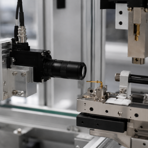
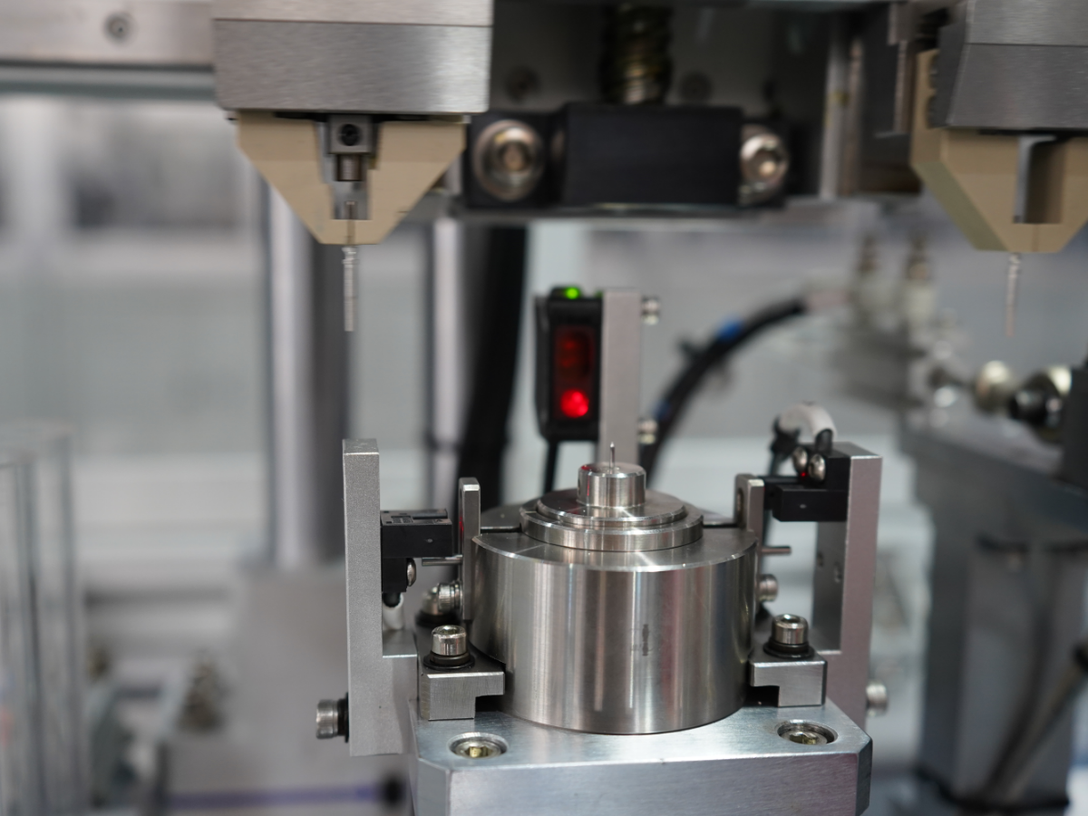
Reflectivity is where naive setups quietly fail. Gold-plated contacts, phosphor-bronze terminals and beryllium-copper springs throw glare that washes out a flat ring light, so genuine pin-inspection rigs lean on telecentric lenses and diffuse dome lighting to read a clean, Z-insensitive shadow of each contact. The spectrum below is how ZEUEE scopes an inspection cell for a given connector family.
Contact Defect Spectrum — by defect family, vision method and tolerance
| Defect family | Example defects | Vision method | Typical sensitivity |
|---|---|---|---|
| Geometry — position | Bent pin, true-position drift | 2D telecentric shadow | from 0.3° / 20 µm |
| Geometry — height | Coplanarity, pin height | 3D laser / structured light | <0.1 mm |
| Presence / count | Missing pin, wrong pole count | Pattern match | 100% per part |
| Surface — finish | Plating void, discoloration | Color + grayscale | shade delta |
| Surface — cleanliness | Dust, oil film, debris | Surface defect AI | sub-mm particle |
| Edge integrity | Burr, chip, crack | Contour + texture | µm-level edge |
| Dimensional | Concentricity, diameter | Calibrated gauging | ±0.02 mm |
| Insertion | Insertion depth, seating | Side-view profile | 0.05 mm step |
| Housing | Shell deformation, flash | Profile comparison | contour fit |
Not sure which modality your defects need?
request a custom defect-coverage estimate →Inside the ZEUEE Inspection Machine, Multi-CCD Vision-Station Blueprint
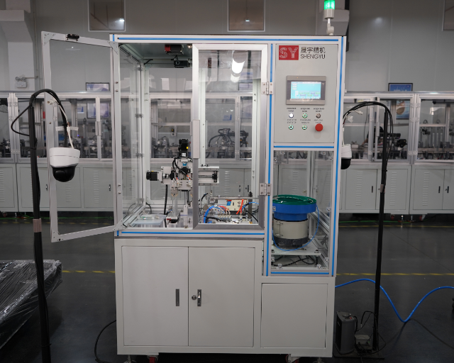
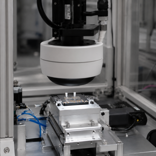
An inspection machine is only as good as how its stations are arranged around the part. Our engineers build connector inspection automation as a sequence of CCD vision stations, each with dedicated lighting, feeding a single accept/reject decision and a data record, the AI vision-inspection architecture is described in USPTO US 12,205,273. The blueprint below is the standard cell layout our engineers configure; station count and camera resolution scale with the connector and the throughput you need.
Multi-CCD Vision-Station Blueprint — standard cell configuration
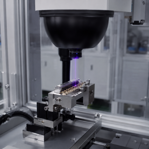
Why ZEUEE separates surface AI (station 5) from the geometry stations is practical: rule-based gauging is precise on dimensions but floods operators with false alarms on cosmetic surface variation, while a trained model handle plating and contamination far better. Splitting the two keep each station doing what it’s good at. Every station ties into your line over PLC and MES, so each part carries a traceability record, which is exactly what a customer audit asks for.
“On plated contacts the first thing we fight is glare, not algorithms. We will not claim a single ring light reads a gold pin, it does not. We size the dome and telecentric optics to the contact finish first, then let the vision do its job. That is the honest version of why two machines quoting the same camera can give very different yields.”
Configuration by connector type — parameter ranges, not Yes/No
Decision Matrix, which configuration fits your connector
| Connector family | Critical check | Vision stations | Coplanarity need | Throughput class |
|---|---|---|---|---|
| Micro-D (MIL-DTL-83513) | Pin bend + coplanarity | 3D + side | <0.05 mm | high-mix, mid-rate |
| Nano-D (MIL-DTL-32139) | Pin presence + position | 3D + top | <0.05 mm | high-mix, low-rate |
| Circular (MIL-DTL-38999) | Insertion depth + shell | Side + profile | 0.1 mm | mid-rate |
| Automotive pin/socket | Burr + plating + count | Surface AI + top | 0.1 mm | high-rate (≈30 parts/s) |
| Rectangular / D-Sub | True position + polarity | Top + 3D | 0.08 mm | mid-rate |
Automated Vision Inspection vs Manual & Sampling QC, Performance Comparison
Plant managers weigh a vision cell against the two things it replaces: a manual inspection bench and a statistical sampling plan. That trade-off isn’t “machine good, people bad” — it’s coverage, consistency and speed against capital cost. Machine-vision inspection has a long engineering record (see, for example, IEEE Xplore document 1612825). Real numbers, not High/Medium/Low, make the case.
Connector inspection methods compared
| Factor | Manual bench | Sampling (AQL) | Automated vision (ZEUEE) |
|---|---|---|---|
| Coverage | 100% but inconsistent | ~1–10% of lot | 100% every part |
| Smallest reliable defect | ~0.3 mm visible | depends on sample | 20 µm / 0.3° |
| Throughput | operator-limited | batch delay | to ≈30 parts/s |
| Coplanarity check | not feasible by eye | gauge subset | <0.1 mm, every part |
| Traceability record | manual log | lot record | per-part data |
| Escape risk | fatigue-driven | between samples | fixed acceptance rule |
Alignment Placeholder
Here’s the honest version that connector buyers rarely hear from a brochure: no vision system catches 100% of every defect forever. Industry deployments report AI surface inspection cuts false positives by 70–90% versus fixed-rule methods while holding detection accuracy above 99%, but 99% isn’t a magic 100%. Rule-based optical inspection in particular floods operators with false calls triggered by lighting shifts and harmless cosmetic variation, and that false-call burden is itself a hidden labor cost. The trade-off worth buying is a shorter defect-escape interval plus an operator-feedback loop that retrains on real misses, not a vendor’s “100% accuracy” promise.
Quality-Escape Economics, The Escape-Cost Payback Gauge
Connector inspection automation isn’t really about labor, it’s about what one escaped lot cost. Automotive suppliers chase a world-class target below 25 DPPM, medical devices below 10 DPPM, against the Six Sigma reference of 3.4 DPPM. A formal quality-management systemISO 9001:2015is what turns that escape math into an auditable process. A spec that sit closer to those numbers makes each escape more worth catching, because the cost lands downstream as line stops, returns and recall exposure, not as a scrapped part.
ROI Outlook, Silver (TCO framework)
Escape-Cost Payback Gauge
Exact payback depends on your part value, escape rate and customer penalty structure, so treat the gauge as a framework, not a fixed figure. Field cost-of-quality data sets the inputs:
| Cost lever | Manual / sampling baseline | With 100% vision |
|---|---|---|
| Escape rate to customer | sampling gaps remain | fixed acceptance rule on every part |
| Supplier recall-cost share | 15–20% exposure | defect-escape interval shortened |
| False-call labor | high on rule-based / manual | cut via trained surface model |
| Inspection labor | per-shift operators | shifted to oversight |
Alignment Placeholder
Hover to reveal
Where to start: the higher your part’s downstream failure cost and the tighter your customer’s DPPM target, the faster a 100% cell pays back. We’ll model it against your numbers rather than quote a generic percentage.
Rather than quote a generic percentage, ZEUEE quantifies this against your actual part value, because an industrial buyer with a sub-25 DPPM customer target sees a very different payback than one shipping commodity connectors. ZEUEE engineers the gauge to your numbers, recall exposure runs 15–20% on escaped lots, and a customer audit can trace every input.
Standards, Compliance & Industries Served
A connector maker evaluating an unfamiliar equipment partner checks one thing before specs: does this supplier actually understand my acceptance standards and can it prove its own quality? ZEUEE scopes inspection acceptance against the frameworks your customers already audit to, MIL-DTL-83513 for Micro-D, MIL-DTL-32139 for Nano-D and MIL-DTL-38999 for circular connectors, with IPC-A-610 and IPC/WHMA-A-620 (current Rev F) as the visual-acceptance references for electronic assemblies and cable products, all underpinned by an ISO 9001:2015 quality system. We map your acceptance class to the vision rule rather than guessing a threshold. For defense and aerospace contacts, where connection security and full traceability are non-negotiable, that mapping is the difference between a clean pass and a latent field fault.
01/10
Building industrial automation since 2005, ZEUEE runs a 20,000 m² production base in Taihe, Jiangxi, with more than 120 staff and over 10,000 cases delivered. That depth is why connector, automotive and electronics makers trust non-standard inspection builds to us rather than an off-the-shelf box.
Long-term customers include AVIC, China Shipbuilding, GAC Group, Corning (USA), Hunter, TE, Sumitomo (Japan), LEGO (Denmark), TCL, SONY and Foxconn — across aerospace electronics, automotive, 3C electronics, precision electrical, medical and new-energy industries.
For an aerospace or automotive industrial buyer, a supplier that cannot map inspection to your acceptance class is a risk, one escape can mean a 15–20% share of a recall. ZEUEE engineers close that gap because a customer audit will check it, and ZEUEE certifies to ISO 9001:2015 with 30+ countries of installed base behind the claim.
Procurement Guide, Line Integration, Lead Time & Support
Buyers tell us the same priority order: quality commitment first, then price, then delivery, then how transparent the process is, the supplier-quality discipline behind that order is formalized in ISO 9001:2015. A connector inspection cell is a non-standard build, so the cost is driven by configuration, not a list price. Those factors shape a quotation; we give you the drivers up front rather than a number that does not fit your part.
What drives the quotation
On integration, ZEUEE delivers the cell with the PLC and data interface matched to your line controls, runs an on-site acceptance against your sample defects, and trains your operators on the reject and feedback workflow. Lead time and warranty are set at quotation against the configured scope, contact us for a lead-time estimate based on your specification.
Engineering & Configuration Tools
Access our suite of analytical tools to quantify your quality escape costs, calculate process capabilities, and specify the exact vision architecture required for your assembly line.
Connector Inspection Machine Questions
What defects can automated connector inspection detect?
Bent and missing pins, coplanarity and pin-height drift, true-position and concentricity errors, burrs, chips, plating voids, surface contamination, insertion-depth shortfalls, polarity and pole-count errors, and shell deformation, using a mix of 2D, 3D and surface-AI vision matched to the defect family.
How does machine vision inspect pin and socket contacts?
Each part is fed and indexed, then imaged at several CCD stations: a top camera for presence and count, a side telecentric view for bend and depth, a 3D sensor for coplanarity, and a high-resolution surface station for burrs and plating. Those stations feed one accept/reject decision and a per-part data record.
What are the 4 types of inspection?
In manufacturing, inspection is usually grouped as incoming (receiving), in-process, final and pre-shipment. A connector inspection machine most often sits at the in-process and final stages, giving 100% coverage where sampling used to leave gaps.
Does automated inspection really reach 100% accuracy?
No, and you should be cautious of any vendor who promises it. Industry deployments report AI surface inspection cutting false positives by 70–90% versus fixed-rule methods while holding detection above 99%, which is excellent but not a literal 100%. The honest goal is a short defect-escape interval and a feedback loop that retrains on real misses, not a perfect number on a slide.
How fast can a connector inspection machine run?
Throughput is configured to the part. High-mix Micro-D and Nano-D cells run slower with more 3D detail, while automotive contact lines are built to keep pace with high-rate production, published automotive cases verify connector geometry at around 30 parts per second to ±0.02 mm.
Why do gold-plated or beryllium-copper contacts need special handling?
They're highly reflective, so a flat ring light produces glare that hides real defects and creates false rejects. Our engineers size telecentric optics and diffuse dome lighting to the contact finish first, this is the part of a quote that separates a reliable cell from one that look the same on paper but underperforms on your parts.
Can the inspection cell integrate with our existing line and MES?
Yes. It ties in over PLC and feeds a per-part traceability record to your MES, so the inspection data support customer audits. Integration scope, standalone versus full inline, is set at quotation.
WHY WE WRITE THIS
About ZEUEE Engineering Insights
ZEUEE shares technical guides based on real automation project experience. Since 2005, we have designed and manufactured non-standard automation equipment for connector assembly, wire harness production, robotic lines, vision inspection, and smart factory upgrades.
Founded in 2005
20,000 m² production base
120+ specialists
150+ R&D patents
ISO9001:2015 certified