Get in touch with Zeyu lntelligent Industrial Company

Inside the MIL-DTL-32139 Standard for Nano-D Connectors

![Nano-D Connector: Inside MIL-DTL-32139 [Guide]](https://zeueeauto.com/wp-content/uploads/2026/08/nano-d-connector-mil-dtl-32139-standard-featured.png)
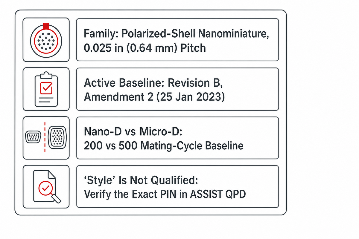
A Nano-D connector is a polarized-shell nanominiature rectangular connector family with 0.025 in (0.64 mm) contact centers. It isn’t fully specified by its family name, pitch, or a catalog claim that it’s “MIL-DTL-32139 style.” A defensible choice links the active military detail specification to the exact slash sheet and part-identifying number, then checks the qualified source, lot evidence, application limits, workmanship rules, and assembly controls. That chain matters because the public records don’t all tell the same story: as reviewed on 13 August 2026, ASSIST identifies MIL-DTL-32139B with Amendment 2 as active, while the limited-access public QPLDOCS search displays MIL-DTL-32139A(1) as its governing specification.
Short answer: use MIL-DTL-32139B with Amendment 2 as the active general-specification baseline, but don’t stop there. Confirm the current ASSIST record, exact slash sheet and complete PIN, the authenticated ASSIST QPD entry, lot-level acceptance evidence, and any customer or mission requirements. Treat QPDSIS and public QPLDOCS as useful but limited public evidence surfaces. Issued in July 2026, the Amendment 3 document is an initial draft and says not to use it before approval.
0.025 incontact centers in one row
1 Acontinuous contact capability
200 cyclesbaseline durability test
1 μsmaximum allowed interruption threshold
ZEUEE, Shenzhen Zeyu Intelligent Industrial Science Technology Co., Ltd. · Updated 13 August 2026 · Public-source analysis; no private Nano-D production or client data is claimed.
What Is a Nano-D Connector?
A Nano-D connector is a polarized-shell, nanominiature rectangular electrical connector used where interconnect envelope and mass are tightly constrained. Using the same public-source boundary established above, that definition narrows the opening evidence chain to the physical family before any configuration is selected. MIL-DTL-32139 covers versions terminated to printed circuit boards or attached to cable assemblies. Within a row, its contacts sit on a 0.025-inch (0.64 mm) centerline. That interface fact identifies the family; it doesn’t identify the full configuration.
Commercial search labels are broader than compliance claims. This guide does not assume that every product marketed as “Nano-D,” “nano miniature,” or a similar term belongs to MIL-DTL-32139. This review covers rectangular, polarized-shell, 0.025-inch-pitch connectors for printed-circuit-board or cable-assembly termination. If a candidate uses another shell geometry, interface, spacing, contact system, or configuration outside the applicable slash sheet, treat the label as vendor-defined and evaluate its own drawing and evidence rather than importing this specification.
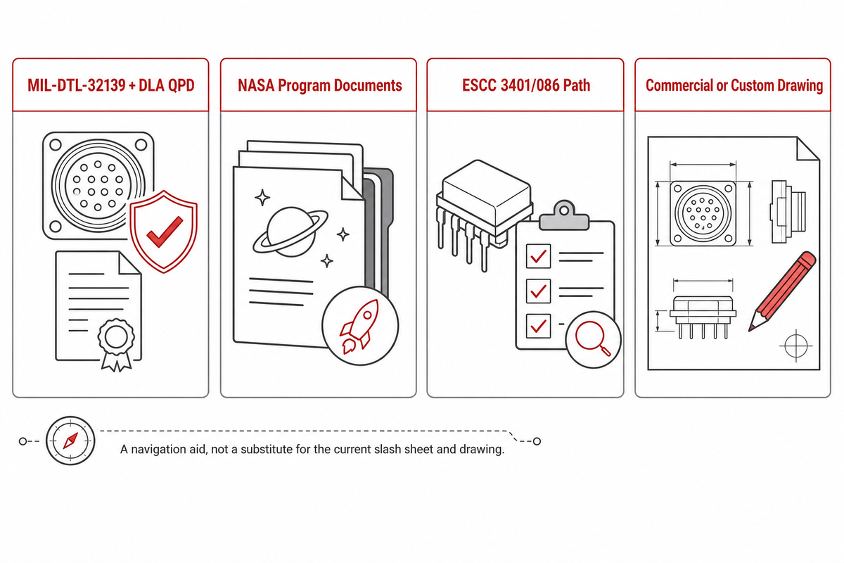
An international space program may also invoke a different evidence path for a similar form factor. ESCIES’s current published-specification list includes ESCC 3401/086 Issue 2 for rectangular nanominiature connectors based on type Nano-D. It is read with the ESCC generic connector specification and does not make an ESCC-qualified item MIL-DTL-32139-qualified—or the reverse. State the governing qualification system on the RFQ before comparing part numbers, test reports, or approved sources.
| Evidence system | Use it when | What it can establish | What it cannot establish by itself |
|---|---|---|---|
| MIL-DTL-32139 plus DLA QPD | The solicitation, contract, drawing, or approved parts baseline invokes the military detail specification | The family requirements and a dated exact-part, exact-source qualification status | Delivery authenticity, every-unit coverage, system fitness, or mission approval |
| NASA program documents | The governing NASA contract or program invokes the applicable parts, workmanship, training, human-systems, or center requirements | The additional application, assembly, personnel, handling, and program evidence named by that invocation | Automatic hardware qualification or applicability outside the stated program and organizational scope |
| ESCC 3401/086 path | An ESCC procurement baseline invokes the detail and generic connector specifications | Conformity and qualification evidence within the ESCC system | Reciprocal MIL-DTL-32139 qualification |
| Commercial or custom drawing | No government or ESCC qualification system is invoked | Vendor-defined interface, materials, tests, and acceptance commitments | Government qualification from a “Nano-D” or “MIL-style” label |
Selecting the complete configuration still requires resolving plug or receptacle, single or dual row, insert arrangement, termination or wire type, mounting and hardware, shell finish, and any applicable space class. Some products are pre-wired. Others use vertical or horizontal printed-circuit-board tails, through-hole contacts, or surface-mount options. A mating pair also needs compatible polarization and hardware, not merely matching contact counts.
Density alone doesn’t settle the architecture. A peer-reviewed description of the RadCube MAGIC instrument used a 51-pin Nano-D interface between each front-end electronics card and the backplane, yet used Micro-D connectors for sensor cable assemblies. One system assigned the two families different jobs. That’s a better engineering lesson than calling the smaller connector universally superior.
Terminology boundary: “Nano-D,” “MIL-DTL-32139 style,” “designed to,” “compliant,” and “qualified” answer different questions. Only the exact record and evidence package can show which statement is supportable for a particular part.
What Does MIL-DTL-32139 Actually Cover?
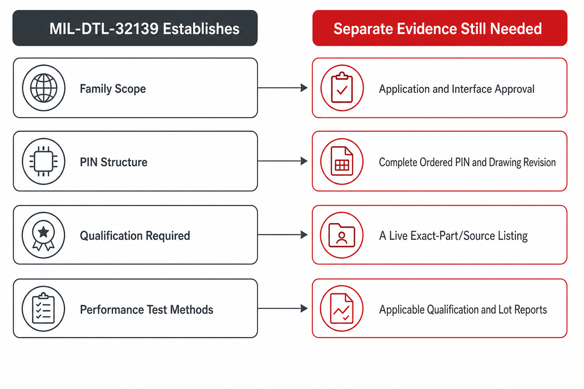
MIL-DTL-32139B with Amendment 2, dated 25 January 2023, is the active general specification reviewed for this guide. That family-level boundary carries forward the distinction between a connector family and a fully specified part. MIL-DTL-32139 establishes requirements, test methods, the quality-conformance structure, the qualification obligation, and the PIN architecture. Geometry and configuration details come from the relevant detail specification sheet. If the general specification and a slash sheet conflict, the slash sheet controls.
Freeze the slash sheet separately from the parent document. DLA’s MIL-DTL-32139 document-family index shows independently dated sheets; for example, /11 through /14 carry Amendment 1 dated 19 March 2025, later than the 2023 parent baseline. A later sheet date does not by itself mean the parent is obsolete. It means the RFQ, drawing review, and change-control record must identify the exact current sheet revision that governs the selected PIN.
Use the normative PDF and slash-sheet drawing for dimensions. As reviewed on 12 August 2026, DLA’s family-index summary renders the 0.025-inch pitch as 0.064 mm, while the current Quick Search record and revision B PDF use 0.64 mm; 0.025 in is 0.635 mm and rounds to 0.64 mm. An older 2004 amendment also carried the 0.064 mm text. This is a page- and document-specific metadata discrepancy, not an error in the current Quick Search record. Reconcile units against the controlled document instead of assuming every official summary field is identical.
| Question | MIL-DTL-32139 can establish | Separate evidence still needed |
|---|---|---|
| Family scope | Nanominiature polarized-shell connectors for PCB or cable assemblies | Application and interface approval |
| PIN structure | Fields that identify slash sheet, insert, termination, hardware, finish and space class | The complete ordered PIN and drawing revision |
| Qualification | Qualification is required before contract award | A live exact-part/source listing |
| Performance tests | Methods, conditions and family requirements | Applicable qualification and lot reports for the delivered item |
| Process control | Statistical process control where practical, with permitted documented alternatives | The supplier’s validated control plan and records |
| Mission acceptance | No automatic space-level assurance; the DLA page marks space-level requirements “No” | Customer, program and mission-specific approval |
Is Amendment 3 Already in Force?
No. DLA Quick Search still lists revision B with Amendment 2 as the active released document and separately shows project 5935-2026-047. DLA labels the 24 July 2026 Amendment 3 file as an initial draft whose cover says it is unapproved, may change, and must not be used before approval. Track the project, but keep the released baseline in acceptance documents until DLA issues an approved change.
This active-change alert also illustrates why a purchase order should cite the document date or revision rather than only listing “latest MIL spec.” “Latest” can shift between quote, first article, and delivery. A date-bound baseline together with a negotiated change-notification clause is reviewable.
Inside the Specification: Interfaces, Contacts, and PCB or Cable Configurations
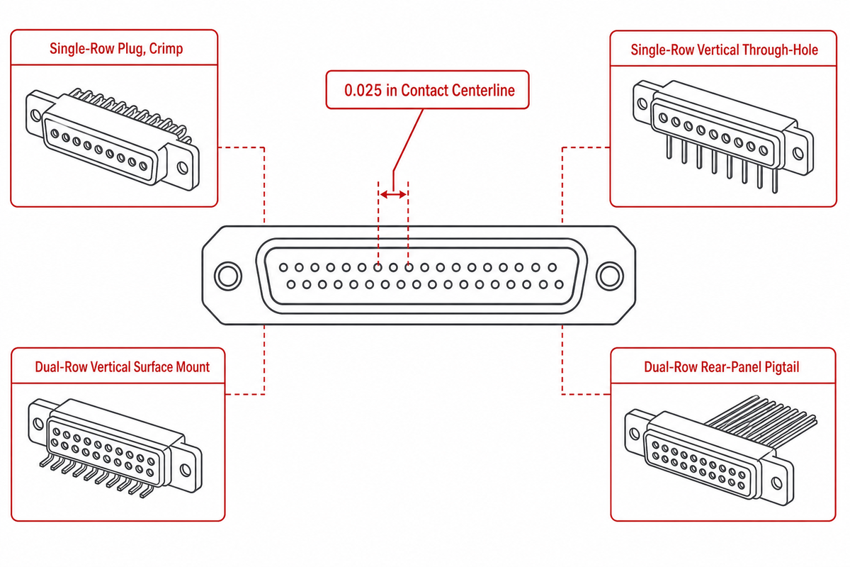
The slash-sheet number is the first configuration branch after the basic specification. It prevents a common error: treating all Nano-D forms as one interchangeable product. Below, a matrix clusters the public document family by interface role. It’s a navigation aid, not a substitute for the current slash sheet and drawing.
| Configuration type | Slash sheet(s) | Contact/interface role | Question to resolve |
|---|---|---|---|
| Single-row plug, crimp | /1 | Pin contacts | Wire type, insert and mating receptacle |
| Single-row receptacle, crimp | /2 | Socket contacts | Wire, hardware and mating plug |
| Dual-row plug, crimp | /3 | Pin contacts | Row arrangement and polarization |
| Dual-row receptacle, crimp | /4 | Socket contacts | Mating orientation and hardware |
| Single-row vertical through-hole | /5 and /6 | Plug and receptacle PCB forms | Board thickness, hole pattern and tail geometry |
| Single-row horizontal through-hole | /7 and /8 | Right-angle PCB forms | Keep-out, tail alignment and solder access |
| Dual-row rear-panel pigtail | /9 and /10 | Plug and receptacle with insulated wire | Panel, gasket, wire and strain-management details |
| Dual-row vertical through-hole | /11 and /12 | Plug and receptacle PCB forms | Tail option, footprint and stand-off |
| Dual-row horizontal through-hole | /13 and /14 | Right-angle plug and receptacle | Coplanarity, bend geometry and solder-joint access |
| Dual-row vertical surface mount | /15 and /16 | Surface-mount plug and receptacle | Pad design, tail area and placement control |
| Dual-row horizontal surface mount | /17 and /18 | Right-angle surface-mount forms | Pad layout, board edge and coplanarity |
| Space-class suffix | Where applicable | Additional PIN field | Whether the exact slash sheet and source support it |
How Do You Read a Nano-D Connector Part Number?
Read the PIN from left to right: the M prefix, basic number 32139, slash-sheet number, insert arrangement, termination or wire type, hardware designator, shell finish, and space-class letter when applicable. For example, two parts can share M32139/ and still differ at every remaining field. Don’t infer an omitted field from a photo or a mating half. Put the complete PIN, drawing revision, and precedence rule on the RFQ so suppliers quote the same configuration.
How Should You Translate Nano-D Catalog Language?
Catalog vocabulary helps buyers find candidates, but it remains source-specific. Omnetics Connector Corp. uses the catalog term Bi-Lobe®, including the phrase dual row Bi-Lobe®. In catalog language, this is a connector technology with 0.635 mm nominal contact spacing, commonly expressed as 0.025 in or rounded to 0.64 mm. These product names are trademarks, not generic requirements of the military specification or evidence that another supplier’s construction is equivalent.
Catalog-data hygiene: if an exported field contains “black anodizedaluminum shell,” normalize it to “black-anodized aluminum shell” before comparing finishes. Here, the merged token is a source-data artifact, not a material designation.
An Omnetics connector page may describe a dual row Bi-Lobe® form, a gold plated flex pin contact, or a plated flex pin contact system. Axon’s, Glenair’s, and other manufacturers’ constructions likewise need their own drawings and qualified-part records.
Search results also group miniature connectors under terms such as D-sub, D-subminiature, Nano connectors, PCB rectangular connectors, panel mount, straight tails, SMT, latching Nano-D connectors, positive lock, screw hardware, and backshells. Nano-D connectors are available in multiple mounting and termination routes, but a term such as “panel mount” doesn’t resolve gender, row count, insert, hardware, or qualification. One manufacturer’s product page may show 1.27 mm PCB-tail spacing even though the mating contact spacing remains 0.025 in (0.64 mm) between centers in the same row; keep those dimensions in their proper drawings.
Materials and applications need the same restraint. Nickel, passivated surfaces, shell plating, and a pin contact system are configuration-specific. Phrases such as “half the size,” “highly reliable,” “rugged,” or “extremely rugged” aren’t acceptance criteria. For satellite, geophysical, high shock, or high-vibration service, translate each adjective into a measured load and test condition. Miniaturization can deliver low mass in applications where size and weight matter, but an attempt to miniaturize the interface still requires handling, cycling, thermal, and sourcing evidence. A robot can repeat an assembly motion; it can’t validate the requirement by repetition alone.
2026 flat-tail change watch
A DLA Engineering Practice Study dated 4 March 2026 recommends a minimum flat-tail cross-sectional area of 5 × 10⁻⁵ in² for slash sheets 5–8 and 11–18. That report discusses solder-flow and electrical-performance concerns. It’s a recommendation, not proof that the active slash sheets already contain that limit. Record it as a drawing-watch item and verify the current sheet before release.
Which Performance and Environmental Evidence Matters?
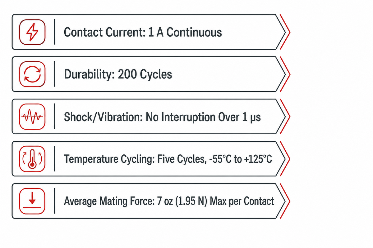
A useful rating has four parts: the characteristic, its limit, the test condition, and the record that proves the exact item was evaluated. Removing the condition can turn a valid test number into a dangerous operating assumption. Voltage provides the clearest example.
MIL-DTL-32139 gives 250 V at sea level and 100 V at 70,000 ft before humidity. For the post-humidity sequence, the 100 V sea-level condition applies specifically to Class M, Types I and II; it is not a blanket value for every configuration. The table labels these as test voltages, not working voltages. Although each contact has a 1 A continuous-current capability, an application still needs conductor, ambient, bundling, temperature rise, creepage, insulation, and system-derating review.
That 70,000-ft proof condition is not a complete pressure-trajectory analysis. Active NASA-HDBK-4007A, dated 3 February 2026, treats Paschen and corona discharge as distinct high-voltage spacecraft hazards and provides design guidance for mitigating them. Apply that handbook only where its high-voltage space-system scope is relevant. A Nano-D application that crosses pressure regimes still needs its own voltage, geometry, insulation, contamination, pressure, time, and test-margin analysis; neither the 100 V altitude proof nor a sea-level test supplies a general working-voltage rating.
Calling a connector “commonly used in digital applications” is not a data-rate qualification. MIL-DTL-32139 includes low-signal contact-resistance tests but does not assign an application channel’s impedance discontinuity, insertion loss, return loss, crosstalk, skew, eye opening, bit-error rate, or simultaneous-switching margin. High-speed use therefore needs a mated-channel model and measurement across the exact connector, launch, board stack-up, cable, return path, pin assignment, and operating conditions.
Signal integrity and electromagnetic compatibility are related but separate closures. A passing channel model does not establish shielding or emissions performance. Shell and finish conductivity, backshell bonding, shield termination, cable construction, unused-contact treatment, enclosure seams, and chassis or signal return paths need a system-level electromagnetic-compatibility plan and test evidence; MIL-DTL-32139 qualification alone does not supply it. As a center-specific example, active MSFC-SPEC-521D says enclosure-connector design must be developed with interconnecting wiring/cabling and compatible bonding provisions. That Marshall specification is not universally applicable, but the dependency it exposes must be closed by the governing system requirements.
Relevant radio-frequency or high-electric-field applications can add a low-pressure breakdown check. NASA Lesson Learned 770 describes RF breakdown and multipaction risks for RF hardware, cables, and connectors at critical pressure or in vacuum and calls for demonstrated margin above expected operating RF levels. This is not a general Nano-D qualification requirement, and it does not mean every digital Nano-D link needs an RF vacuum test. It is a trigger to evaluate voltage, frequency, reflected power, gap geometry, pressure trajectory, and test margin when the application can create that mechanism.
| Characteristic | Reviewed baseline | Condition that must travel with it | Evidence to request |
|---|---|---|---|
| Contact current | 1 A continuous | Per-contact capability; application derating is separate | Qualification basis and design-load review |
| Contact wipe | 0.015 in minimum | Mated contact system | Drawing and inspection/test record |
| Average mating force | 7 oz (1.95 N) max per contact | Average across the connector | Test result for the applicable configuration |
| Shock/vibration continuity | No interruption over 1 μs | Specified shock and vibration tests | Qualified test report and monitoring setup |
| Durability | 200 cycles | 100 ± 50 cycles/hour test rate | Durability test and post-test results |
| Temperature cycling | Five cycles, -55 °C to +125 °C | Specified dwell and sequence | Environmental qualification record |
| Salt spray context | 48 hours in intended-use description | Finish and applicable test configuration | Finish-specific qualification evidence |
| Retention reporting | 24-month Group A and 36-month Group B intervals | QPL-retention reporting, not lot shelf life | Current qualification status and supplier records |
Magnetic permeability is another explicit qualification line, not a property to infer from a stainless-steel material name. Section 3.3.4 requires connector and associated-hardware materials to let a connector pair meet a permeability value below 2μ, and section 4.7.3 calls for measurement under ASTM A342/A342M on wired or unwired, non-energized connectors. Request the applicable qualification result when magnetic behavior can affect the system; this test does not replace an integrated magnetic-compatibility analysis.
For production lots, Group A is the lot-conformance layer. Completed assemblies receive 100% insulation-resistance and dielectric-withstanding checks, while other inspections and tests use the defined sampling structure. Calling a connector “100% tested” is therefore incomplete unless the statement names the characteristic. It does not mean every mechanical, dimensional, environmental, and material requirement was checked on every delivered connector.
Ask for an attribute-by-attribute coverage map rather than a generic certificate or a one-line “lot tested” statement. For each required characteristic, the map should name the governing method and condition, show whether the evidence is unit-level, lot-sampled, or periodic, state the sample size or frequency, link the result to the unit or lot identifier, and disclose exceptions, nonconformances, and approving dispositions. This prevents the two completed-assembly electrical screens from being silently generalized to characteristics covered by sampling or qualification-retention tests.
Static resistance and dynamic continuity are different evidence, too. MIL-DTL-32139 measures contact resistance and low-signal contact resistance under their stated circuits, but its shock and vibration procedures use a monitoring circuit to detect interruptions longer than 1 microsecond. A satisfactory post-test or average resistance value can miss a short time-domain excursion that matters to a particular logic, clock, power, or safety circuit. Preserve both records where the failure consequence warrants it, then set the application-specific interruption threshold and monitoring bandwidth instead of treating one resistance number as complete system proof.
Service loads may exceed the qualification envelope or use a different combination of stressors. MIL-DTL-32139 describes intended operation from 10 to 2,000 Hz at up to 20 g and a 100 g shock context, but a buyer should compare the actual spectrum, mounting, cable mass, thermal profile, number of mates, contamination, and failure consequence to the evidence submitted. Passing one family-level qualification does not complete that analysis.
An adjacent Sandia nano-miniature connector fretting study reinforces why a qualification cycle count is not a service-life prediction. In its unlubricated laboratory tests, individual connectors first exceeded the study’s 0.5 Ω failure criterion between 2,341 and 45,238 fretting cycles. This 1999 lubricant study used its own test conditions and does not establish MIL-DTL-32139 qualification, operating life, or a universal maintenance interval. It is a reason to validate small-motion fretting, finish, and lubricant behavior against the actual vibration and handling profile.
Test setup details provide useful audit checkpoints. Sea-level dielectric-withstanding testing uses 250 V at 60 Hz, while the altitude test uses 100 V at 60 Hz. For insulation resistance, the separate procedure applies 100 V dc ±5%. During vibration testing, the attached wire bundles are clamped at least 102 mm from the connector rear, with a ±13 mm tolerance. These are controlled test conditions, not values to copy into an application requirement without an engineering review.
Space-use finish selection has its own hazard boundary. MIL-DTL-32139 states that aluminum shells for space applications use electroless nickel and says cadmium is normally prohibited on space electrical, electronic, and electromechanical parts unless specifically approved. Its application note warns that cadmium can sublimate in hard vacuum, especially above 75°C, and conductive deposits can cause shorts or interfere with optics. Qualification does not replace contamination and finish-compatibility review.
Pure tin creates a separate receipt-verification problem. MIL-DTL-32139 prohibits pure tin and limits tin content in connector materials to 97%, with an alloy selected to inhibit whisker growth. NASA’s pure-tin prohibition guidance warns that procurement errors can still deliver pure-tin-plated components and that visual inspection generally cannot distinguish them reliably from tin-lead or nickel finishes. That NASA page is program guidance, not a universal inspection mandate, but it supports a practical risk decision: where finish composition is critical, define certificates, lot traceability, and an appropriate analytical verification method instead of relying on appearance alone.
For PINs using an applicable space-class field, MIL-DTL-32139 sets a thermal-vacuum outgassing test boundary: maximum total mass loss of 1.0% and maximum volatile condensable material of 0.1%, with nonmetallic materials and lubricants evaluated under ASTM E595. “Space class” here is a configuration and test category, not proof of space-level reliability—the DLA qualification page explicitly marks that broader field No. These are the specification’s test acceptance figures, not universal spacecraft contamination limits; a program may evaluate additional metrics or impose tighter controls around optical, thermal, or vacuum-sensitive hardware. Complete component and mission contamination budgets still require review.
Radiation assurance remains a separate application axis. NASA’s Parts Selection List use policy says a device-technology listing does not imply or guarantee radiation hardness assurance unless the table specifically says so, and it directs radiation-sensitive applications to program experts for assessment of effects such as total ionizing dose and single-event effects. That same boundary applies here: a space-class PIN, QPD status, outgassing result, or connector-family listing does not establish radiation tolerance for the connector assembly, its insulation, or the circuit it serves.
Outgassing does not prove finished-connector cleanliness. Current JPL QC118, used here only as a project-clause example, separately calls out excessive adhesive or lubricant, molding flash, insert chip-outs, and foreign-object debris that can interfere with a connector or break loose during mating, thermal exposure, or vibration. An ASTM E595 material result and a clean visual/inspection record answer different questions. Buyers should define the cleanliness clause, inspection method, magnification or measurement limits, packaging, and nonconformance disposition required by their own program.
Storage can create a different materials interaction. Section 6.1.3 of MIL-DTL-32139 directly warns that corrosion has occurred on connectors prewired with SAE AS22759/33, /51, or /52 wire and stored in a sealed environment. An adjacent NASA MIL-PRF-83513 application note describes one fluoropolymer, moisture, and metal-finish mechanism and recommends inspection and ventilated, humidity-controlled storage for its Micro-D context. Use the Nano-D warning as the applicable trigger, then verify construction, packaging duration, humidity, incoming inspection, and project controls. Do not treat the neighboring NASA note as a universal chemistry diagnosis for every Nano-D assembly.
Derating is another separate decision. NASA GSFC’s EEE-INST-002 page describes selection, screening, qualification, and derating as baseline criteria specifically for NASA Goddard Space Flight Center space-flight projects. It is neither a NASA-wide connector requirement nor a universal Nano-D rule. Within that explicit scope, it illustrates why current, temperature rise, conductor size, bundle conditions, and project stress limits must be closed after the connector’s qualification status is known.
Nano-D vs Micro-D: When Smaller Is Not Automatically Better
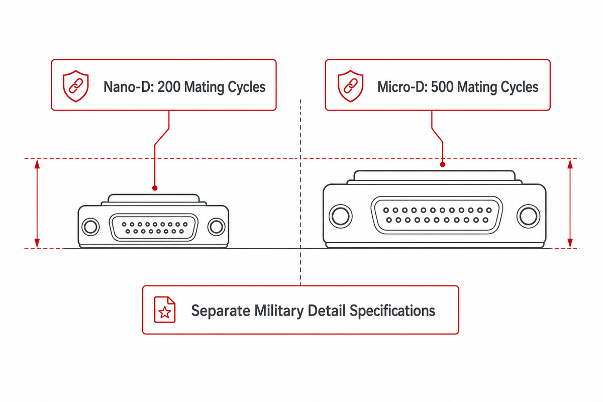
Nano-D and Micro-D are separate connector families governed by different military detail specifications, not interchangeable dimensional options. DLA Quick Search lists MIL-DTL-83513 as an active microminiature-connector specification with its own document and qualification record. Nano-D can reduce interface area and mass. Micro-D can be the better fit when a program values a different contact arrangement, termination ecosystem, handling margin, availability path, or cycling requirement. Start the comparison with governing specification and system constraints, not a size ranking.
Official durability baselines expose the trap. MIL-DTL-32139 specifies 200 Nano-D mating cycles. MIL-DTL-83513H with Amendment 2 specifies 500 Micro-D mating cycles. Those figures describe their respective standard tests; they do not predict the life of every supplier variant. They do show why “smaller” cannot be translated into “more durable” without evidence.
For NASA spaceflight work, the MIL-PRF-83513 application notes add part-level distinctions that can outweigh size: Level 2 preference, additional Level 1 screening, wire-insulation radiation tolerance, conductor strength under severe thermal cycling, and a warning that some 26 AWG lead constructions may conflict with the cited workmanship preference. These are NASA program notes for Micro-D, not MIL-DTL-32139 requirements and not a universal reason to select one family. They show why the comparison must use the exact prewired construction, wire, screening level, workmanship rule, environment, and program approval.
| Decision signal | Nano-D may fit when | Micro-D may fit when | Evidence before selection |
|---|---|---|---|
| Envelope and mass | The 0.025 in interface is needed to protect board or payload space | The larger interface is acceptable | Mated CAD, keep-out and cable-assembly model |
| Repeated mating | The verified duty remains within the applicable configuration’s evidence | The 500-cycle baseline better matches service access | Actual mate count, maintenance plan and test report |
| Handling | Fixtures, access and mating controls protect the smaller interface | Field handling or technician access favors more physical margin | Service simulation and damage criteria |
| Qualified sourcing | Exact Nano-D PIN/source and lead time are verified | Micro-D has the stronger approved-source path for the program | Current QPD, approved supplier list and lifecycle plan |
| Architecture | A dense board or backplane boundary benefits from the smaller interface | A sensor-cable or service boundary benefits from the Micro-D ecosystem | Interface control document and FMEA |
Connector footprint is not the whole service envelope. The live NASA catalog checked on 13 August 2026 lists NASA-STD-3001 Volume 2 Revision F, dated 14 July 2026, as active; for crew-accessed human-spaceflight systems, it includes connector access and spacing requirements tied to expected clothing and tool use. Its Section 12.1 ground-processing rules are narrower: they apply to flight systems handled at integration, launch, landing, recovery, or deservicing sites; are optional at manufacturing and development sites; and do not apply when one vendor owns design, assembly, and maintenance. These are conditional human-systems requirements, not universal Nano-D spacing values. Model the installed finger, glove, tool, strain-relief, and inspection work envelope for the actual program.
What Are Micro-D Connectors Used For?
Micro-D connectors serve compact board, cable, and equipment interconnects where a D-shaped polarized interface and multiple contacts suit the application. They are common in aerospace, defense, instrumentation, and other high-reliability systems, but the family name alone does not establish qualification.
It also does not establish a specific environmental rating. For the document boundary, see ZEUEE’s MIL-DTL-83513 Micro-D connector guide.
Which Nano-D Specification Mistakes Cause Rework?
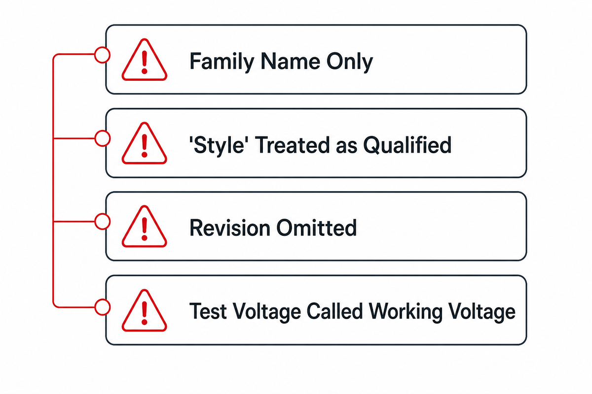
Most preventable failures begin before assembly. An ambiguous RFQ becomes an ambiguous quote; an ambiguous quote becomes a configuration mismatch, late evidence dispute, or redesign. MIL-DTL-32139’s acquisition-description rules show why the complete detail-specification reference and PIN matter. Below, the register separates each mistake from the evidence that closes it. That is a sourcing-control problem first.
| Failure mode | What goes wrong | Control before order | Acceptance evidence |
|---|---|---|---|
| Family name only | Plug/receptacle, row, termination or finish remains open | Complete slash sheet and PIN | Configuration drawing |
| “Style” treated as qualified | Commercial resemblance substitutes for status | Check exact part and source live | Dated QPD/QPDSIS record |
| Revision omitted | Quote, test and receipt use different baselines | Name revision/date and change rule | Controlled contract baseline |
| Mating half assumed | Gender, polarization or hardware does not match | Specify both mating PINs | Fit-check and interface record |
| Test voltage called working voltage | System insulation decision uses the wrong number | Label test condition and design voltage separately | Electrical design review |
| “100% tested” left undefined | Buyer assumes every requirement was screened | Name each 100% and sampled characteristic | Inspection/test report by characteristic |
| QPL called mission approval | Program-specific assurance is skipped | Add customer and mission parts review | Approved parts or deviation record |
| Workmanship scope missing | Qualified product is assembled under undefined rules | Name applicable workmanship standard | Operator/process qualification and inspection |
| Machine capability assumed | Vision or force monitoring is never validated on the part | Run a part-specific measurement study | GR&R, challenge set and release limits |
Do
- Name the active baseline and exact slash sheet.
- Verify the ordered PIN against a live qualified-source record.
- Separate qualification, lot conformance, workmanship and mission approval.
- Define which evidence travels with each lot.
Don’t
- Convert “style” or “compatible” into qualification.
- Use dielectric test voltage as an operating rating.
- Assume a manufacturer is qualified for every catalog variant.
- Treat a generic automation concept as validated inspection.
How to Choose a Configuration with the 6-Gate 32139 Evidence Trail
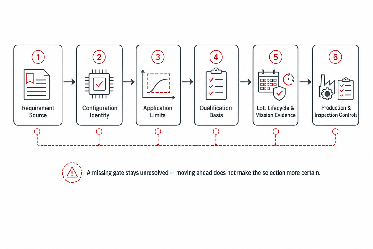
The 32139 Evidence Trail is a stop/go sequence. That generic automation mistake and the other rework risks above become unresolved earlier gates in the ordered evidence path. Each gate answers a different question, and a missing gate stays unresolved. Moving ahead without closing an earlier gate does not make the selection more certain; it merely hides the gap under more documents.
Six gates means six grouped decision checkpoints, not six documents and not an exhaustive compliance taxonomy. Only the six bold labels in the ordered list are gates; the fields after each colon are evidence inputs inside that gate. Gate one groups the parent specification, applicable slash sheet, purchase drawing, and precedence rule; later gates group identity, application, qualification, lot/lifecycle/program evidence, and production controls. Workmanship, supply continuity, integration operations, jurisdictional compliance, and mission approval remain subordinate evidence lines under the applicable gate or separate governing program. This evidence trail organizes a stop/go decision; it does not claim that every evidence line is another gate or erase those distinctions.
- Requirement source: identify the active general specification, applicable slash sheet, purchase drawing and precedence rule.
- Configuration identity: freeze the complete PIN, mating half, insert, termination, hardware, finish and space-class field.
- Application limits: document current, voltage, environment, vibration spectrum, shock, mate count, mounting and failure consequence.
- Qualification basis: verify the exact part/source against current DLA records and reconcile any metadata conflict.
- Lot, lifecycle, and mission evidence: define acquisition, traceability, acceptance tests, sampling, handling, packaging, storage, application controls, customer approval, and deviations where the governing program requires them.
- Production and inspection controls: link every critical characteristic to a validated control, stop limit, record and change trigger.
| If this is missing | Do not do this | Next evidence action |
|---|---|---|
| Document date | Accept “latest revision” as a stable baseline | Capture the current ASSIST record and change rule |
| Complete PIN | Recommend a catalog family | Resolve every PIN field and mating half |
| Load spectrum | Claim qualification equals service life | Build the environmental and duty profile |
| Exact QPD entry | Infer qualification from a company name | Search the ordered government designation/source |
| Lot report | Assume the qualification report covers delivery | Define shipment-level certificate and test data |
| Control validation | Buy a machine from a feature list | Run part trials and measurement-system validation |
How Should Buyers Read QPL and Qualification Evidence?
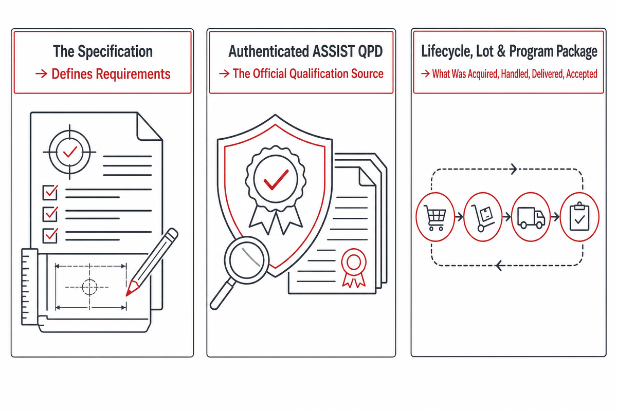
Qualification answers whether a product/source has demonstrated the defined qualification requirements. Within the evidence trail, it is the fourth-gate question, while production and inspection controls remain a later, separate closure. It does not replace the exact configuration check, production-lot conformance, customer approval, or the application’s parts-assurance process. Read the evidence in layers.
Use the authenticated Qualified Products Database (QPD) through ASSIST for the authoritative part/source decision. Defense Standardization Program’s qualification FAQ calls QPD the official source for all DoD qualification data and warns that QPL/QML data available through public QPLDOCS are limited. DLA’s qualification-information page identifies current QPD/QPDSIS information and places the 2006 QPL-32139-1 and QPL-32139-2 documents in its historical section. Treat “QPL” as legacy or generic qualification vocabulary here, not as the name of the current record.
At the time of this review, the public QPLDOCS part-search page showed 12,234 government part records and a last-update date of 30 May 2026. It also displayed MIL-DTL-32139A(1) as the governing specification, even though ASSIST unambiguously lists revision B with Amendment 2 as the active document. So the current specification baseline is not in doubt; the narrower uncertainty is how the public interface’s legacy revision metadata relates to qualification coverage for a particular part. That limited display is not proof that a product lost qualification, and a part record alone cannot prove requalification or retention against every current-revision requirement. Preserve the dated capture, then ask the Qualifying Activity to reconcile the legacy field and exact-part coverage when acceptance depends on it.
A visible record can also carry an “Unresolved Issues” flag at the Qualification Data Set level. DLA’s help page says the flag warns buyers of a potential problem without naming the affected product or manufacturer, to avoid undue acquisition bias. Do not infer which item is affected. Contact the Qualifying Activity for the specific issue before making an acceptance decision; an otherwise exact-looking part/source match does not resolve a deliberately nontransparent flag.
DLA’s help taxonomy also includes a Critical Safety Item field. When that field applies, the Qualifying Activity cannot add or remove a source for the affected aviation-related part without Design Control Authority approval. This is a separate source-change authority condition, not another name for qualification, authenticity, or mission approval. Capture the flag, approving authority, and approval record before treating an alternate qualified source as interchangeable.
Dated 29 May 2026, the five-page QPDSIS lists exact part families and qualified source locations from AirBorn, Axon, Cristek, Dynomax, Glenair, Microway, Omnetics, TE Connectivity, Ulti-Mate Connector, LLC, and Winchester Interconnect Micro LLC. That is not permission to label every product from any listed company qualified. Search the exact government designation and confirm the qualified source in authenticated QPD. That DLA qualification page marks “Specification contains quality assurance program” and “Specification contains space level reliability requirements” as No; QPD status therefore cannot stand in for either program control.
Qualified does not mean multi-source. DLA maintains a MIL-DTL-32139 single-source solicitation list at the government-PIN level while it seeks possible additional sources. For the exact ordered PIN, record the currently approved sources, source-location limits, lead time, obsolescence exposure, and the qualification path for an alternate. A family with several listed manufacturers can still leave one required configuration concentrated in a single supply path.
Qualification is also time-dependent. MIL-DTL-32139 requires 24-month Group A summaries and 36-month Group B requalification reports unless the Qualifying Activity specifies otherwise. Its report certifies that processes, materials, design, construction, and manufacturing locations remain as qualified unless changes were authorized. Inspection failures require immediate notification. An unresolved nonconformance without an accepted corrective action can lead to removal of the affected product from the QPL, and a report submitted more than 30 days after the reporting period can separately lead to loss of qualification. An authenticated, dated QPD lookup should therefore be paired with the exact-part retention status and relevant current reports.
That periodic evidence is not necessarily synchronized with a shipment. Section 4.5 allows delivery not to be delayed while periodic Group B results are pending unless an inspection shows noncompliance; a Group B failure then stops acceptance and shipment until acceptable corrective action and successful reinspection. Consequently, the two 100% completed-assembly electrical tests, sampled Group A lot evidence, periodic Group B evidence, and application validation answer different questions. Completing all six ladder gates does not prove that every delivered unit was tested for every characteristic or that the connector is suitable for the end use.
Do not read those two database flags as “the specification has no manufacturing controls.” Section 3.2.1.1 of MIL-DTL-32139 separately requires the contractor to implement and use statistical process control techniques when possible and maintain that program under SAE EIA-557 or MIL-STD-790. Portal metadata, product qualification, contractor process control, and mission assurance are four different layers.
Plant and process continuity are part of qualification identity. Active SD-6, dated 1 February 2026, requires qualification applications to identify each manufacturing plant and says the Qualifying Activity must be notified of changes in design, material, manufacturing processes including quality control, or plant location. Its retention certification asks whether the listed product remains available from the listed plant under the originally qualified conditions. This general program guidance reinforces, but does not replace, the MIL-DTL-32139-specific retention reports and change approvals.
Space programs add another boundary. NASA’s Parts Selection List guidance says participation in QPL, QML, or ISO 9000 does not automatically qualify a product for the NASA list, and the project or parts organization must assess fitness independently. NASA-STD-8739.10 separately covers selection, acquisition, traceability, testing, handling, packaging, storage, and application of electrical, electronic, and electromechanical parts for NASA spaceflight hardware and critical ground support equipment; its scope says it does not apply to aeronautics systems unless a governing document specifically invokes it. These NASA rules are not universal procurement law, but they show why QPD listing, complete lifecycle assurance, and mission approval must not be merged.
Three records, three questions
The specification defines requirements. Authenticated ASSIST QPD is the official qualification source; QPDSIS and QPLDOCS are limited public snapshots. Together, the lifecycle, lot, and program package shows what was acquired, handled, delivered, and accepted. Ask for all three evidence layers when all three decisions matter.
Integration and test can add a handling-control layer after an acceptable assembly is delivered. Active GSFC-STD-8013, dated 18 December 2025, covers training, authorization records, tool handling, and procedures for mating and demating flight electrical connectors at Goddard. It is supplemental, not a standalone cable-assembly fabrication-and-test quality document, not NASA-wide mandatory, and does not govern every Nano-D use. Its own hierarchy says approved engineering procedures or instructions take precedence over it, while it takes precedence over documents referenced in NASA-STD-8739.6 if those documents conflict. It shows why an invoked program may still need to define who may mate or demate, what inspection and protective handling apply, how each operation is logged, and when damage or contamination stops integration.
Repeated test access also consumes connector life even when each operation follows procedure. In its NASA critical-work scope, NASA-STD-8739.4A with Change 4 says connectors have finite life and describes connector savers for hardware exposed to frequent mating during test and checkout. Saver use transfers wear to non-flight jumper-cable connectors, but it is not an uncontrolled sacrificial accessory: the standard says savers must be clearly marked, meet the same requirements as a flight connector, and follow engineering instructions when mating with flight hardware. This does not create a universal Nano-D mandate or replace the 200-cycle MIL-DTL-32139 durability baseline. It supplies a program-control question: count every mate/demate, define the allowed duty and inspection points, and decide whether a qualified, traceable saver is needed before qualification-test cycles are mistaken for an unlimited integration budget.
Energization state is a separate control variable from cycle count. NASA contractor report CR-2002-211839 discusses deadfacing for powered connector mating or demating on space vehicles in application-specific shock, explosive-vapor, electromagnetic-interference, and radio-frequency environments. It is design guidance, not a MIL-DTL-32139 requirement and not proof that every Nano-D interface must use the same deadfacing architecture. For an actual system, identify all external and stored-energy sources, define the approved powered/unpowered state and verification step, and assess arc, short, personnel, explosive-atmosphere, electromagnetic, and RF consequences before the mating procedure is released.
From MIL-DTL-32139 Requirements to Connector Assembly Controls
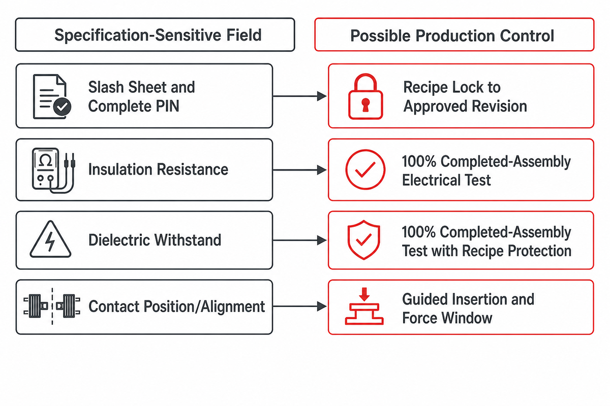
MIL-DTL-32139 defines connector requirements and verification. It doesn’t prescribe one connector assembly machine. Below, the Requirement-to-Control Handoff is an engineering synthesis: each first column comes from a source-bound requirement or configuration field; each proposed control still needs validation for the actual product, equipment, measurement system, and acceptance plan.
Workmanship and lifecycle assurance can sit in different document layers. NASA’s current catalog says NASA-STD-8739.4A with Change 4 applies to critical work as defined by NPD 8730.5; a NASA relationship or an ordinary cable build does not establish that applicability by itself. Governing contracts and program quality plans must identify and tailor the workmanship route. NASA-STD-8739.10 covers the broader parts-assurance lifecycle. Neither automatically governs every Nano-D build.
Where NASA-STD-8739.4 is invoked for critical cable-assembly work, it is an independent design-and-workmanship layer rather than a downstream crimp instruction. Its design practices cover current and voltage derating, voltage drop, spare-contact and arc-tracking considerations, connector identification, and prevention of mismating through layout, size, polarization, keying, marking, or confidence-loop methods. It also requires wire insulation, contacts, sleeving, and related materials to suit the application environment. Those obligations belong in the cable/interface control package; MIL-DTL-32139 product qualification does not close them.
Lot and completed-assembly records still do not cover installation-induced damage. NASA Lessons Learned 30101 reports that much of the cited cable-assembly damage occurred during installation or maintenance and treats post-installation electrical testing, including applicable insulation-resistance and dielectric-withstanding-voltage checks, as a separate control. Plan the test so avionics are isolated and access or manipulation does not create new damage. This is program-specific cable-integration evidence, not a universal MIL-DTL-32139 lot test.
NASA-STD-8739.4 is not the exclusive NASA workmanship route. NASA’s Workmanship Standards Program says IPC/WHMA-A-620-Space is an equivalent standard and the preferred document for new NASA programs and projects; NASA-STD-8739.4 remains available rather than being silently replaced. Each contract and approved manufacturing plan must identify the selected route, applicable exceptions, and inspection basis instead of mixing clauses from both as though they were one document.
Personnel evidence is separate from hardware evidence. Active, NASA-mandatory NASA-STD-8739.6B supplies manufacturing, quality, and training requirements for NASA mission hardware. NASA’s role guidance distinguishes operator, inspector, and instructor roles and requires role-appropriate hands-on exercises, practical examinations, and grading; a generic course certificate or a passing connector test does not prove authorization and proficiency for every role. Ask for the governing workmanship standard, approved training route, role/credential matrix, current qualification dates, practical-exam evidence, and authorization records alongside the assembly traveler.
Electrostatic-discharge control has an additional local boundary. NASA’s Workmanship Standards Program says each location or plant working under the applicable ANSI/ESD and NASA site-control path maintains a site-specific ESD control plan and trains personnel to that plan; visiting operators and inspectors must complete the local plan training before working with ESD-sensitive items. This does not make every Nano-D connector ESD-sensitive or impose a NASA plan on non-NASA production. Where the invoked hardware classification and work environment require it, request the applicable plan and revision, protected-work-area definition, local training and authorization records, handling and packaging controls, and audit evidence instead of accepting a generic corporate ESD certificate.
| Specification-sensitive field | Possible production control | Verification method | Record to retain |
|---|---|---|---|
| Slash sheet and complete PIN | Recipe lock to approved revision | Barcode/OCR match to traveler | Configuration genealogy |
| Plug/receptacle and polarization | Keyed fixture and part-presence logic | Vision pose/class check | Image and decision result |
| Insert arrangement | Cavity map and sequence interlock | Count/position comparison | Insertion map |
| Pin/socket contact identity | Component identification before load | Vision or gauged feature check | Lot and feeder traceability |
| Contact position/alignment | Guided insertion and force window | Position plus force-displacement trace | Cycle curve and limits |
| 0.015 in minimum contact wipe | Assembly-stack and travel control | Section, gauge or qualified functional check | Setup approval and sample result |
| Pigtail wire type/gauge | Wire-ID and cut/strip recipe | Gauge, length and conductor inspection | Wire lot and preparation data |
| Crimp tensile requirement | Tool condition and crimp-height window | Scheduled axial pull test | Force result and failure location |
| PCB tail geometry | Fixture datum and coplanarity control | Optical/laser dimensional check | Measurement file |
| Flat-tail change watch | Revision-specific tail recipe | Cross-section or width/thickness measurement | Drawing revision and dimensional result |
| Hardware and finish | Part-family segregation and presence check | Visual/material certificate review | Component lot genealogy |
| Insulation resistance | 100% completed-assembly electrical test | Programmed insulation test | Unit-level result |
| Dielectric withstand | 100% completed-assembly test with recipe protection | Voltage/time/leakage monitoring | Unit-level trace |
| Lot sampling and QPL retention | Lot release workflow and due-date control | Record completeness review | Lot report, exceptions and retention status |
US 12,051,251 B2, a third-party patent assigned to Harting Electric Stiftung & Co. KG and unrelated to ZEUEE, describes image-based connector component identification, assembly monitoring, and automatic quality-assurance concepts. That’s useful public evidence that connector features can be recognized and compared during assembly. It doesn’t prove a Nano-D inspection algorithm, detection rate, measurement uncertainty, or ZEUEE installation. Those must come from a challenge set using real good parts, known defects, acceptable variation, lighting changes, fixture tolerances, and an agreed false-accept limit. ZEUEE’s connector inspection automation page provides a commercial starting point for discussing those measurement and rejection requirements.
For buyers exploring automation, ZEUEE’s connector assembly machines page is the commercial bridge. If twist-pin contact production is in scope, the Nano twist-pin machine guide covers that process path; this article remains the product-identity, qualification, and evidence-control layer. Send the controlled drawing, variants, required measurements, defect set, cycle demand, retention format, and acceptance owner. Machine concepts should follow those inputs.
ZEUEE’s company profile says the business was founded in 2005 and supplies non-standard industrial automation equipment for industries including aerospace electronics and precision electronics. ZEUEE reports more than 120 specialists, over 150 research-and-development patents, and ISO 9001:2015 certification. These first-party company-profile facts are not evidence of a Nano-D qualification, a specific connector program, or the performance of a future machine.
What Should a Nano-D Connector RFQ Include?
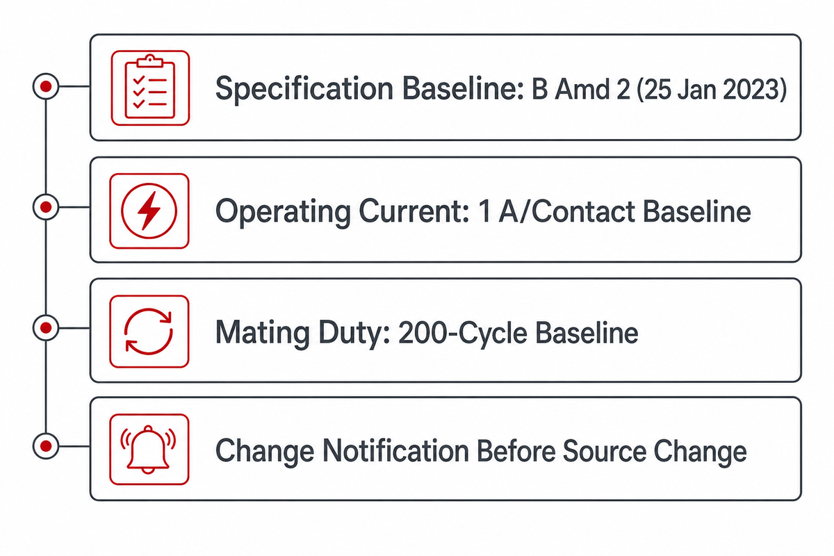
A good RFQ tells engineering, quality, sourcing, and the supplier what must be identical across quotes. The company profile above does not define that request; the requirement-to-control ledger does. MIL-DTL-32139’s acquisition-description structure is the document baseline; the application and assurance fields below close the additional buyer decisions. Copy the table into the request, then replace every placeholder with the controlled application value.
RFQ checklist — copy these into your quote request:
| Parameter | Recommended range | Why it matters | How to verify |
|---|---|---|---|
| Specification baseline | Exact revision/date; currently B Amd 2 (25 Jan 2023) | Prevents moving-baseline quotes | ASSIST capture and PO text |
| Complete PIN | All applicable fields; no blank assumptions | Locks interface and configuration | Drawing-to-PIN review |
| Operating current/voltage | Application-defined; current not above verified 1 A/contact baseline | Avoids misuse of test voltage | Electrical/thermal design review |
| Temperature and dynamic loads | Full application profile in °C, Hz, g and shock pulse | Qualification conditions may not match service | Requirements trace to test report |
| Mating duty | Expected cycles plus margin; compare with 200-cycle baseline | Controls service-life assumption | Maintenance plan and durability evidence |
| Qualification and lot evidence | Current exact-part QPD record plus named lot reports | Separates source status from shipment acceptance | Dated registry check and certificate review |
| Assembly/inspection data | Application-defined unit and lot records | Makes automated controls auditable | Trial, GR&R and data-schema approval |
| Change notification | Before material, process, location, drawing or source change | Protects qualification and configuration status | Contract clause and approval workflow |
Specify the mating accessory, packaging and handling requirements, first-article scope, sampling plan, test-equipment resolution, nonconformance response, record-retention period, and permissible substitutions. For pre-wired products, specify wire specification, gauge, color code, length and tolerance, strip or termination specifications, labeling, continuity, pull-test evidence, and strain relief.
Program purchase clauses can be narrower than the family specification. As project-specific examples—not MIL-DTL-32139 requirements—JPL clause QC136b requires traceability back to the original manufacturer without supply-chain gaps when an order comes through an unauthorized distributor, while JPL clause QC138a imposes selected manufacturer and date-code restrictions on named connector families. An RFQ should identify the actual contractual clauses, authorized-source rule, lot/date-code limits, and evidence package that govern its program rather than importing another project’s restrictions wholesale.
For a DoD acquisition, do not jump from “connector” to automatic coverage by an electronic-parts clause. DFARS 252.246-7008 defines an electronic part as an integrated circuit, discrete electronic component, or circuit assembly. This public-source review does not determine whether a standalone Nano-D connector falls inside that defined-item boundary for a particular contract. Contracting and parts-assurance teams must first confirm the incorporated clauses and item classification. Where the clause does cover the acquired item, paragraph (c) requires risk-based tracking from the original manufacturer through Government acceptance, with inspection, testing, and authentication when that traceability cannot be established. Paragraph (e) flows the clause’s substance into relevant subcontracts unless the subcontractor is the original manufacturer. These controls do not turn QPD status or a lot certificate into delivery-authenticity proof, and they must not be represented as universal MIL-DTL-32139 requirements.
Destination-market material rules are another separate input. UK government RoHS guidance requires technical records and conformity steps for in-scope electrical equipment placed on the Great Britain or Northern Ireland markets, while recognizing exclusions for some military-use or specifically space-bound equipment and different GB/NI regimes. Its business-to-business wording concerns products specifically for research and development; “sold B2B” is not a blanket exemption. Responsibility attaches to the in-scope equipment and the manufacturer, importer, or distributor placing or making it available, so a connector datasheet alone cannot settle the finished-product decision. Identify destination, final equipment, end use, economic-operator role, applicable exclusion or exemption, and required declarations before converting a connector material choice into a market-compliance claim.
United States export controls require a different determination. A MIL-DTL-32139 identity does not assign export jurisdiction, an Export Control Classification Number, license need, or transaction permission. BIS classification guidance says an item subject to the Export Administration Regulations must be classified and that even EAR99 items may require a license because of destination, end user, or end use. If State-versus-Commerce jurisdiction remains uncertain after the applicable review, the DDTC commodity-jurisdiction process provides the formal determination route. Treat export review as transaction-specific compliance work, not as a property inferred from qualification.
If the RFQ includes custom assembly equipment, attach sample parts and a defect taxonomy. Define which characteristic stops the cycle, which requires quarantine, who can override a result, and how recipe changes are approved. For high-reliability work, a pass lamp without traceability is not an evidence package. Connector manufacturers and contract assemblers answering this RFQ carry the reverse burden: proving each control with retained, unit-level records rather than a one-line certificate. For twist-pin contact production specifically, ZEUEE’s Nano twist-pin production equipment page describes one commercial automation option; evaluate its capability claims against the same challenge-set and traceability requirements set out above.
Key takeaway
A Nano-D purchase becomes defensible only when the active baseline, complete PIN, live qualified-source record, lot evidence, application approval and validated production controls point to the same configuration.
Turn the evidence ladder into an assembly brief
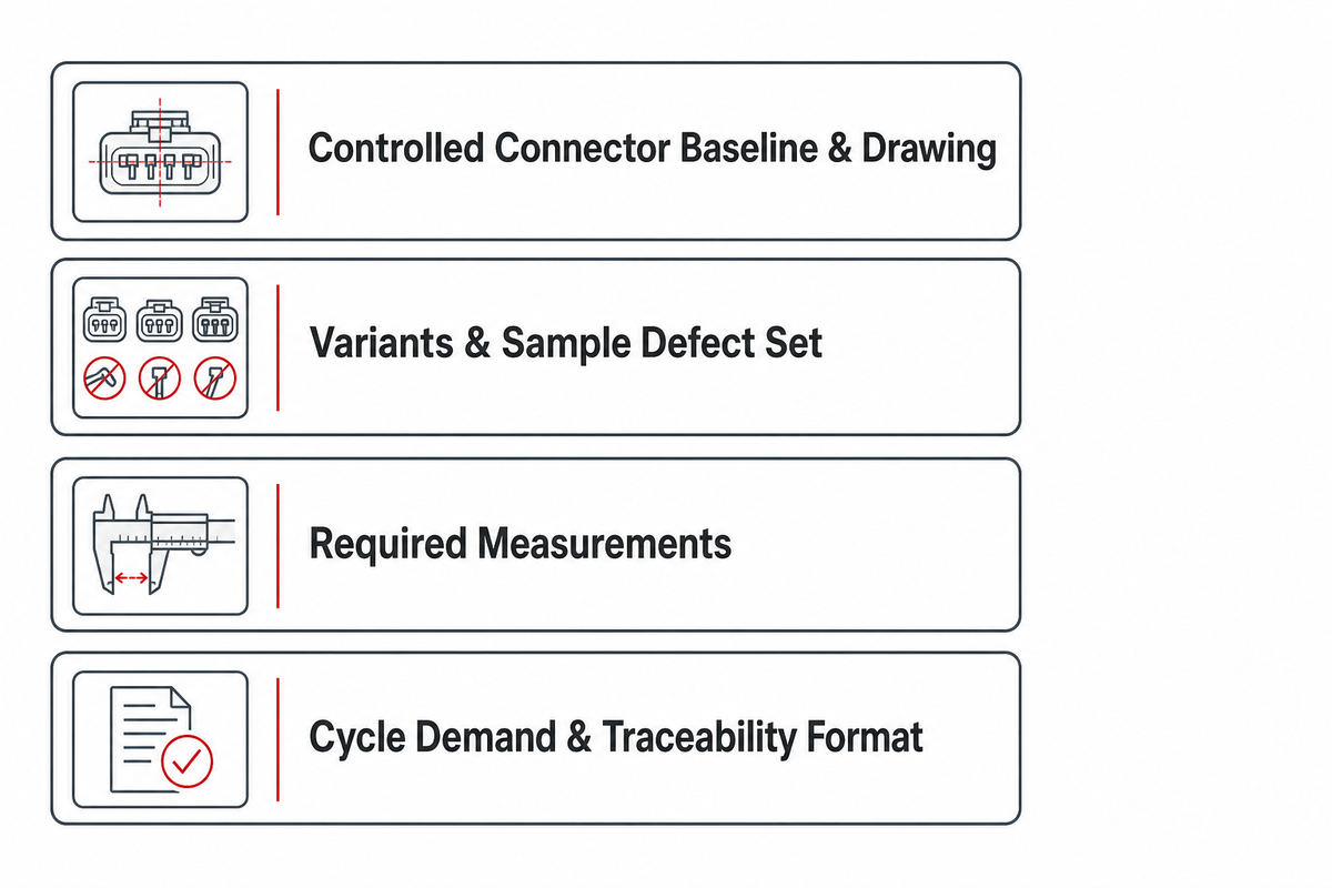
Send ZEUEE your controlled connector baseline, drawing, variants, sample defect set, required measurements, cycle demand and traceability format. An initial discussion can map those inputs to a realistic automation and inspection concept without claiming that one machine recipe fits every Nano-D configuration.
Nano-D Connector FAQ
What is a Nano-D connector?
A Nano-D connector is a rectangular polarized-shell nanominiature connector family used where board area and mass are constrained. MIL-DTL-32139 covers polarized-shell versions for printed circuit boards or cable assemblies with 0.025 in (0.64 mm) contact centers in one contact row.
A family name alone does not establish termination, contact arrangement, environmental limits, or qualification status.
What is MIL-DTL-32139?
MIL-DTL-32139 is a U.S. military detail specification for polarized-shell nanominiature connectors. This review uses revision B with Amendment 2, dated 25 January 2023, as the active baseline. It defines family requirements, tests, PIN structure, qualification and conformance for covered assemblies.
A July 2026 Amendment 3 document is an unapproved initial draft, not the current requirement.
Does “MIL-DTL-32139 style” mean a connector is qualified?
No. “Style” indicates resemblance or design intent, not proof that an exact product/source is currently qualified. Search the complete government PIN in authenticated ASSIST QPD, then match the listed manufacturer, source location, slash sheet, insert and suffixes to the item being quoted. Use QPDSIS and public QPLDOCS as limited supporting snapshots, not substitutes for the official database. Treat qualification, configuration identity, and production-lot conformance as separate evidence lines. Record the lookup date because listings and document baselines can still change.
In this review, public QPLDOCS labels its governing document MIL-DTL-32139A with Amendment 1 even though ASSIST publishes revision B with Amendment 2. That limited public-display mismatch is a reason to verify the official QPD record and contact the Qualifying Activity when acceptance is affected—not a license to choose whichever label is convenient. A supplier name, logo, family-level catalog statement, QPDSIS snapshot, or undated screenshot cannot establish the delivered part’s complete current status by itself.
What is the difference between Nano-D and Micro-D connectors?
Nano-D and Micro-D are different size classes governed by different specifications. Nano-D uses 0.025 in (0.64 mm) contact centers and can reduce envelope and mass. This review uses durability baselines of 200 cycles for Nano-D and 500 cycles for Micro-D. Compare application geometry, mate count, handling, sourcing and complete qualification evidence rather than assuming smaller is better.
Which Nano-D connector documents should a buyer request?
Request the active general-specification revision, exact slash sheet, complete PIN, configuration drawing, mating-half identity, electrical and environmental requirements, a dated authenticated exact-part QPD record, relevant QPDSIS/public snapshots, qualification-retention evidence, Group A or other lot records, unit-level electrical-test results, material and finish certificates, traceability, first-article plan, nonconformance process and change-notification terms. Add program-specific parts assurance and workmanship documents where they apply.
Can Nano-D connector assembly and inspection be automated?
Selected identification, loading, insertion, alignment, electrical testing and visual inspection steps can be automated. Any control plan must be validated on the exact connector, variants and known defect set. A generic vision or force-monitoring capability does not prove Nano-D detection performance. Require measurement-system analysis, challenge samples, stop limits, traceable recipes and retained unit or lot data.
References and Verification Sources
References & Sources: the links below are the public records used for specification, qualification, comparison, workmanship, and inspection-context claims.
- DLA ASSIST/Quick Search, MIL-DTL-32139 document details
- MIL-DTL-32139B with Amendment 2
- DLA MIL-DTL-32139 parent and slash-sheet document index
- DLA Qualified Products Database part search
- DLA MIL-DTL-32139 qualification-information page
- DLA MIL-DTL-32139 single-source solicitations
- QPDSIS-32139, 29 May 2026
- MIL-DTL-32139B Amendment 3 initial draft, 24 July 2026
- DLA EP Study 5935-2026-002, final report
- MIL-DTL-83513H with Amendment 2
- Sandia nano-miniature connector fretting-corrosion study
- RadCube/MAGIC detector-electronics architecture
- NASA Parts Selection List, general requirements
- NASA pure-tin plating prohibition guidance
- NASA MIL-PRF-83513 application notes
- NASA GSFC EEE-INST-002 selection, screening, qualification, and derating
- NASA-STD-8739.4 workmanship standard
- NASA-STD-8739.10 electrical, electronic, and electromechanical parts assurance standard
- JPL QC136b counterfeit-parts avoidance clause
- JPL QC138a connector-sourcing clause
- DLA applications portal migration notice
- US 12,051,251 B2, connector component identification (Harting Electric Stiftung & Co. KG; not ZEUEE)
Qualification-source note: the QPLDOCS link in the reference list is the limited public search surface, not the authenticated ASSIST QPD. Use ASSIST QPD or the Qualifying Activity for an acceptance-critical determination.
Additional scope sources: Defense Standardization Program qualification FAQ; NASA-STD-3001 Volume 2 Revision F record; NASA-STD-8739.10 scope; GSFC-STD-8013 mating and demating controls; NASA-STD-8739.4 connector-life controls; NASA cable-assembly post-installation lesson; DLA MIL-DTL-83513 record; NASA RF-breakdown lesson; DFARS electronic-parts clause and definition; DFARS counterfeit-parts policy; UK government RoHS guidance; BIS item-classification guidance; DDTC commodity-jurisdiction guidance.
Editorial scope: this guide synthesizes public sources checked on 12–13 August 2026. Draft documents and Engineering Practice Study recommendations are labeled as change-watch evidence. DLA announced that its application portal migrated from landandmaritimeapps.dla.mil to weaponssupportapps.dla.mil effective 8 August 2026; preserve access dates and update old-domain bookmarks when checking records. Verify all live DLA records before contracting, design release or acceptance.
WHY WE WRITE THIS
About ZEUEE Engineering Insights
ZEUEE shares technical guides based on real automation project experience. Since 2005, we have designed and manufactured non-standard automation equipment for connector assembly, wire harness production, robotic lines, vision inspection, and smart factory upgrades.
Founded in 2005
20,000 m² production base
120+ specialists
150+ R&D patents
ISO9001:2015 certified




![Automated Screwdriving: Torque & Cycle Time [Guide]](https://zeueeauto.com/wp-content/uploads/2026/10/automated-screwdriving-featured-150x150.png)