Get in touch with Zeyu lntelligent Industrial Company

D-Sub & Micro-D Connector Machine Guide: From Process Control to FAT

Updated August 2026
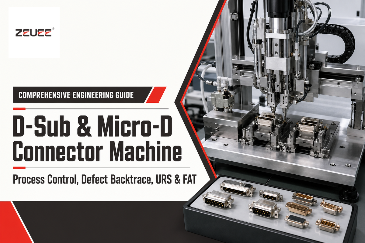
A D-Sub & Micro-D Connector Machine isn’t one universal piece of equipment. It’s a project-defined manufacturing system that prepares, presents, joins, inspects, rejects, and records connector assemblies according to a controlled product definition. Machine boundaries come from the drawing, contact design, incoming condition, required tests, variant mix, and acceptance plan.
D-Sub & Micro-D Connector Machine: define the product revision, station scope, process signals, product tests, and retained evidence before selecting equipment. Completing a cycle proves motion occurred; it doesn’t by itself prove a conforming connector.
Quick project brief
- Content role: manufacturing and validation guide, not a machine quotation page
- Primary inputs: controlled drawings, BOM, revision, samples, and variant matrix
- Core evidence: process signals plus the specified product checks
- Numerical limits: drawing-, specification-, and trial-dependent
- Commercial handoff: the existing ZEUEE D-Sub and Micro-D solution page
Key points
- Connector family names don’t define the production route.
- D-Sub and Micro-D may share some station functions, but shared equipment must be proven with representative parts.
- Force, position, and vision are process evidence; product conformance requires the applicable characteristic and test method.
- Useful factory acceptance testing begins with the user requirement specification, not with supplier-selected demonstration parts.
What a D-Sub & Micro-D Connector Machine Actually Covers
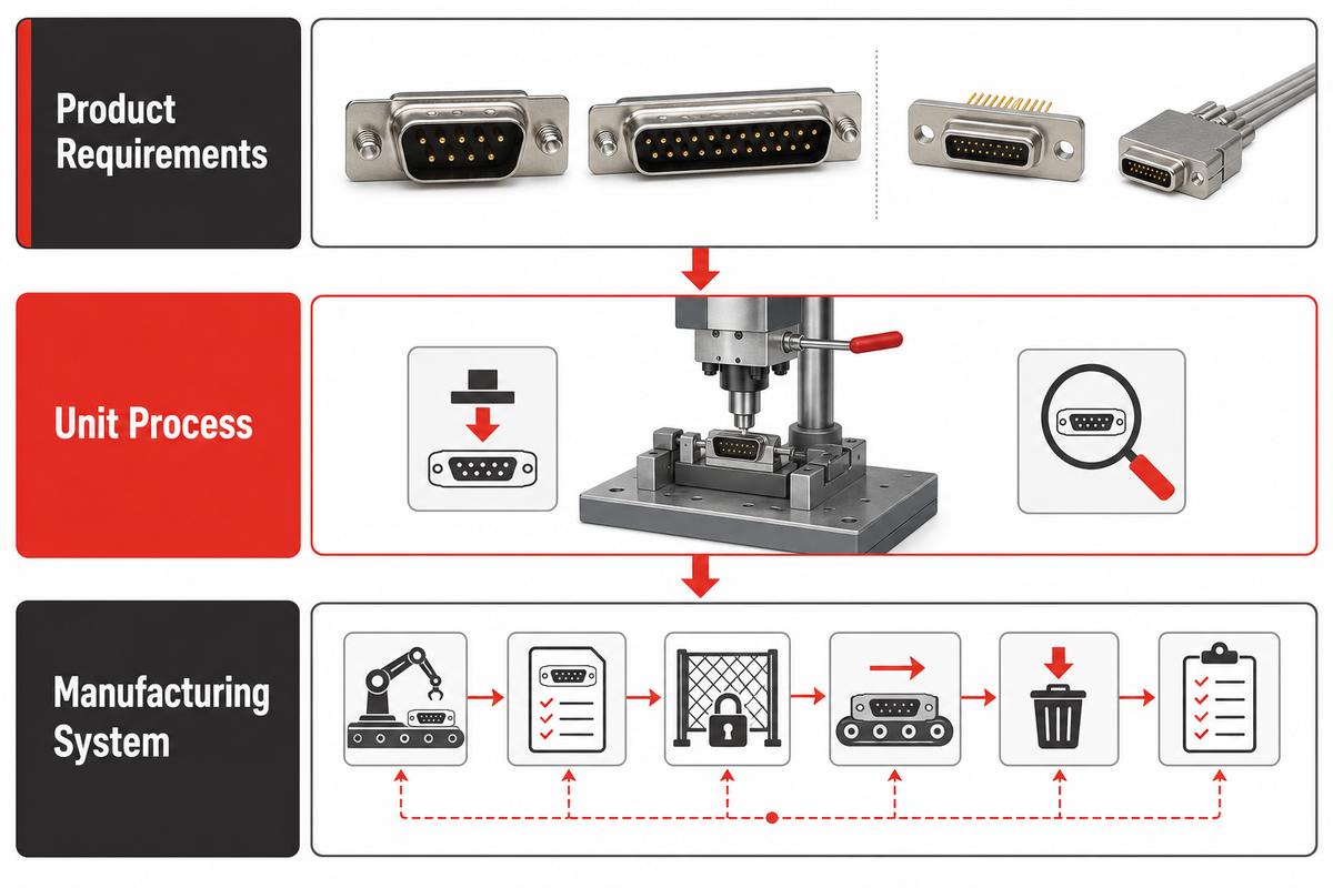
A D-Sub or Micro-D production project can describe three different things: the connector product, one unit process, or a connected manufacturing system. Separating those layers prevents a buyer from comparing a contact-forming machine with a contact-insertion station or a complete line as if they were the same offer.
Product requirements define what must be made. They include the connector drawing, approved materials, contact arrangement, termination route, housing or shell features, markings, and acceptance characteristics. At the unit-process layer, a bounded task may include contact preparation, crimping, soldering, insertion, shell assembly, visual inspection, electrical testing, or marking. At system level, selected processes connect through part transfer, recipes, interlocks, reject handling, and trace records.
| Layer | Question it answers | Evidence needed | Mistake if omitted |
|---|---|---|---|
| Connector product | What must the finished assembly meet? | Drawing, BOM, revision, applicable specification, inspection plan | A generic machine is quoted against an undefined product |
| Unit process | What physical or inspection operation is performed? | Input condition, output characteristic, tool and test method | One station is assumed to complete unrelated operations |
| Manufacturing system | How do parts, decisions, rejects, and records move? | Interface map, recipe logic, trace fields, containment route | Stations work separately but the line cannot control the product |
What is a Micro-D connector?
Micro-D is a polarized-shell microminiature rectangular electrical connector family. MIL-DTL-83513 is the official U.S. defense specification family often associated with qualified Micro-D products. Labels such as “Micro D-Sub” or “mil-spec” are search shorthand, not complete production definitions. Cable plugs and PCB receptacles can impose different handling and circuit-test interfaces even when both belong to the same family. Connector requirements come from the specification; it doesn’t prescribe a universal automation layout. For shell sizes, slash sheets, terminations, part numbers, and sourcing questions, use the dedicated Micro-D connector buyer guide.
Decision point: ask every supplier to label each quoted item as product tooling, a unit-process station, shared line infrastructure, or an excluded operation. That single classification removes many scope disputes before layout work begins.
D-Sub vs Micro-D: What Changes on the Factory Floor
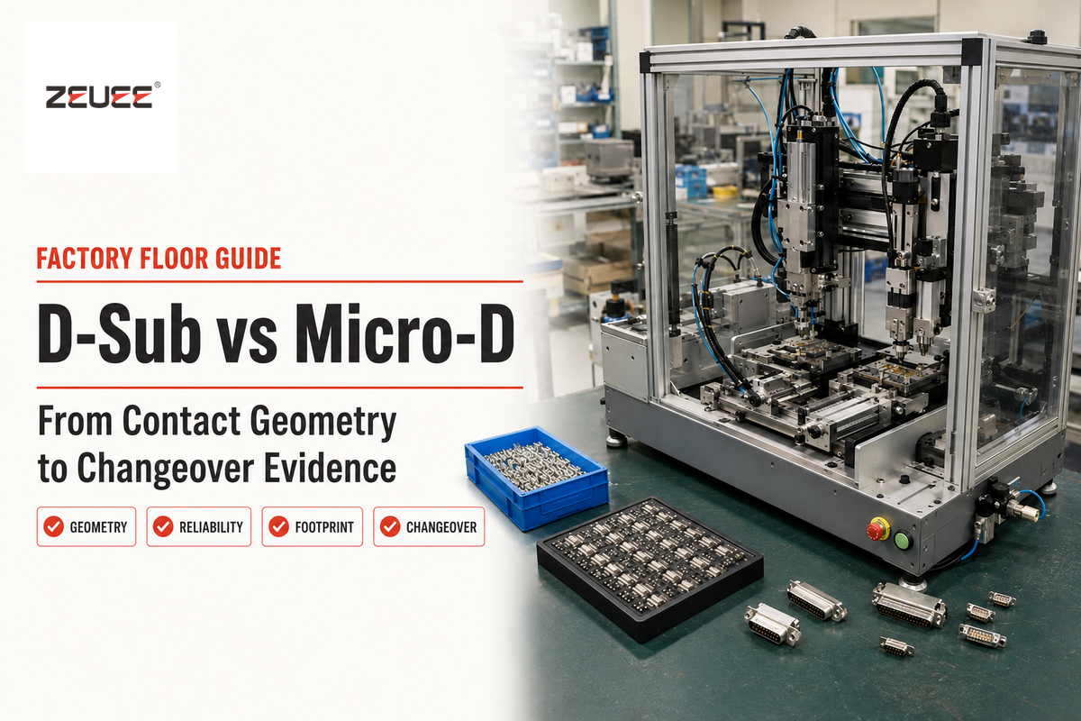
D-Sub and Micro-D manufacturing should be compared by process consequences, not by claims that one family is simply larger, smaller, or better. Pitch, contact construction, access, housing datum, termination, shielding, and inspection visibility affect presentation, tooling, sensor choice, and the proof required after assembly.
Standard D-Sub assemblies may arrive as loose contacts, reeled contacts, housings, metal shells, backshells, cable, PCB parts, or partially finished subassemblies. Micro-D projects may use a different contact design, tighter access around high-density features, and product-specific handling limits. Yet the family label still doesn’t reveal whether contacts are crimped, soldered, prewired, formed, inserted, overmolded, or supplied as a finished insert. Drawings and BOMs settle that question.
| Manufacturing variable | Machine implication | Evidence to request | Limitation |
|---|---|---|---|
| Incoming part format | Feeder, tray, reel, carrier, or manual load strategy | Packaging samples and incoming-condition specification | A clean sample tray does not prove bulk presentation |
| Contact geometry | Grip, guide, forming, insertion, and damage-detection method | Current contact drawing and approved material condition | Contact style cannot be inferred from the family name |
| Housing or shell datum | Nest location, orientation, approach path, and fixture repeatability | Datum scheme and tolerance stack from the product drawing | A cosmetic surface may not be a functional datum |
| Joining route | Crimp, solder, insertion, forming, or external operation | Process specification and approved tooling | One route cannot be assumed for all variants |
| Inspection access | Camera angle, lighting, probe access, gauge, or destructive sample test | Characteristic list and measurement method | Visibility does not prove retention or electrical performance |
| Variant changeover | Change parts, recipes, gauges, verification, and access control | Variant matrix and planned change sequence | A shared frame does not guarantee a validated shared process |
Are all D-Sub connectors processed the same way?
No. D-Sub describes a family, not a single production recipe. Standard-density, high-density, mixed-layout, board-mount, cable, crimp, and solder configurations can require different incoming materials, tools, access, checks, and reject rules. Quotes should therefore identify the exact assemblies and revisions covered rather than state only “D-Sub compatible.”
Contact selection needs the same caution. If the project must compare twist-pin, hyperboloid, or stamped contacts, keep that decision in a separate technical track. ZEUEE’s existing connector contact-types guide covers that choice without turning this machine guide into a duplicate product-comparison page.
Build a Family-to-Station Matrix Before Choosing Equipment
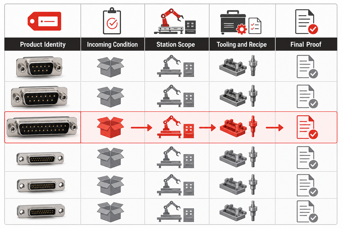
The Family-to-Station Matrix is a controlled map that binds every approved connector variant to its required operations, tooling, recipe, checks, and exclusions. It exposes where a shared station is plausible, where dedicated hardware is needed, and where the supplier still lacks enough evidence to make either claim.
Begin at the drawing rather than the machine brochure. Follow the material from incoming identity and presentation through preparation, joining, seating, inspection, reject confirmation, and record creation. Some stages may remain manual or external. That’s acceptable when the interface, owner, and acceptance evidence are explicit.
| Matrix field | What to record | Why it changes the design | Proof at trial |
|---|---|---|---|
| Product identity | Family, part number, drawing and BOM revision | Prevents recipe use on the wrong assembly | Trace record matches physical sample |
| Incoming condition | Packaging, orientation, cleanliness, prework, allowable variation | Controls feeder and error-proofing risk | Representative production packaging runs without special handling |
| Station scope | Mandatory, optional, manual, external, and excluded operations | Prevents hidden process gaps | Each handoff has an accepted input and output |
| Tooling and recipe | Nest, gripper, guide, applicator, program, gauge | Determines changeover and control strategy | Tool and recipe identity are retained with results |
| In-process check | Presence, orientation, position, force, image, interlock | Defines immediate detection and containment | Known good and known defect conditions are distinguished |
| Final proof | Specified product characteristic and test method | Separates process completion from conformance | Result agrees with the approved acceptance method |
| Changeover item | Physical change part, software recipe, gauge, first-piece check | Controls mixed-variant risk | Changeover is executed and rechecked under the trial plan |
| Not in scope | Operations and characteristics owned elsewhere | Prevents implied capability | External handoff and owner are documented |
| Open assumption | Unproven presentation, tolerance, test, or interface | Identifies what can still change cost and schedule | Assumption is closed, qualified, or accepted as a limitation |
Can one machine handle both D-Sub and Micro-D assemblies?
One platform may share controls, frames, data systems, or selected stations across both families, but that’s a testable proposal rather than a default fact. Representative parts must demonstrate presentation, tooling access, sensor resolution, recipe protection, changeover, inspection, and reject handling for every included variant. An untested family remains outside the validated scope.
Key takeaway
Shared hardware isn’t the same as a shared validated process. Each matrix must show which variant, station, tool, recipe, check, and final proof were actually demonstrated.
Use a Defect Backtrace Map Instead of Adjusting the Last Station
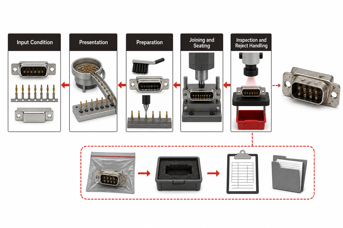
The Defect Backtrace Map starts with an observed defect indication, then walks upstream through input condition, presentation, preparation, joining, seating, inspection, and reject handling. Its purpose is containment and troubleshooting. It doesn’t declare root cause until the suspected condition is reproduced or otherwise confirmed.
Shallow contacts, for example, can arise from an incorrect housing datum, a damaged contact, incomplete preparation, tooling wear, obstruction, a motion limit, or a false inspection rule. Increasing insertion force may hide one defect indication while damaging the product or tool. Safer containment starts by preserving the failed sample, identifying the product and recipe record, reviewing the process trace, and confirming the suspected station with an approved test.
| Observed defect indication | Check upstream | Confirmation evidence | Do not conclude from |
|---|---|---|---|
| Missing or wrong contact | Part identity, feeder output, orientation, pick confirmation, recipe | Trace record plus retained image or physical audit | Cycle-complete signal alone |
| Bent or damaged contact | Incoming condition, guide path, grip point, interference, reject handling | Pre/post inspection and controlled reproduction | Final camera view that cannot see the damage plane |
| Shallow or deep seat | Datum, part stack, tool position, obstruction, insertion trace | Approved depth or position measurement | Actuator end position without product measurement |
| Weak termination | Material identity, preparation, tool/setting, wear, process verification | Specified retention or pull method and traceable sample | Visual appearance alone |
| Continuity failure | Wrong contact, damage, termination, incomplete seat, test interface | Controlled electrical test plus physical investigation | Mechanical force trace alone |
| Contamination or debris | Incoming parts, tooling, handling, cleaning, enclosure, rework | Inspection against the approved cleanliness criterion | A normal cycle time |
| Record/part mismatch | Scanner, queue, recipe selection, label, rework and data interface | End-to-end challenge with mixed identities | A database row that was not tied to the physical part |
The NASA workmanship standard for crimping and interconnecting hardware provides a useful control pattern: verify the process, retain traceable records, inspect the finished work, and treat production made before a failed verification as suspect. Its mission-hardware rules and numeric criteria aren’t universal commercial limits, but the evidence logic is transferable.
Do
- Preserve the failed part and its trace record
- Check upstream inputs before changing the final station
- Confirm a suspected cause with the approved method
- Contain other parts made under the same suspect condition
Don’t
- Raise force to make a seating defect indication disappear
- Treat a vision pass as proof of hidden characteristics
- Mix setup scrap with unexplained production rejects
- Close the investigation without a reproducible finding
Separate Process Signals from Connector Conformance
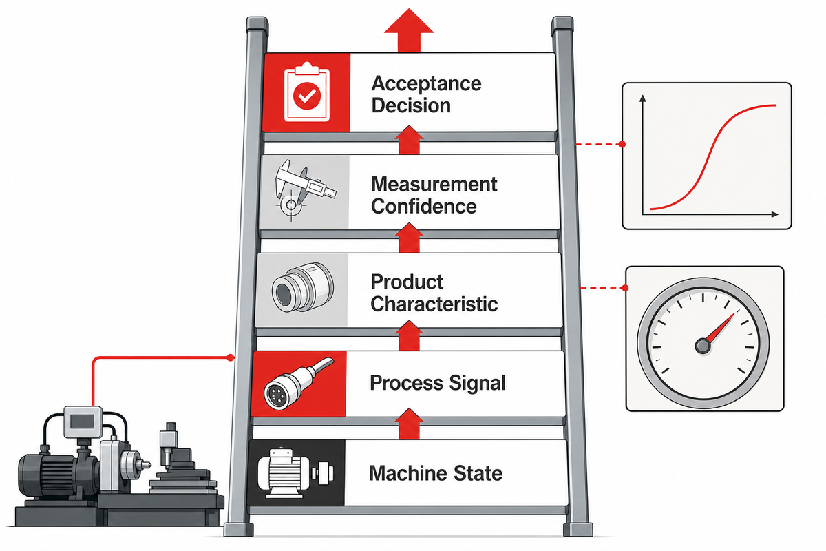
The Signal-to-Conformance Ladder separates five levels of evidence: machine state, process signal, product characteristic, measurement confidence, and acceptance decision. Moving up the ladder requires a defined relationship between levels. A force curve can expose process change, but it can’t silently become proof of every electrical, dimensional, retention, shielding, or durability requirement.
- Confirm machine state — identify the loaded recipe, product, tool, interlocks, and operating mode.
- Capture the process signal — retain the relevant force, displacement, time, current, torque, image, or position result.
- Measure the product characteristic — apply the approved check for seat, retention, continuity, resistance, dimensions, marking, or another specified output.
- Qualify measurement confidence — control calibration or verification state, repeatability, reproducibility, stability, sampling, and trace linkage.
- Make the acceptance decision — compare the result with the current drawing, applicable detail specification, approved method, limit, retest rule, and disposition route.
IEC 60512-1:2018 is especially helpful here because it describes a generic framework for connector tests and measurements, including preparation, testing, requirements, documentation, and calibration context. Its publication page also makes the boundary clear: the relevant detail product specification defines the required tests, severity, permissible limits, and any special procedures.
Measurement-system readiness is a separate question from machine capability. NIST Gauge R&R guidance characterizes production measurement error through repeatability, reproducibility, and stability. If the gauge can’t distinguish product variation from measurement variation under the intended conditions, its result shouldn’t control acceptance merely because it’s displayed by the machine.
Engineering note
Specify what each signal proves, what it doesn’t prove, who owns the acceptance limit, and how the result is tied to the physical connector. Leave numerical windows blank until the approved source and representative trial establish them.
| Evidence | Can support | Cannot prove alone | Acceptance owner |
|---|---|---|---|
| Recipe/tool identity | Correct controlled setup was selected | Product was assembled correctly | Process engineering and quality |
| Force-position trace | Process pattern and limit challenge | Electrical, retention, or dimensional conformance | Process owner with product correlation |
| Vision result | Visible presence, orientation, position, or marking rule | Hidden contact condition or electrical performance | Quality owner of the visible characteristic |
| Continuity test | Defined electrical path at the test condition | Mechanical retention or long-term stability | Electrical test owner |
| Retention or pull result | Specified mechanical characteristic for the tested sample | Every untested unit unless the plan permits inference | Product quality and specification owner |
| Trace record | Product, recipe, tool, time, result, and disposition linkage | Accuracy of a measurement method | Quality system and data owner |
Write the URS Before Designing the Sample Run and FAT
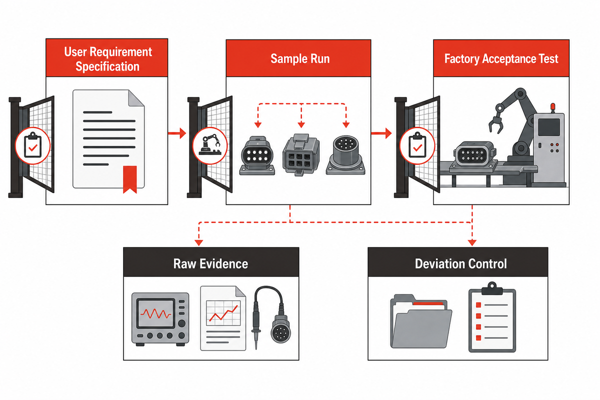
A user requirement specification should define the product, interfaces, control obligations, and acceptance method before representative samples are sent. Next, the sample run tests those requirements, while the factory acceptance test records whether the agreed scope passed. Reversing that order turns a supplier demonstration into an undefined acceptance event.
Your URS doesn’t need to dictate every mechanical design choice. It does need to identify the controlled drawing and BOM revisions, included variants, incoming part condition, required operations, product characteristics, applicable standards or test methods, trace fields, reject and rework policy, changeover expectations, utilities, access roles, documentation, training, maintenance, and approval owners.
Sample selection deserves the same discipline. Include normal production parts and the boundary conditions that the equipment is expected to handle. Cover the intended variants, packaging, lots, and incoming conditions. Reserve enough material for setup, the controlled run, justified retests, retained samples, and safe challenge pieces where the quality plan permits them. Supplier-selected ideal parts can’t establish a production window that excludes the buyer’s difficult but allowed conditions.
In the NIST peg-in-hole project, recorded inputs and orientations plus a project-specific rule illustrate the structure of an explicit insertion trial. Its numeric force threshold belongs only to that experiment. What transfers is the need to bind the input condition, recorded signal, completion definition, and outcome before reviewing results.
| FAT field | Question to close | Required record | Failure if omitted |
|---|---|---|---|
| Preconditions | Are drawings, parts, tools, software, gauges, and utilities in the agreed state? | Signed readiness list and revision identifiers | Results cannot be tied to a controlled setup |
| Sample matrix | Which normal, boundary, and variant conditions are represented? | Traceable sample list and run order | A narrow demonstration is mistaken for full scope |
| Pass/fail rule | Which source and method control each decision? | Acceptance matrix with owner and limit source | Results are debated after the run |
| Stop rule | Which event stops the trial or places production at risk? | Approved containment and escalation instruction | Suspect parts continue through the test |
| Retest rule | When is a retest valid, and what does it replace? | Reason, authorization, sample identity, original and new result | Selective retesting hides instability |
| Reject challenge | Can known allowed challenges be detected and contained? | Challenge definition and observed disposition | Inspection is never shown to recognize failure |
| Raw evidence | Can the summary be traced to images, signals, tests, and identities? | Exported raw records plus summary | Only a pass statement remains |
| Deviation control | Who may accept a change from the protocol? | Deviation, reason, impact, owner, and disposition | The test scope changes without accountability |
| Sign-off | Who accepts results and who owns open actions? | Signed result and open-action register | Shipment proceeds with unresolved assumptions |
Quality rule: don’t ask a supplier to “prove the machine works” as one line item. Assign each requirement a verification method, evidence format, owner, and disposition rule. That converts a subjective demonstration into an auditable FAT.
Control Traceability, Changeover, and Revalidation After Handover
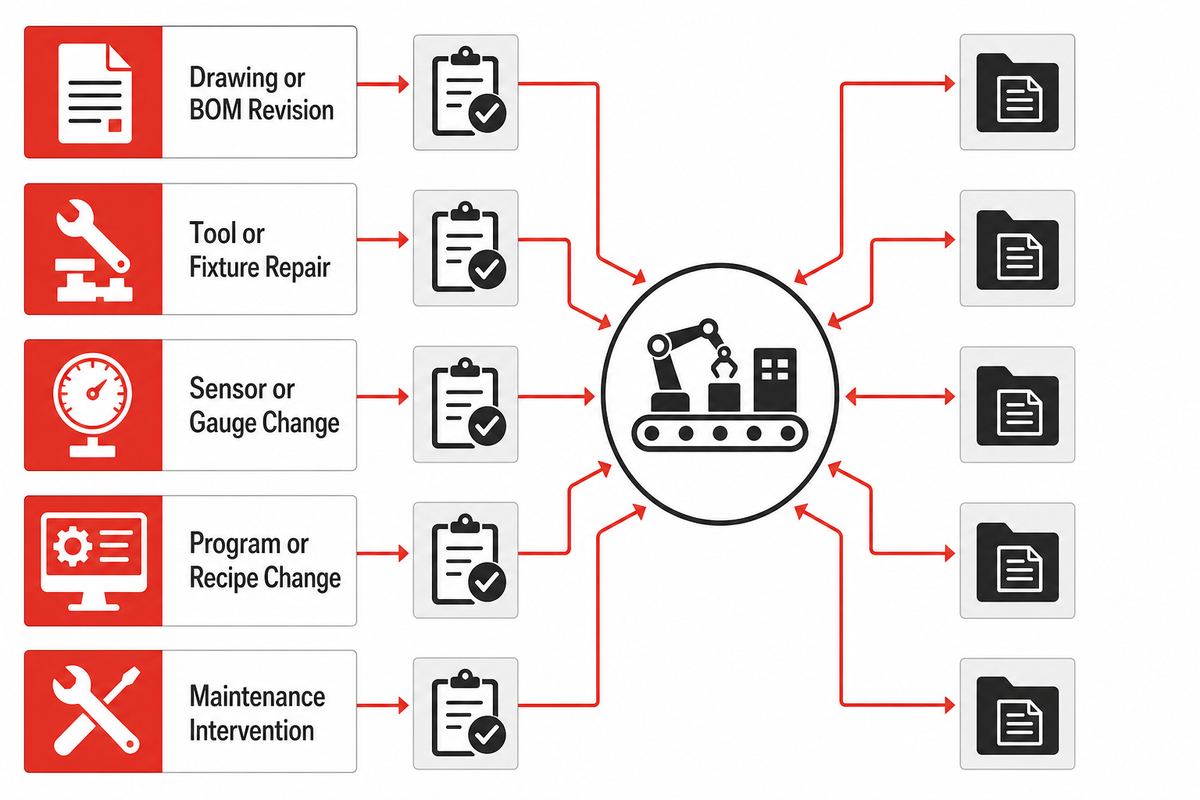
Production control continues after FAT. Traceability must connect the physical connector to its product revision, incoming lot where required, tool, recipe, process result, inspection result, time, and disposition. Changeover must then protect that relationship when fixtures, recipes, materials, sensors, or product revisions change.
GSFC’s flight connector mating standard offers a tightly scoped example of procedural control: training, tool readiness, inspection, and mate/demate records are treated as part of the operation. Commercial production has a different risk and compliance context, but the principle is relevant: a physical action without identity, authorization, and record control is difficult to audit later.
| Change | Review before release | Evidence to retain | Possible revalidation scope |
|---|---|---|---|
| Drawing or BOM revision | Fit, process, characteristic, program, and tooling impact | Change assessment and approved revision | Affected stations and product checks |
| Incoming material or supplier | Presentation, material condition, tolerances, cleanliness | Qualified material identity and trial result | Feed, handling, joining, and inspection correlation |
| Tool or fixture repair | Datum, wear surface, alignment, setting, identification | Repair record, verification, and first-piece result | Tool-dependent process and product characteristics |
| Sensor or gauge change | Range, setup, software, measurement correlation | Calibration or verification and correlation record | Measurement confidence and decision limits |
| Program or recipe change | Affected motions, logic, limits, data, reject path | Version, authorization, test result, rollback plan | Changed functions and interfaces |
| Maintenance intervention | Parts replaced, settings disturbed, guarding and interlocks | Maintenance and release-to-production check | Restart checks tied to the intervention |
When should a dedicated connector line be delayed?
Delay a dedicated line when drawings are unstable, allowed incoming variation is unknown, parts can’t be presented consistently, included variants are missing from the sample set, acceptance characteristics are undefined, or the rework and containment path has no owner. Those conditions prevent a meaningful machine specification; they don’t become easier after hardware is built.
Possible interim routes include controlled manual tooling, a semi-automatic fixture, modular stations, flexible robotics, supplier-process stabilization, or a design-for-assembly change. High mix or low volume alone doesn’t decide the case. Whether the selected route can control the real variants and produce the evidence the buyer needs without locking unresolved assumptions into dedicated tooling is the deciding question.
Build a URS-to-FAT Evidence Pack for Supplier Comparison
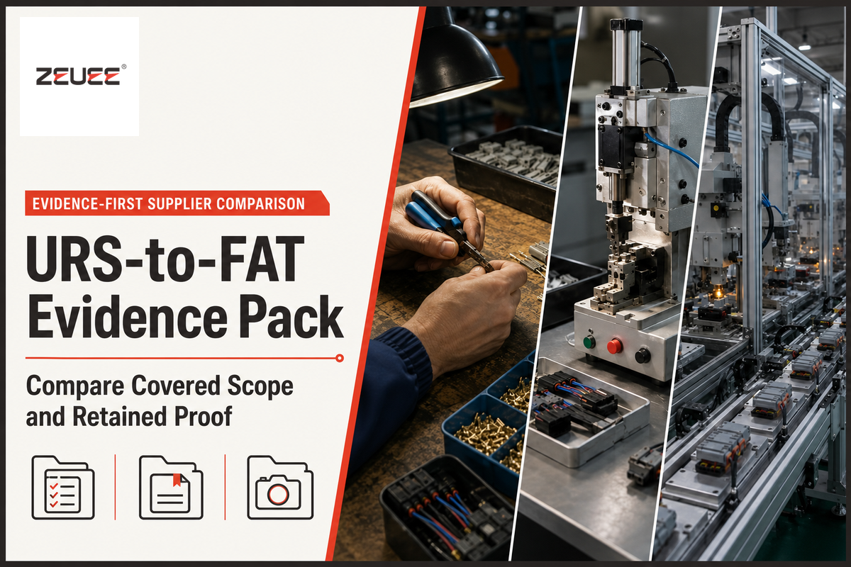
The URS-to-FAT Evidence Pack keeps requirements, samples, supplier assumptions, trial results, and acceptance records in one controlled chain. It lets buyers compare proposals by covered scope and proof rather than by broad capability language. Missing fields remain visible as open assumptions instead of disappearing inside a quotation.
You can copy the following fields into an RFQ. Replace every placeholder with a project-specific value or an explicit “not applicable.” Don’t request an invented recommended range when the governing value must come from your drawing, product specification, test method, or validated trial.
RFQ checklist — copy these into your quote request:
| Parameter | Project-specific value | Why it matters | How to verify |
|---|---|---|---|
| Product scope | Part numbers, drawings, BOMs, revisions | Defines what the equipment must make | Controlled document list |
| Incoming condition | Packaging, orientation, prework, allowed variation | Determines presentation and error-proofing | Run production-representative supplies |
| Included operations | Mandatory, optional, manual, external, excluded | Closes the process boundary | Station and handoff review |
| Quality characteristics | Characteristic, source, method, limit, sampling | Defines conformance evidence | Acceptance matrix challenge |
| Variants and changeover | Variant matrix, change parts, recipes, checks | Determines shared and dedicated scope | Observed representative changeover |
| Traceability | Required IDs, signals, tests, exports, retention | Ties evidence to the physical product | End-to-end identity challenge |
| Sample run and FAT | Samples, preconditions, pass/fail, retest, stop, sign-off | Prevents post-test negotiation | Approved protocol and raw records |
| Lifecycle deliverables | Manuals, backups, training, spares, maintenance, change control | Protects the process after handover | Document and handover audit |
Once this evidence pack is stable, review ZEUEE’s D-Sub and Micro-D connector production-line solution for equipment-specific capabilities and commercial discussion. Keeping that handoff on the solution page prevents this guide from competing for the same quotation intent.
Have drawings and representative samples ready?
Send the product revisions, variant matrix, incoming conditions, and proposed acceptance evidence. ZEUEE’s team can then discuss a bounded automation scope instead of a generic machine request.
Frequently Asked Questions
What are the key manufacturing differences between D-Sub and Micro-D connectors?
Key differences concern presentation, contact handling, datums, joining access, inspection, tooling, and changeover, not a simple size ranking.
Start with the controlled drawing and BOM for each assembly. D-Sub and Micro-D projects can use different contact designs, housing or shell datums, termination routes, access conditions, packaging, and product tests. Those differences change the feeder, nest, gripper, guide path, camera view, joining tool, gauge, recipe, and reject route. Family-level descriptions don’t establish a process window. Suppliers should map every included revision to its station scope and show which parts actually supported the proposed tooling and inspection method.
Are all D-Sub connectors processed the same way?
No. D-Sub is a connector family; the actual process depends on the assembly and quality plan.
No. Packaging, termination, tooling access, inspection features, and final tests can differ. Each proposal should list the exact part numbers, revisions, included operations, and exclusions.
What is a Micro-D connector?
Micro-D denotes a polarized-shell microminiature rectangular electrical connector family.
MIL-DTL-83513 contains product-specific requirements often associated with qualified Micro-D connectors. It doesn’t create one universal manufacturing line or machine setting. Automation still depends on contact design, termination, incoming condition, drawing limits, inspection method, and variant scope.
Can one machine handle both D-Sub and Micro-D assemblies?
Possibly, but only demonstrated stations and variants belong to the validated shared scope.
Possibly. Controls, data, frames, or selected operations may be shared. Representative trials must still prove presentation, tooling access, sensor resolution, recipes, changeover, product checks, and reject handling for every included assembly.
What evidence should a connector-machine FAT include?
Useful FAT evidence connects controlled preconditions and traceable samples to raw results and signed acceptance.
Retain the approved product and sample list, incoming conditions, tool and recipe identity, raw process signals, specified product-test results, reject challenges, deviations, dispositions, and sign-off. Before the run, define pass/fail limits and their source, stop and retest rules, evidence format, and approval owners. Keep unresolved assumptions in an action register with an owner and due date; don’t convert them into an unconditional pass or hide them inside the summary report.
How this guide was prepared
This article separates ZEUEE’s commercial D-Sub and Micro-D solution from the engineering evidence a buyer needs before quotation. It was prepared from current official connector, workmanship, measurement, and robotic-insertion sources, then reviewed against ZEUEE’s existing Micro-D and contact-type articles to avoid duplicating their product-selection role.
For company identity and automation scope, see ZEUEE’s company profile.
References & Sources
- MIL-DTL-83513 specification record; Defense Logistics Agency ASSIST
- NASA-STD-8739.4A Workmanship Standard; National Aeronautics and Space Administration
- IEC 60512-1:2018; International Electrotechnical Commission
- Gauge R&R Studies; National Institute of Standards and Technology
- Peg-in-Hole Data; National Institute of Standards and Technology
- GSFC-STD-8013 Flight Cable and Connector Mating Standard; NASA Goddard Space Flight Center
WHY WE WRITE THIS
About ZEUEE Engineering Insights
ZEUEE shares technical guides based on real automation project experience. Since 2005, we have designed and manufactured non-standard automation equipment for connector assembly, wire harness production, robotic lines, vision inspection, and smart factory upgrades.
Founded in 2005
20,000 m² production base
120+ specialists
150+ R&D patents
ISO9001:2015 certified
![Automated Screwdriving: Torque & Cycle Time [Guide]](https://zeueeauto.com/wp-content/uploads/2026/10/automated-screwdriving-featured-150x150.png)