Get in touch with Zeyu lntelligent Industrial Company

Blind Mating Connector Machine Guide: From Tolerance Stack to Acceptance

Updated August 2026
A Blind Mating Connector Machine presents, orients, inserts, seats, checks, and records connector parts that may later mate without direct visual alignment. Self-aligning features help only inside a defined mechanical envelope. Sound projects still need controlled datums, an approved approach path, force and position limits, defect checks, and a sample-run acceptance method tied to the selected connector family.
Use this engineering guide to define the evidence before requesting equipment. When drawings, parts, and acceptance rules are ready, use the linked solution page for machine-specific discussion. No single insertion force, allowable offset, trial quantity, cycle rate, or pass threshold applies across all blind-mate connector designs.
Project inputs to freeze first
- Connector and contact drawing revisions
- Fixed and floating datums through the complete assembly
- Approved part variants and incoming-part conditions
- Insertion, seating, retention, and functional test methods
- Required records, reject rules, and sign-off owners
What a Blind Mating Connector Machine Actually Automates
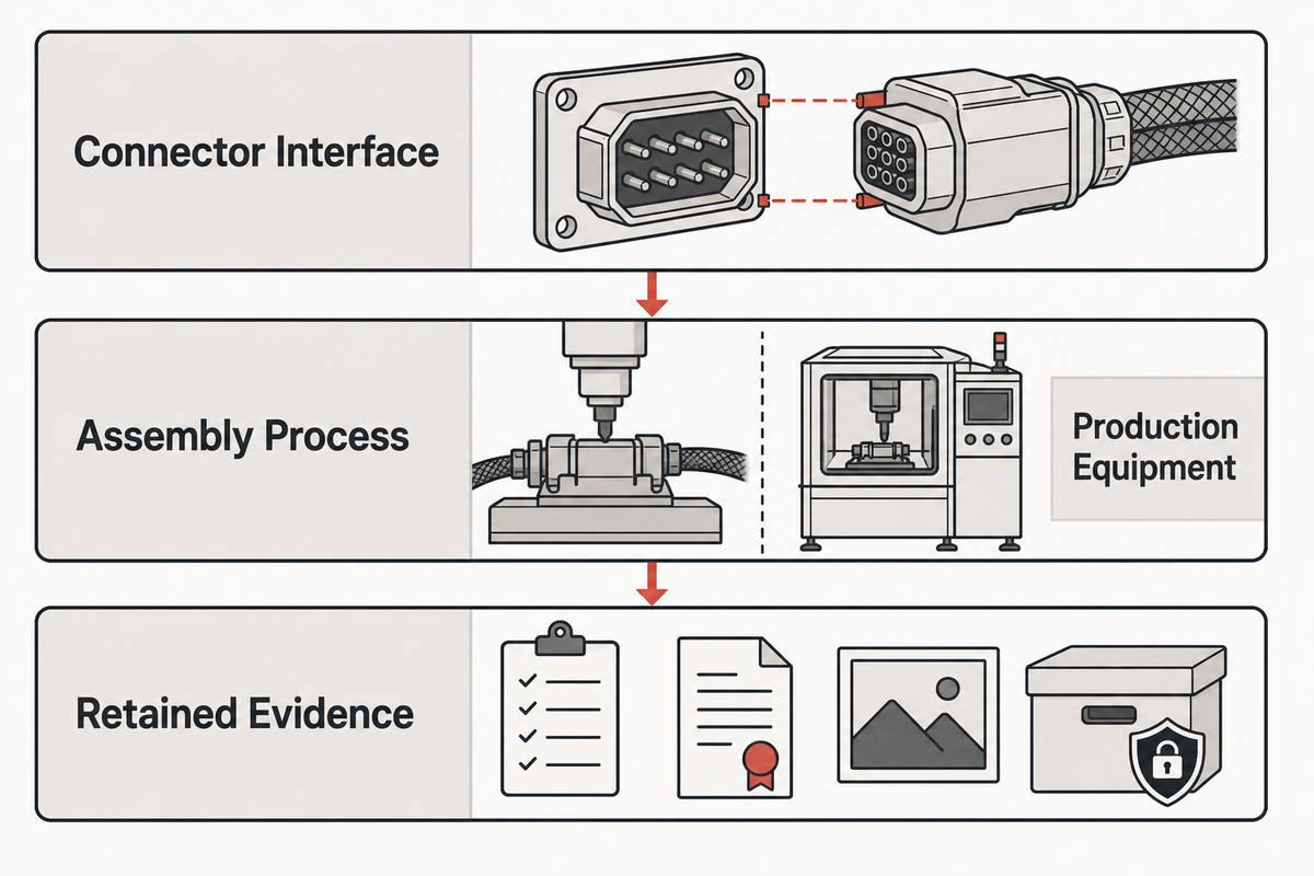
The machine belongs to the production process, not to the connector interface itself. Its job is to turn loose or pre-terminated components into a verified assembly through five controlled functions: present the part, confirm its identity and orientation, insert it along a defined path, verify the result, and route good and rejected assemblies separately.
Search results often mix three objects. First, a blind-mate connector is an interface designed to engage where the operator cannot directly see or manually guide both halves. Second, an assembly process installs contacts or connector elements into housings, panels, boards, or carriers. Third, production equipment controls that assembly process and retains evidence. IEC 60512 provides connector test and measurement methods, but the applicable tests and limits still depend on the connector specification and project.
- Present — separate and deliver the correct component without damage.
- Orient — confirm part number, keying, polarity, and contact direction.
- Insert — control alignment, motion, speed, force, and final position.
- Verify — check the product characteristics required by the acceptance plan.
- Record — associate the recipe, result, reject reason, and retained evidence with the assembly.
What is a blind mate connector?
Blind mate connectors are plug-and-receptacle interfaces intended to engage when direct visual alignment or hand guidance is restricted. Guide pins, lead-ins, shells, or floating mounts may correct a bounded initial mismatch before sensitive contacts fully engage. Those features reduce alignment risk; they don’t remove it. Machine or host-product geometry must still place the halves inside the connector’s specified capture range, protect the mating surfaces, and avoid using insertion force to overcome a datum error. Connector families differ in guidance sequence, contact type, mounting method, and verification needs.
Projects concerned mainly with general contact insertion choices can start with the pin insertion machine selection guide. Blind-mating projects add a system-level alignment question: which feature guides first, and what must already be aligned when it does?
From Float Stack to Insertion Window
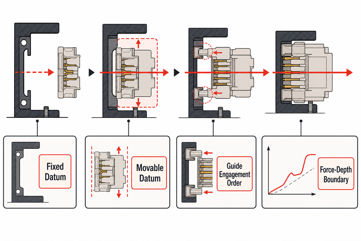
Self-alignment is a bounded correction mechanism, not spare tolerance for every fixture and component. Project teams must trace variation from the feeder, nest, housing, contacts, guides, and actuator to the final seat. Only then can they define an approach window in which guide features engage before damaging loads reach the functional contacts.
Trace the useful datum chain as: feeder location → pickup or transfer datum → nest datum → housing location → contact location → guide engagement → final seat. Public blind-mate interface specifications illustrate why alignment is handled at system level: a connector may include radial and axial freedom while the surrounding structure still has its own alignment and mounting requirements. For real projects, the selected supplier drawing remains the controlling source.
What is a self-mating connector?
Self-mating or self-aligning connectors use geometry or compliant mounting to guide two halves toward the correct mating position after they enter a defined capture region. Such language doesn’t mean that the halves can approach from any angle or offset. Guide features must engage in the intended order, and the remaining mismatch must stay within the connector’s published envelope. For machine design, the critical question isn’t whether the connector “floats,” but which component floats, relative to which datum, at what stage, and how that movement is confirmed during acceptance.
8-Field Float-to-Force Envelope
The Float-to-Force worksheet exposes the hidden bottleneck between nominal alignment and measured insertion force. Engineering owns the geometry; quality owns the evidence method; production owns part presentation; procurement must make sure competing suppliers price the same boundary. Fill every value from controlled drawings, approved test methods, or a witnessed sample run.
| Envelope field | Project evidence | Decision it controls | If omitted |
|---|---|---|---|
| Fixed datum | Assembly and fixture drawing | Nest and measurement reference | Offsets become incomparable |
| Movable datum | Connector drawing and physical sample | Where controlled float is permitted | Fixture may restrain the intended float |
| Initial X-Y offset | Worst-case tolerance stack | Required capture region | Nominal samples hide edge conditions |
| Axial approach window | Drawing and motion study | Start of guided engagement | Contacts may load before guides |
| Angular allowance | System stack and supplier limit | Nest float and approach path | Force rises for the wrong reason |
| Guide engagement order | Section drawing and trial video | Collision prevention | Sensitive features become guides |
| Force-depth boundary | Approved method and samples | Process stop and reject logic | A jam can look like a seat |
| Final-seat definition | Product requirement and gauge plan | Acceptance signal | Cycle complete substitutes for proof |
| Stop criteria | Risk review and test protocol | Part and tooling protection | Abnormal loads continue unchecked |
Engineering note: Don’t borrow a float value or force band from another connector series. Mounting, plating, contact count, lubrication, temperature, cable load, and accumulated manufacturing variation can all change the result. If the system stack sits outside the connector’s verified capture region, fixture flexibility or a product-design change may be needed before equipment sourcing.
Which Assemblies Fit This Automation Approach?
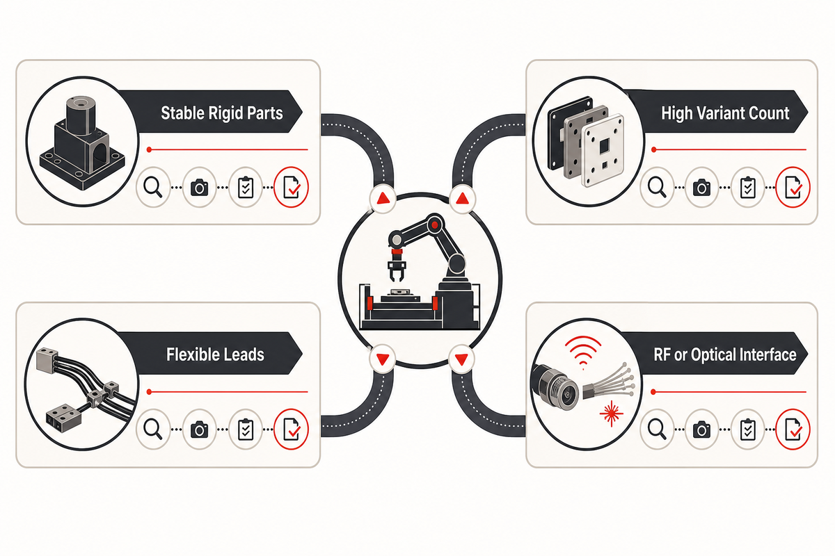
Dedicated equipment is plausible when parts can be presented repeatably, the assembly has accessible datums, connector variants share a manageable process, and the buyer can define what constitutes a conforming result. Connector labels alone—power, signal, RF, fiber, circular, rectangular, board-mount, or wire-to-board—don’t establish a common machine architecture.
Contact form changes the process. Loose stamped contacts, crimped leads, rigid pins, high-density multi-pin arrays, RF interfaces, and fiber-optic components may require different feeding, handling, cleanliness, force, and functional checks. Panel-mounted and PCB-mounted receptacles introduce comparable design splits. Classify the incoming state and required product evidence before choosing mechanisms.
Application examples include a plug-in module for wireless base station infrastructure equipment, a satellite communication chassis, and other serviceable communication equipment. Such examples describe where blind access can occur; they don’t establish compatibility. Review power contacts, signal contacts, the locking system, panel mounting, operating temperature, cable or board loads, and any multiple-connectors sequence for the actual design.
| Assembly condition | Machine implication | Evidence to request | Limitation |
|---|---|---|---|
| Stable rigid parts with clear datums | Conventional nests and controlled insertion may fit | Drawings, samples, datum study | Does not prove contact acceptance |
| Pre-terminated wires or flexible leads | Cable control and strain-free presentation matter | Wire range, dress, crimp condition | Free cable load can disturb alignment |
| High variant count | Recipe control and change parts may dominate | Variant matrix and forecast | One fixture may not cover all families |
| RF or optical interface | Cleanliness and functional verification expand scope | Interface-specific test requirement | Mechanical seating alone is insufficient |
| Uncontrolled incoming geometry | Inspection or supplier control is needed upstream | Capability data and defect samples | Automation cannot erase unstable inputs |
If the project doesn’t fit a narrow blind-mate assembly scope, the connector machine selector provides a broader route. End screening with a sample-trial question, not an assumption that one platform supports every connector series.
The Feed-Orient-Insert-Prove Chain
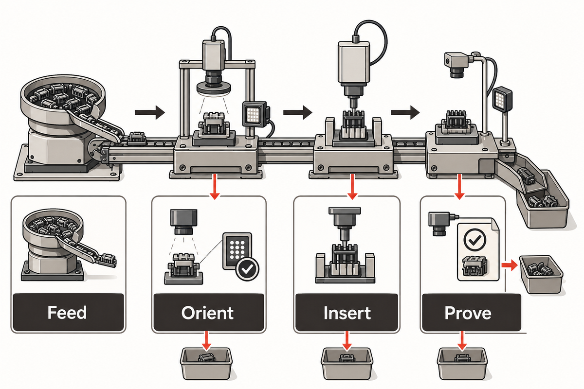
Defect prevention becomes manageable when each station has a named input condition, failure mode, detection method, reject path, and retained record. The 4-Stage Feed-Orient-Insert-Prove Chain keeps those decisions connected. Cycle-complete bits say the actuator finished its command; they don’t establish that the connector is conforming.
- Feed — supply, separate, and transfer parts while controlling shortage, doubles, contamination, deformation, and surface damage.
- Orient — verify identity, polarity, keying, contact direction, and correct recipe before insertion becomes possible.
- Insert — control datum location, approach path, force, depth, speed, interlocks, and abnormal-stop behavior.
- Prove — check required seating, presence, orientation, retention, electrical or optical characteristics, traceability, and physical reject separation.
NASA’s hosted copy of MIL-STD-1344A illustrates the distinction: connector assessment uses defined test methods and conditions for characteristics such as insertion and extraction forces, contact retention, continuity, and mechanical integrity. Production stations may collect useful process signals, but product acceptance must still point to the applicable requirement and method.
| Stage | Defect entering or created | Detection and reject action | Retained evidence | Limit |
|---|---|---|---|---|
| Feed | Missing, doubled, mixed, bent, or damaged part | Presence or vision check; stop or isolate | Feeder alarm, image, part identity | A sensor may not see hidden surface damage |
| Orient | Wrong key, polarity, direction, or recipe | Identity and feature check; prevent insertion | Recipe, inspection result, reject reason | Look-alike variants need controlled references |
| Insert | Off-axis entry, partial seat, damaged lock, abnormal load | Motion plus force/depth boundary; stop and quarantine | Trace, final position, stop code | Normal-looking force does not prove every feature |
| Prove | Missing seat, weak retention, open circuit, wrong reject route | Product-specific inspection and reject confirmation | Measurement, image, status, unit or lot ID | Test coverage is limited to specified characteristics |
A common error is adding a camera after the mechanisms are fixed, then discovering that the critical latch or terminal position is hidden. Put inspection access, lighting, gauge clearance, and bad-part removal into the concept layout. See connector inspection automation for the boundary of a separate inspection discussion.
Do
- Connect every known defect to a detection point
- Prove that rejects reach a controlled location
- Retain the evidence needed for diagnosis and release
Don’t
- Use actuator completion as product acceptance
- Assume one force limit finds every failure mode
- Let manual rework bypass identity and trace records
What Must the Machine Prove, Not Just Complete?
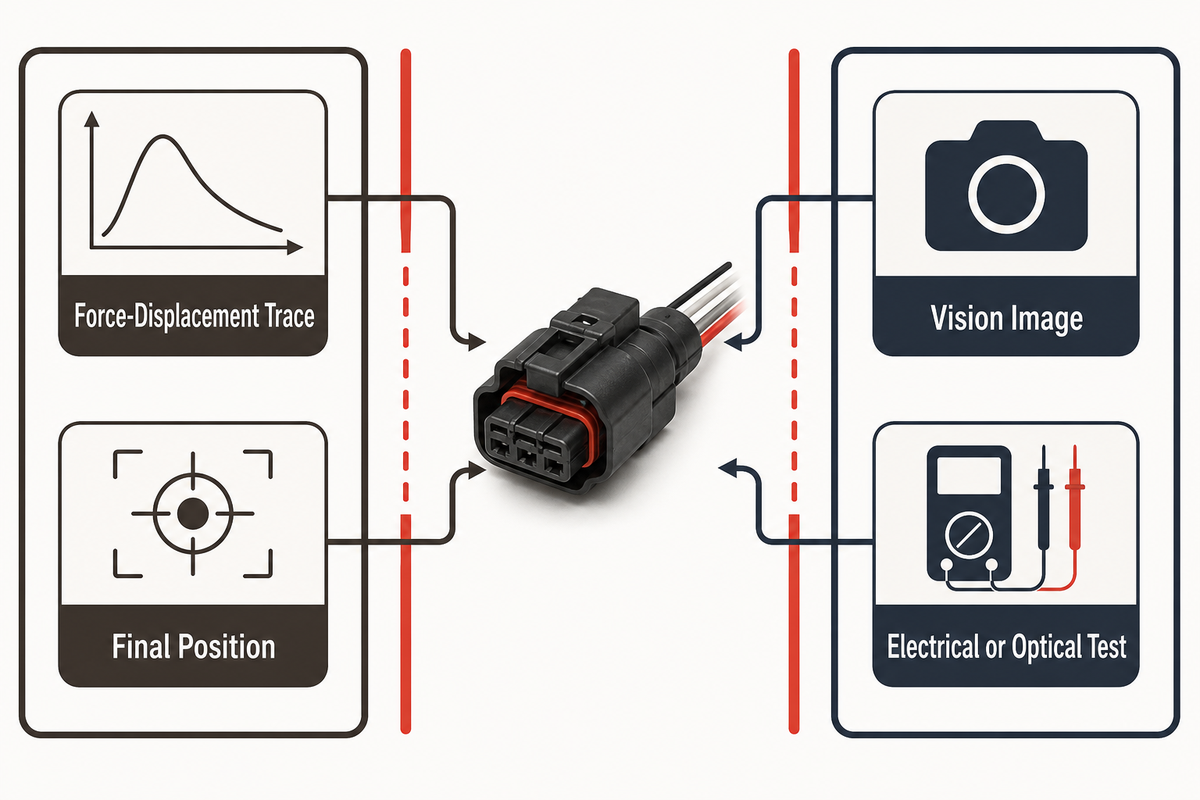
An acceptance plan must separate process evidence from product evidence. Force, motion, and station signals show what happened inside the machine. Seating, retention, electrical continuity, RF or optical performance, dimensional conformity, and damage checks establish selected characteristics of the product. Neither evidence class automatically replaces the other.
EIA-710, hosted by NASA, describes connector interface tests in a high-speed signal context and calls out controlled fixtures, test conditions, and reporting. For automation, scope discipline is the lesson: choose evidence that matches the connector’s real function. Force traces that catch a partial seat can be valuable without proving electrical, RF, optical, or retention performance.
| Evidence | What it can show | What it cannot prove alone | Acceptance owner |
|---|---|---|---|
| Force-displacement trace | Load changes along the insertion path | Electrical function, hidden damage, all retention features | Process engineering with quality approval |
| Final position or depth | Actuator or feature reached a defined location | Correct part identity or functional connection | Manufacturing and quality engineering |
| Vision image | Visible presence, orientation, or surface condition | Obscured features or electrical integrity | Quality engineering |
| Retention check | Resistance to the defined test load | Unmeasured circuits or unrelated dimensions | Product and quality engineering |
| Electrical or optical test | Named functional characteristics under test conditions | Every mechanical defect outside test coverage | Product and test engineering |
| Recipe, lot, and reject log | Which process and disposition applied | Conformity when measurements are missing | Quality and operations |
Measurement uncertainty also belongs in the decision. Limits can’t be judged responsibly if gauge resolution, calibration status, fixture repeatability, sampling location, or environmental condition makes the result ambiguous. Buyers should name which results release a part, which release a batch, and which are diagnostic only.
The Float-Force-Evidence Acceptance Protocol
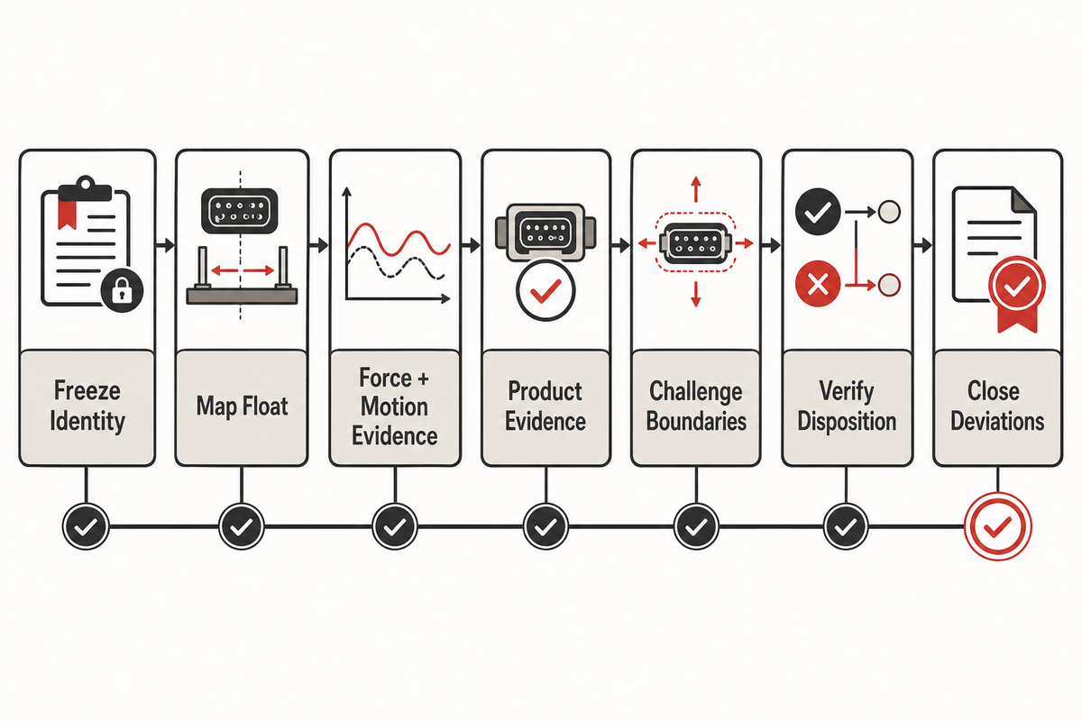
Sample runs become decision-grade when buyer and supplier agree on the input population, measurement boundaries, failure response, records, and sign-off before the first trial. The 7-Step Float-Force-Evidence Acceptance Protocol binds those choices together so a smooth demonstration with selected nominal parts can’t substitute for evidence across the approved project envelope.
- Freeze identity — record drawing, BOM, software, fixture, recipe, and test-method revisions.
- Map float — identify fixed and compliant datums, worst-case approach conditions, variants, and incoming-part limits.
- Define force and motion evidence — state the applicable trace, position, time, equipment, calibration, stop, and quarantine rules.
- Define product evidence — select seating, orientation, retention, electrical, optical, image, or dimensional checks that match the product requirement.
- Challenge the boundaries — run approved edge-condition parts and deliberate defect samples where safe, rather than nominal demonstration parts alone.
- Verify disposition — confirm pass routing, reject isolation, rework controls, retest rules, and record association.
- Close deviations — document failures, changes, repeated tests, residual risks, and accountable approval.
ISO 8092-2 covers definitions and general performance requirements for certain automotive on-board electrical connection systems, while the IEC and military connector documents above cover different domains and methods. That range is exactly why a sample protocol must name the governing specification. “Tested to a connector standard” is incomplete without the applicable document, edition, method, condition, and requirement.
Variable-based examples are safer than invented limits. Suppose a floating receptacle can move relative to a panel datum. Its trial pack would include the approved connector revision, nominal and agreed edge-condition assemblies, a controlled panel or carrier, a documented approach path, supplier-specified stop limits, a calibrated measurement chain, a product test, and recorded disposition. Passing means satisfying every pre-agreed field—not merely completing insertion.
Plant management may value stable output, finance may focus on capital exposure, and quality may insist on stronger test coverage. Pricing the same evidence package resolves that tension. Faster concepts that can’t distinguish a seated good part from a damaged or misrouted one move cost downstream instead of removing it. Procurement can then compare quotes by what’s proven, retained, and excluded.
Integration and Changeover Requirements
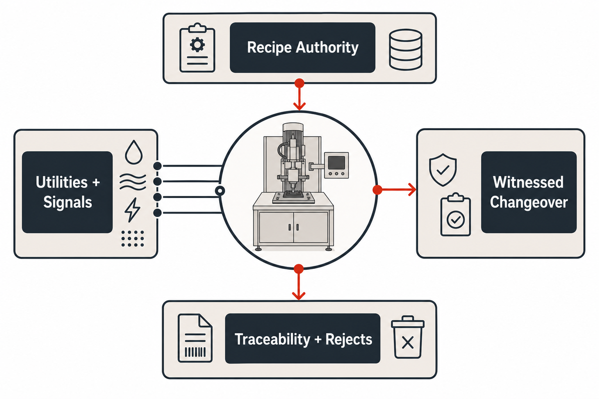
Insertion performance is only one acceptance boundary. Production-ready concepts must define upstream and downstream handoffs, utilities, footprint, guarding, operator access, maintenance access, part replenishment, recipe authority, line signals, traceability, reject removal, change parts, spares, and recovery after an interruption. Missing interfaces create disputes even when the insertion station works.
Dedicated tooling can suit stable geometry and sustained demand, but a new variant may require new nests, feed tracks, grippers, sensors, gauges, or software validation. Configurable tooling reduces some hardware changes while adding setup confirmation. Flexible cells can cover a wider mix only when handling, datum access, test scope, and changeover validation remain feasible. No architecture wins without the variant matrix and required evidence.
Write an interface-control sheet with each utility and signal, owner, physical boundary, normal state, fault state, recovery method, and acceptance check. Include upstream part identity, downstream unit identity, recipe download, result upload, reject-bin state, safety interlocks, and manual-recovery records. Approval of the plant-network may affect data design and schedule even though it doesn’t change connector mechanics.
See the connector assembly machines guide for broader architecture context. For this project, require a witnessed changeover that begins with the previous variant, follows the controlled instruction, confirms installed tooling and recipe, runs the agreed verification pieces, and records release approval.
When Not to Specify a Dedicated Machine
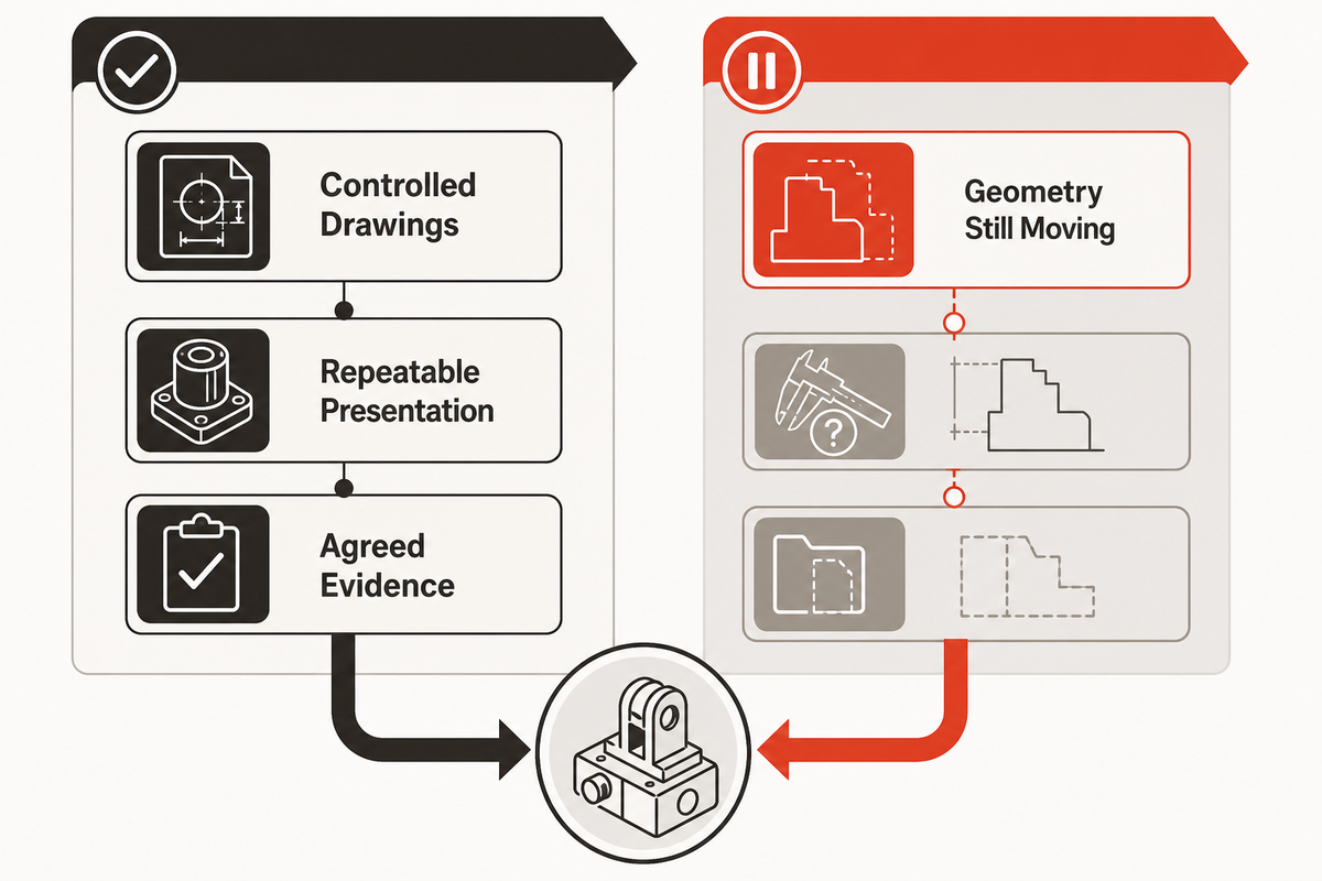
Pause a dedicated-machine purchase when product geometry is still moving, required tolerances are unknown, incoming parts can’t be presented consistently, variants defeat repeatable fixtures, inspection access is missing, or no one can state what evidence releases an assembly. Automation freezes assumptions; unstable assumptions return later as tooling changes, false rejects, escapes, and acceptance disputes.
Low or uncertain demand can justify guided manual tooling, a semi-automatic fixture, modular stations, or delayed automation. Compare manual and automatic options by their ability to control the named risks, collect required evidence, support variants, and change when the product matures. Design-for-assembly changes may be more valuable than asking a machine to compensate for a stack outside the connector envelope.
Proceed when
- Drawings, variants, and datums are controlled
- Parts can be presented and identified repeatably
- Required product and process evidence is agreed
- Worst-case samples can be built and tested
Pause when
- The product revision changes during quotation
- Connector float is expected to absorb an unknown system stack
- Cycle rate is specified but acceptance is not
- Reject and rework paths have no trace control
Build an Evidence-First RFQ
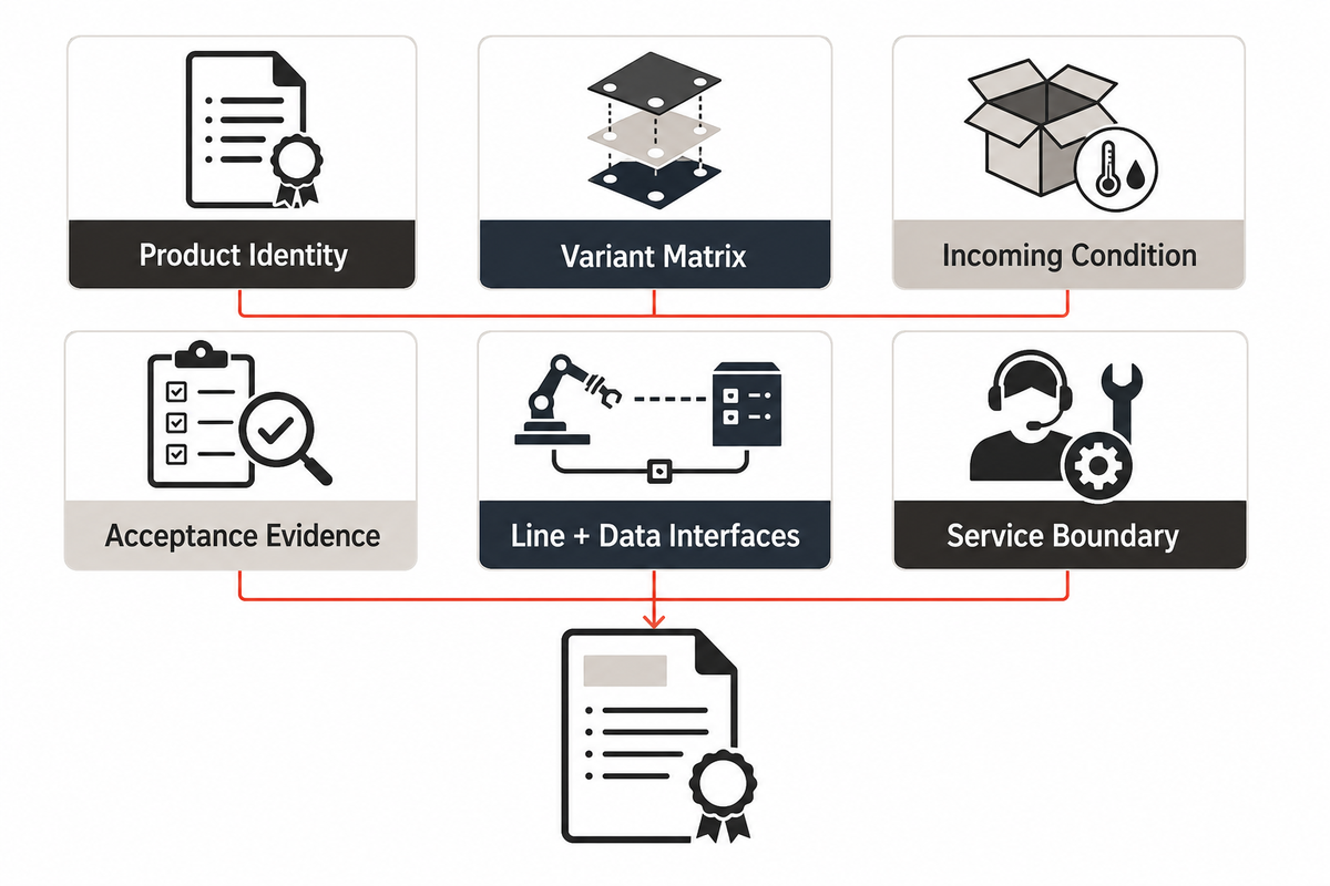
A comparable RFQ controls inputs, boundaries, and proof. Send current drawings, BOM and revision status, physical samples, a variant matrix, incoming-part conditions, demand and output assumptions, defect definitions, test requirements, line interfaces, traceability rules, changeover expectations, and the acceptance protocol. Ask every bidder to declare exclusions and evidence gaps.
Evidence-First RFQ — copy these fields into the quote request:
| Parameter | Project-specific value | Why it matters | How to verify |
|---|---|---|---|
| Product identity | Part numbers, drawings, BOM, and revisions | Prevents quotation against a stale configuration | Controlled document register |
| Variant matrix | Approved and future variants, shared features, differences | Controls tooling, recipe, and changeover scope | Supplier coverage response by variant |
| Incoming condition | Packaging, orientation, wire dress, cleanliness, allowed defects | Defines feed and inspection boundary | Samples from representative lots |
| Float and approach | Datums, offset, angle, guide sequence, final seat | Sets fixture and motion requirements | Float-to-Force Envelope and trial |
| Acceptance evidence | Process and product checks, methods, limits, records | Separates cycle completion from conformity | Witnessed protocol and report |
| Output basis | Mix, shifts, replenishment, test time, changeover assumptions | Makes capacity statements comparable | Timed run with stated exclusions |
| Line and data interfaces | Utilities, signals, safety, network, identifiers, retention | Prevents integration gaps | Interface-control test |
| Service boundary | Training, spares, change parts, documentation, response scope | Shows lifecycle responsibilities | Deliverable and acceptance register |
Quotation review should normalize each supplier response against this table. Mark “included,” “excluded,” “buyer supplied,” “subject to sample validation,” or “not yet proven” for every field. That approach helps a plant owner see schedule risk, lets quality find coverage gaps, and prevents procurement from comparing headline cycle rates built on different assumptions.
For a project ready to move from evidence planning to equipment discussion, review a blind mating connector assembly solution. Engineers from the ZEUEE automation engineering team can assess the supplied parts, drawings, variants, and acceptance boundary. Validation against the actual project remains required; the page isn’t evidence that any connector family will run without a sample review.
Discuss your connector assembly evidence pack
Frequently Asked Questions
What are some examples of blind mate connectors?
Examples include guided power and signal interfaces, floating board or panel connectors, circular and rectangular multi-pin interfaces, RF blind-mate connectors, and some optical interfaces. Those are process families, not one machine specification. Each project needs its actual guide geometry, contacts, mounting, cleanliness needs, cable or PCB loads, and acceptance tests reviewed before the assembly method is selected.
Where are blind mate connectors used?
Blind-mate interfaces are used where modules, racks, panels, or other assemblies must connect despite limited access or visibility. Application context changes the acceptance plan: power and signal connections, RF paths, optical paths, automotive environments, and serviceable modules can require different environmental, retention, continuity, cleanliness, traceability, and mating-life evidence. Connector and system specifications determine which tests apply.
What are blind mate RF connectors?
Blind mate RF connectors are radio-frequency interfaces designed to engage with limited direct guidance, often using lead-in geometry or compliant mounting to accommodate a specified mismatch. Mechanical seating doesn’t automatically establish a conforming RF path. Project teams must define the applicable frequency range, interface, mounting, alignment, cleanliness, insertion condition, and RF test evidence without borrowing limits from another series.
How is insertion force verified during a sample run?
Use a calibrated measurement chain, the approved fixture and motion profile, representative parts, and project-specific force-versus-position limits. Record the trace, stop result, part identity, equipment status, and final product checks; force alone doesn’t release the assembly.
What information should be sent with an RFQ?
Send controlled connector and contact drawings, BOM revisions, representative samples, a variant matrix, incoming packaging and part conditions, production mix, required output basis, known defects, inspection and functional tests, traceability needs, utilities, line interfaces, changeover expectations, safety and access constraints, service expectations, and a draft sample-run protocol. Identify which values are approved and which still require supplier testing. Ask bidders to mark every requirement as included, excluded, buyer supplied, or subject to a sample trial, then state the retained evidence for acceptance. Missing revision, datum, test, or acceptance information causes bidders to quote different problems, making price and delivery comparisons unreliable. Even a similar headline machine can hide different fixture, inspection, data, changeover, and service boundaries.
References & Sources
- IEC 60512-1: Connectors for electrical and electronic equipment — Tests and measurements
- MIL-STD-1344A: Test Methods for Electrical Connectors
- EIA-710: Electrical Performance Standards for High Speed and High Density Backplane Connectors
- ISO 8092-2: Road vehicles — Connections for on-board electrical wiring harnesses
- ngVLA blind mate connector alignment specification
Review note: Reviewed for engineering scope and source boundaries by the Shenzhen Zeyu Intelligent Industrial Science Technology Co., Ltd technical team. Final machine configuration and acceptance criteria remain application dependent.
WHY WE WRITE THIS
About ZEUEE Engineering Insights
ZEUEE shares technical guides based on real automation project experience. Since 2005, we have designed and manufactured non-standard automation equipment for connector assembly, wire harness production, robotic lines, vision inspection, and smart factory upgrades.
Founded in 2005
20,000 m² production base
120+ specialists
150+ R&D patents
ISO9001:2015 certified



![Automated Screwdriving: Torque & Cycle Time [Guide]](https://zeueeauto.com/wp-content/uploads/2026/10/automated-screwdriving-featured-150x150.png)


