Get in touch with Zeyu lntelligent Industrial Company

The Fiber Optic Connector Assembly Process, Station by Station

Updated August 2026 · Compiled from published standards and manufacturer process documentation
The fiber optic connector assembly process is the factory sequence that turns bare fiber and an empty connector body into a finished, loss-tested patchcord, and it runs indoors rather than on a ladder. Eight stations sit between a spool of fiber and a connector that ships: cable preparation, epoxy injection, cure, cleave, polish, end-face geometry, cleanliness inspection and loss acceptance. Each one has a number it has to hit.
Most writing on connector termination describes a different job: a technician cleaving and clamping a pre-polished fast connector in a splice enclosure. We audited page one for this exact query in August 2026: all six references behind Google’s AI Overview are field-installation walkthroughs, three of them YouTube videos, and not one of the five visible organic results follows the process into the factory. The closest, a connector-anatomy tutorial, stops at ferrule and body geometry. If you’re terminating in the field, the tooling guides serve you better than anything below. If you’re buying assembled connectors, specifying them, or building the line that makes them, these are the numbers your supplier is held to.
Quick Specs
| Share of connectors using heat-cured epoxy | About 95%, including factory-made patchcords |
|---|---|
| Typical oven cure | About 5 min at oven temperature; 65 °C for 15 min plus 15 min cooling in a lab procedure; overnight at room temperature |
| Polish ladder | 3 to 6 film stages, 30 µm down to 0.01 µm depending on ferrule material |
| End-face geometry envelope | Radius 7–25 mm UPC, 7–12 mm APC; apex offset under 50 µm; fiber height in the tens of nanometres |
| Loss acceptance | Grade B: mean 0.12 dB, maximum 0.25 dB for over 97% of samples |
| Cable-to-terminus pull-out floor | 98 N (22 lbf), held at least one minute |
The 8-Station Yield Ladder: what the fiber optic connector assembly process covers
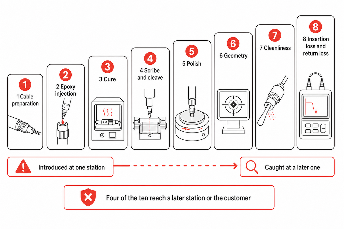
Factory connector assembly is the adhesive-and-polish sequence that bonds a bare fiber into a ferrule, removes the excess, shapes the end face to an optical geometry and proves the result by measurement. Field termination is a different job with different tools: a factory-polished fiber stub already sits inside the connector, and the technician’s task is to cleave and clamp against it.
That split isn’t a matter of opinion. Writing as a certifying body rather than a vendor, the Fiber Optic Association states in its guidance on adhesive and polish connectors that around 95% of all connectors, including every factory-made patchcord, use heat-cured epoxy. Meanwhile the practitioner consensus in field-installation communities is that nobody does epoxy and polish any more. Both statements are true of their own worlds, and the reconciliation is the point of this article: epoxy-and-polish didn’t disappear, it moved indoors.
That migration describes commercial volume production, not every context. MIL-STD-2042-5, Fiber Optic Cable Topology Installation Standard Methods for Naval Ships (Connectors and Interconnections), remains an active US Navy standard giving detailed methods for installing optical fiber cable connectors and interconnecting devices, with revision C published in 2016. Damaged runs at sea can’t be shipped back to a factory. Field termination isn’t obsolete; it’s a maintained military installation standard sitting alongside a commercial market that has largely centralised.
Keep the map below in mind for the rest of the article. Every defect this process can create is introduced at one station and caught at a later one, and the gap between those two columns is where scrap comes from.
| Station | Defect type it can introduce | Station that catches it | Measurement that catches it | Escapes to the customer if |
|---|---|---|---|---|
| 1 Cable preparation | Aramid not captured under the crimp | Nothing optical — only a pull test | Cable-to-terminus pull-out, 98 N held one minute | Retention is sampled rather than tested per piece |
| 1 Cable preparation | Buffer nicked during strip | Final loss test, sometimes months later | Insertion loss drift, mechanical failure under flex | The nick is shallow enough to survive final test |
| 2 Epoxy injection | Starved bore, no bead at the ferrule face | Polish, when the fiber pulls back | Fiber height goes negative; visual undercut | Geometry is not measured on every piece |
| 2 Epoxy injection | Air bubbles left in the bond line | Pull test or thermal cycling | Reduced pull-out strength | No environmental sampling is run on the batch |
| 3 Cure | Under-cured bead, still soft | Polish, immediately | Smearing, fiber pistoning, unstable geometry | Rarely — this one fails loudly at the next station |
| 4 Scribe and cleave | Crack propagating into the ferrule bore | Back-lit microscope inspection | Cracks visible only under rear illumination | Inspection is front-lit only |
| 5 Polish | Fiber undercut below the ferrule surface | Interferometer | Negative fiber height | Loss passes and geometry is skipped |
| 5 Polish | Altered surface layer raising reflection | Return loss test only | Return loss in dB — invisible to any microscope | Return loss is inferred from appearance |
| 6 Geometry | Apex offset outside the envelope | Interferometer, same station | Apex offset in µm against the connector family limit | Geometry is sampled by lot |
| 7 Cleanliness | Particles settling after final test | Nobody — the seal does not preserve it | Inspection at the point of mating, by the user | Always. This one is structural, not a process fault |
Compiled from the standards and process sources cited throughout this article; the acceptance measurements in columns four and five are the ones named in those documents.
Four of those ten defects reach a later station or the customer rather than the operator who made them. That distance is the argument for measuring, and it’s why the last three stations exist at all.
Station 1: cable preparation and the crimp that holds the fiber optic connector body
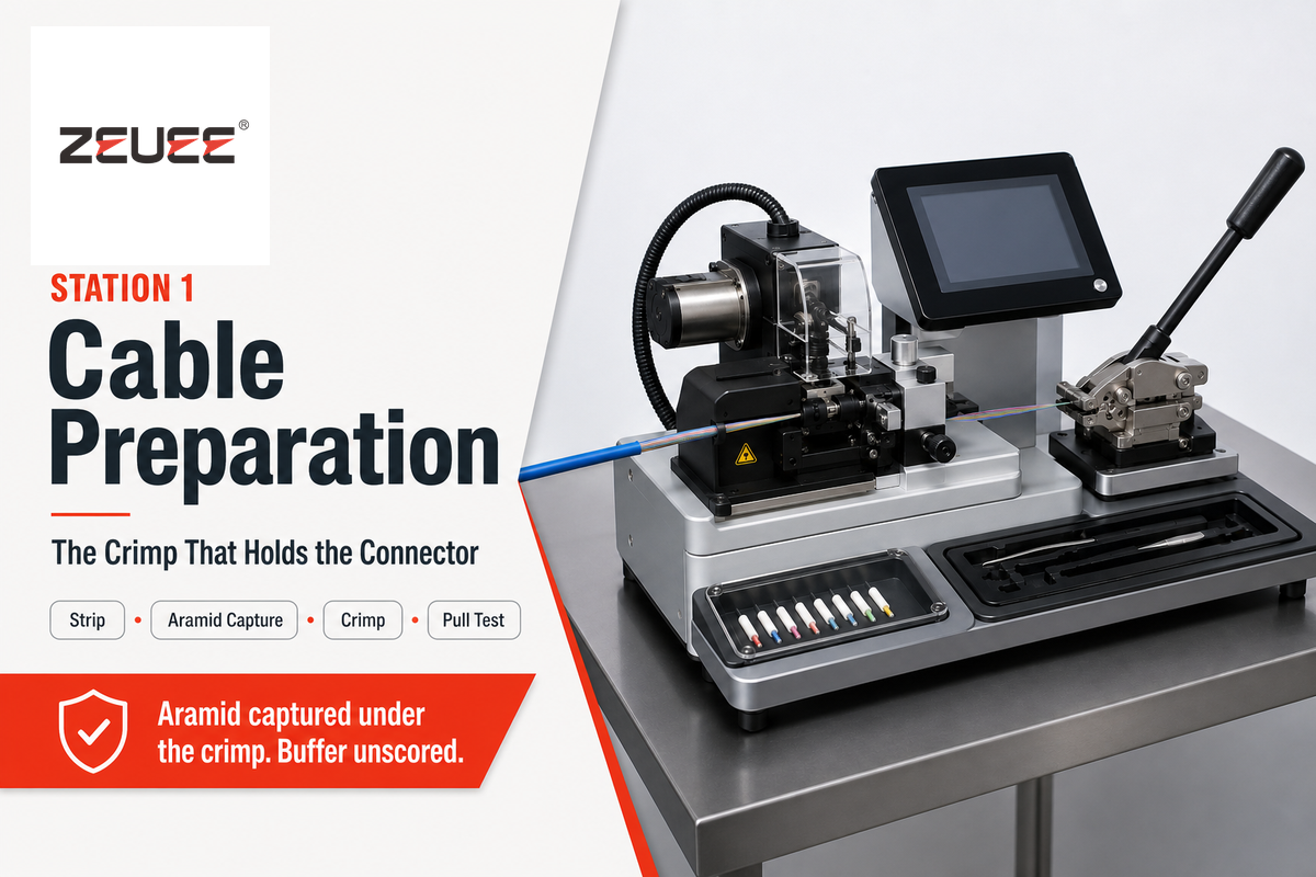
Cable preparation ends with two published pull-out limits, not one. MIL-PRF-29504C with Amendment 1, the US Defense Logistics Agency performance specification for fiber optic termini, sets a minimum fiber-to-terminus pull-out of 14 N (3.1 lbf) and a minimum cable-to-terminus pull-out of 98 N (22 lbf), each held for at least one minute.
Neither number is the crimp acceptance figure, and that’s the useful part. That specification carries two limits because the glass sitting in the terminus and the cable sitting in the strain relief are two different things being retained by two different mechanisms. Crimp sleeves that capture the jacket but miss the aramid strength member pass a casual tug and fail the 98 N test, because the load path runs through a plastic jacket instead of through the yarn engineered to carry it. Under the specification, a pass also requires no jacket damage, no crimp-sleeve failure, no terminus distortion and no cable disengagement, four separate observations, not a single go/no-go.
Incoming material has its own criterion. ITU-T L.101 (08/2024) gives a fiber proof-test strain equivalent to 1% as the normal reference value, with a different agreed or larger strain permitted for particular applications. Fiber that entered the building below that threshold doesn’t become acceptable because the connector on the end of it was assembled well.
Ferrule concentricity belongs to this station too, since it’s fixed before any adhesive is used: the eccentricity of the bore relative to the ferrule outside diameter sets a floor on mated-pair loss that no amount of polishing can lift.
Station 2: epoxy selection, dose and injection into the ferrule

Epoxy selection decides the shape of the whole line, because the adhesive brings two clocks with it and they run in opposite directions. Cure time sets how long a connector occupies the oven. Pot life sets how long a mixed batch stays usable, and therefore how many connectors one mix can serve before it’s thrown away.
Published ranges are wide. Room-temperature systems can carry a working life of about half an hour and cure overnight. Fast-curing systems reach polish-ready strength within an hour but give only five minutes of pot life, which caps the batch size hard. High-temperature systems, including the class rated for continuous service at 250 °C, can offer a four-hour working window and demand an oven in exchange. FOA guidance notes the shop-floor version of the same trade: an epoxy with a 30-minute working life lets an operator prepare a tray of connectors, and a 20-position oven curing in about five minutes then turns that tray over quickly.
Dose control is where the money is. One production manager at a German assembly house put the tolerance plainly: the dosing device is pre-adjusted to the specific fiber and connector combination, because every milligram counts.
“Every milligram counts.” Dosing devices are pre-adjusted to each specific fiber and connector combination rather than set once for the line.
Dr. Stefan Hanf, Production Manager, LASER COMPONENTS Germany GmbH
Two failure modes bracket the correct dose. Starved bores leave the fiber bonded over too short a length, and the fiber retracts under polishing pressure. Flooded connector bodies fill the cavity behind the ferrule with cured epoxy, which locks the strain relief solid and turns every cable flex into a stress concentration at one point. Separating them is a visual target published in the MIT OpenCourseWare 6.161 connectorisation procedure: inject from the back of the connector body until a bead appears on the outside face of the ferrule, and expel air from the syringe first, because bubbles left in cured epoxy weaken the bond. That same procedure checks the ferrule before use by looking through the bore at a light 30 to 45 cm away, and requires at least 2.5 mm of fiber to exit the ferrule tip on test fit.
Station 3: the cure schedule and the Cure-to-Cleave Window

If a line treats cure as a fixed dwell time, it has already lost the parameter that matters. There’s no such thing as the cure schedule. Published conditions for connector epoxies span five minutes in an oven to overnight on a bench, because cure belongs to the adhesive system rather than to the process, and any process sheet quoting a single universal figure is quoting its own supplier.
Call the interval between full cure and the scribe-and-cleave step the Cure-to-Cleave Window. It’s the span during which the bead has enough strength to hold the fiber against a cleave and a polish, but the line hasn’t yet paid for holding inventory in front of the polisher. Most process sheets leave it implicit, and it’s worth asking a supplier to name it, because two very different failures live on either side of it.
Cleave too early and the bead is still compliant. Fiber moves under the scribe, the stub breaks at an angle, and under polishing pressure the whole fiber pistons back into the bore, producing a negative fiber height that geometry inspection will reject at station six after every prior operation has been paid for.
Wait too long and nothing breaks, but the working assumption behind the schedule quietly stops holding. Faster is also not automatically better. Research published in the NTT Technical Review on field-assembly optical connectors makes the counter-intuitive case with a number: the gap between fiber and ferrule bore is under 1 µm, and across a bond line that thin an instant-setting cyanoacrylate gives a weak bond. Their primer is engineered to delay hardening, reaching polish-ready strength about five minutes after adhesion rather than instantly. That same paper puts a conventional heat cure at more than 30 minutes above 100 °C.
💡 Pro Tip
When you evaluate a supplier, ask for the pot life and the cure schedule as a pair. Five minutes of pot life with a one-hour cure, set against four hours of pot life with an oven cure, describe two completely different production lines, and only one of them can absorb an interruption without scrapping a mixed batch.
Station 4: scribe, cleave and the first inspection of the fiber ends
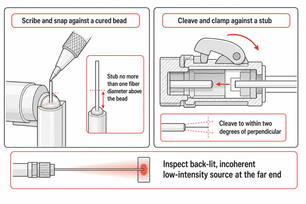
Scribe-and-cleave removes the excess fiber protruding above the cured bead, and it happens before any abrasive touches the part for a specific reason: a crack introduced here can propagate down into the ferrule bore, where no later polishing step will remove it and no front-lit microscope will show it. MIT’s procedure scribes just above the epoxy bead and leaves a stub extending no more than one fiber diameter above it, so the first polishing step removes material rather than a tall lever arm of glass.
Inspection at this point is where aerospace practice diverges usefully from commercial practice. NASA-STD-8739.5, Fiber Optic Terminations, Cable Assemblies, and Installation, requires fibers to be inspected back-lit, using an incoherent low-intensity source at the far end of the cable. Rear illumination reveals cracks that front illumination hides. That same standard names pistoning, axial movement of the fiber inside the ferrule, as an inspection item in its own right after retest, and treats end-face geometry and end-face quality as two separate compliance checks rather than one.
How the same step looks in a field termination
Field termination reaches the same place by a different route, and the contrast makes the factory constraints easier to see. A technician strips the plastic jacket from the fiber end, removes the coating from the fiber, and cleans the fiber with a lint-free wipe and alcohol.
Next, a technician will insert the fiber into the connector until the end of the fiber seats against the factory fiber stub within the ferrule, a cam or wedge holds the connector closed to secure the fiber in place, and a crimp sleeve is slid onto the connector over the cable entering the back. Boots go onto the fiber first, before any of this, and forgetting one is the reason so many otherwise good terminations are cut off and redone. Pre-polished connectors are used this way on both multimode and single-mode work. Manufacturers’ instructions typically call for cleaving the fiber to within two degrees of perpendicular, because a cleaved fiber end that isn’t square leaves a wedge-shaped air gap against the stub that index gel can’t fully compensate.
Adhesive termination replaces that seat with a bond. Rather than butting against a fiber stub installed at the factory, the fiber is inserted through epoxy and cured in place within the connector body, and the operator then has to gently scratch the excess fiber sticking above the bead with a carbide scribe and break off the fiber cleanly. Nobody uses a cleaver to cut the fiber at this point, because the stub is too short to hold. That single difference, scribe and snap against a cured bead, rather than cleave and clamp against a stub, is why mechanical fiber connectors can be installed by an occasional user and adhesive ones reward a daily one.
⚠️ Important
NASA-STD-8739.5 allows no rework path for a cracked flight assembly end face: the assembly is re-terminated or scrapped. It also carries across the requirement from NASA-STD-8739.6 that operators may not inspect their own work. Commercial lines are free to set a lower bar, but should set it deliberately rather than by omission.
Station 5: multi-stage polishing of the fiber optic connector end face

Polishing runs three to six film stages, and the step count is set by the ferrule material rather than by ambition. Published ladders range from a three-step 12 / 3 / 0.3 µm sequence to a five-step ceramic ladder that starts at 30 µm and finishes at 0.01 µm. No two published ladders match exactly, which tells you the step count isn’t the specification.
What’s stable is the logic. A coarse step removes the fiber stub and the epoxy bead. A shaping step establishes the curve. A scratch-removal step clears the damage the coarse step left. A final step exists for optical rather than geometric reasons, it addresses the altered surface layer that abrasive polishing leaves on the glass, whose changed refractive index raises reflection without changing anything a microscope can resolve.
Abrasive choice has to match the hardest material at the end face, and getting this wrong produces the failure most people assume is impossible. Writing in Cabling Installation & Maintenance, Mike A. Reed of Methode Electronics sets out the mechanism: overpolishing can be as damaging to a connector’s performance as underpolishing, because standard aluminium-oxide film removes glass and epoxy but not ceramic. Keep going after the ceramic has stopped cutting and the glass keeps receding, until the fiber sits undercut below the ferrule surface. Speckling in and around the core and cladding region is the symptom after a final 0.3 µm aluminium-oxide step. Recovery runs one micron diamond film on a resilient pad with distilled water, about ten figure-of-eight motions, because diamond cuts ceramic back to expose fresh glass and aluminium oxide can’t.
FOA guidance carries the same rule from the other direction, alumina for glass and epoxy, diamond when single-mode geometry is required, along with the pad specification that’s easy to miss on a process sheet: a 1/8-inch (3 mm) rubber pad at 80 durometer, and the instruction, in three words, not to over-polish.
📐 Engineering Note
Pad durometer and film grit are a matched pair, not independent settings. Softer pads let the film wrap the ferrule edge and round the radius of curvature down toward the bottom of the 7–25 mm envelope; a harder pad flattens it toward the top and drives apex offset up if the fixture isn’t square. If a line changes film supplier without re-qualifying the pad, expect the interferometer at station six to start rejecting parts that the loss test still passes.
Station 6: end-face geometry on the interferometer
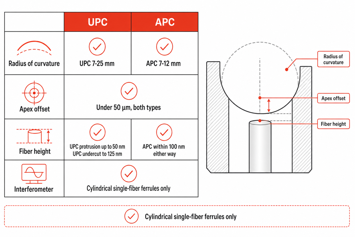
End-face geometry is graded on three numbers: radius of curvature, apex offset and fiber height. Radius of curvature is the radius of a sphere fitted to an annulus around the fiber, not to the whole face. Apex offset is the lateral distance from that sphere’s vertex to the fiber centre. Fiber height is the fiber’s position relative to the surrounding ferrule surface, positive when it protrudes and negative when it’s recessed.
Those three numbers describe cylindrical single-fiber ferrules, PC, UPC and APC. They aren’t a general model of connector geometry, and the matrix below carries that scope in its caption for a reason given immediately after it.
| Parameter | UPC | APC | Instrument | What fails when it drifts |
|---|---|---|---|---|
| Radius of curvature | 7–25 mm | 7–12 mm | Interferometer | Physical contact is lost at the core; insertion loss rises |
| Sphere fitting area | Annulus, 250 µm outer / 140 µm inner | Same annulus convention | Interferometer software | Two labs report different radii for one part |
| Apex offset | Under 50 µm | Under 50 µm | Interferometer | Contact point moves off the core; loss and reflectance both worsen |
| Fiber height, protrusion | Up to +50 nm | Within ±100 nm | Interferometer | Fiber damage on repeated mating |
| Fiber height, undercut | To −125 nm | Within ±100 nm | Interferometer | Air gap at the interface; return loss collapses |
| End-face angle | Nominally flat | 8 degrees nominal | Interferometer | Angle mismatch on mating; large loss penalty |
| Key-to-angle alignment | Not applicable | Required | Fixture and interferometer together | A correct angle in the wrong rotational position still fails |
| Surface quality after final step | No core scratches | No core scratches | Fiber inspection microscope | Insertion loss rises; return loss may not move at all |
| Governing documents | IEC 61755 series for the interface; Telcordia GR-326-CORE for qualification | Same, with the angled-ferrule part | IEC 61300 series for the measurement method | Citing “the IEC standard” without the series number cites nothing |
Limit values as published by Hexatronic Data Center attributing Telcordia GR-326-CORE. Vendor restatements of this envelope differ at the band edges, other suppliers publish 10–25 mm for UPC and 5–12 mm for APC, which is itself the reason to ask which document a quoted limit came from. That dimensional interface is defined in IEC 61755-3-1:2024 for straight zirconia ferrules and IEC 61755-3-2:2024 for angled ones, both behind a paywall; the measurement method sits in the IEC 61300 series. If a supplier quotes you an envelope, ask which of those two documents it comes from.
Rectangular multifiber ferrules get handed to their own standard rather than swept under those three numbers. IEC 61300-3-30:2026, edition 3.0, published on 27 July 2026, measures rectangular multifiber ferrule geometry by four different attributes: fiber position relative to the endface, endface angle relative to the guide holes, fiber tip radii, and core dip for multimode fibers. Only tip radius even rhymes with the single-fiber set, and an angle measured relative to the guide holes has no single-fiber equivalent at all, because a single-fiber ferrule has no guide holes. Edition 3 adds geometry limit tables for 16-, 24- and 32-fiber ferrules, which is a direct read on where multi-fiber connector density is heading.
Station 7: end-face cleanliness inspection before the connector ships
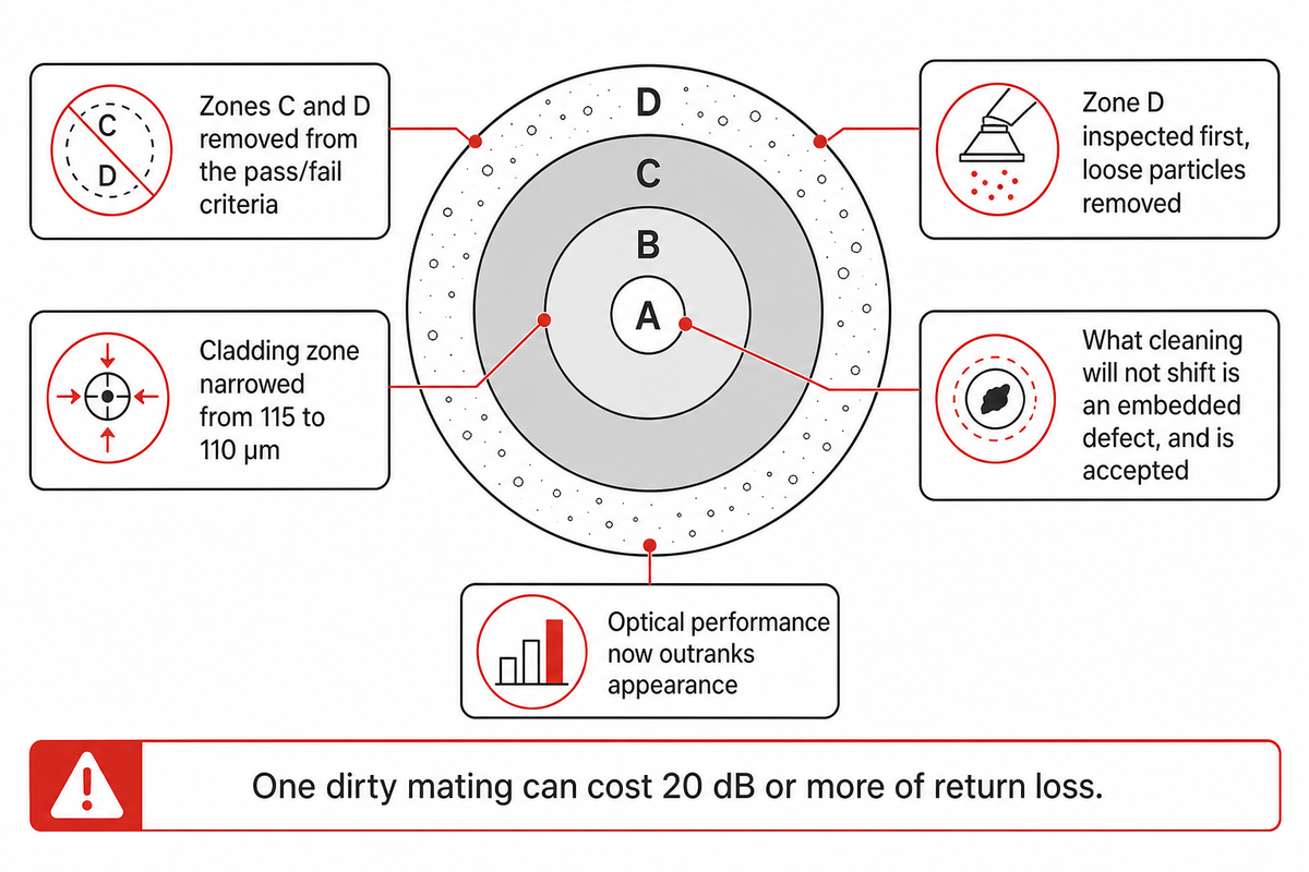
For end-face cleanliness, the standard changed its mind in 2022 and most of the industry has not caught up. IEC 61300-3-35:2022, the end-face visual inspection method within the IEC 61300 examinations-and-measurements series, removes zones C (adhesive) and D (contact) from the pass/fail criteria entirely at edition 3. Zone D is now inspected first, loose particles are removed, and anything that repeated cleaning will not shift is deemed an embedded defect and accepted.
Further down sits the consequential change. Edition 3 adds a statement that a connector can’t be rejected on a failed visual inspection alone: meeting the specified optical performance is what determines whether it gets used, so a face that has been cleaned of loose debris and still looks wrong can ship if insertion loss and return loss testing pass. Optical performance now outranks appearance. Every supplier page describing end-face inspection as a pass/fail gate on how the face looks is describing edition 2 practice. Zone A and Zone B criteria were also relaxed slightly and defined better, and the cladding zone itself narrowed from 115 to 110 µm, because contamination at the very edge of the cladding doesn’t meaningfully attenuate anything. For rectangular arrays, the whole ferrule is inspected and cleaned before Zone A and Zone B are assessed per fiber.
Contamination deserves the attention it gets. Fluke Networks’ analysis of return loss causes ranks dirty end faces first by a wide margin, with a single dirty mating capable of degrading return loss by 20 dB or more. Twenty decibels is the distance between a 45 dB connector and one worse than 26 dB, three grades, from one mating.
One honest caveat belongs here, and it’s the part that a factory can’t fix. FOA advice is to inspect and clean brand-new patch cords out of their sealed bags before use. Factories guarantee the end face at the moment of final test; the bag doesn’t preserve that state. Cleaning wants 99% isopropyl alcohol rather than the 70% sold as rubbing alcohol, because the balance in the cheaper grade is water, and water leaves residue on a face you’re about to mate.
Station 8: insertion loss and return loss acceptance
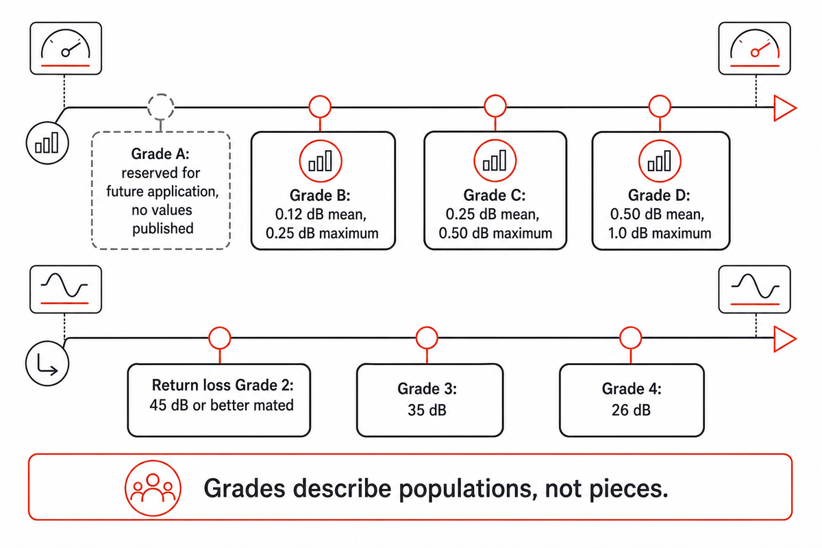
Connector loss acceptance is a pair of numbers with a population qualifier attached, and the single figure quoted on most supplier pages is neither of them. Under the attenuation grades defined in IEC 61755-1 and tabulated in IEC 61755-2-1:2022, a Grade B connector means a mean attenuation of 0.12 dB or less and a maximum of 0.25 dB or less for over 97% of samples. Grade C is 0.25 dB mean and 0.50 dB maximum; Grade D is 0.50 dB and 1.0 dB. Grade A sits in that table with no values against it, reserved for future application, so B is the best attenuation grade a fiber optic connector can be built to today. Return loss grades run separately and, Grade 1 aside, describe non-angled contacting fibers: Grade 2 at 45 dB or better mated, Grade 3 at 35 dB, Grade 4 at 26 dB. Grade 1, at 60 dB or better, is reserved for angled physically contacting fibers under IEC 61755-2-2.
Grades describe populations, not pieces. EN IEC 61755-1:2022 sets those grades inside a random-mating population framework. Attenuation is measured by IEC 61300-3-34 for single-fiber connectors and IEC 61300-3-45 for multi-fiber ones, return loss by IEC 61300-3-6, and the grades hold from 1310 nm to 1625 nm. IEC 61753-1 is the performance standard the finished product is qualified against, which is a different question again from what one piece reads on one bench. What the standard supports is “this line produces Grade B connectors,” not “this connector is Grade B” — and conflating the per-unit figure with the certified population grade is the most common specification error in this market.
Here is the arithmetic on a real span, using a light source and power meter at 1310 nm. Take a 4 km single-mode run with four mated pairs and two fusion splices. Fiber attenuation at 0.35 dB/km over 4 km gives 1.40 dB. Four mated pairs at the FOA’s link-budget allowance of 0.3 dB each give 1.20 dB. Two splices at 0.1 dB give 0.20 dB. Total: 2.80 dB. Against a fiber optic transmitter and receiver pair with a 5 dB power budget, the margin is 2.20 dB. Now swap the connector allowance for the ANSI/TIA-568 maximum of 0.75 dB per connection and the four pairs cost 3.00 dB, the link totals 4.60 dB, and the margin falls to 0.40 dB. FOA guidance is blunt about which figure describes reality: 0.75 dB is not a good connector, and current field-terminated multimode connectors should be under 0.3 dB, with factory single-mode connectors in the 0.1 to 0.2 dB range.
What the eight stations do not test
Everything above measures the process. Qualification of the product happens in a separate regime, run on samples rather than on every piece, and buyers are almost never shown it. IEC 61753-022-02:2026, a first edition superseding the 2012 document, covers multimode connectors terminated as pigtails and patchcords for category C, controlled environment.
Its changes against the previous edition are the dimensioned material worth quoting: a torsion test added; fiber and cable retention on reinforced cables cut from 120 s to 60 s minimum; the static side load test deleted; strain-relief flexing now judged on change in attenuation instead of transient loss; mating durability for cylindrical ferrule connectors cut from 500 cycles to 200; mating durability for rectangular ferrule connectors added at 50 cycles; and a new Annex B on visual examination of outer cable sheath movement during the temperature-change, cable-retention and strain-relief tests.
Purchasers comparing suppliers on end-face photographs and a loss report are comparing process outputs. Asking which performance standard and which category the assembly was qualified against is a different question, and a cheap one to ask.
Epoxy-and-polish against splice-on, mechanical and pre-terminated connectors
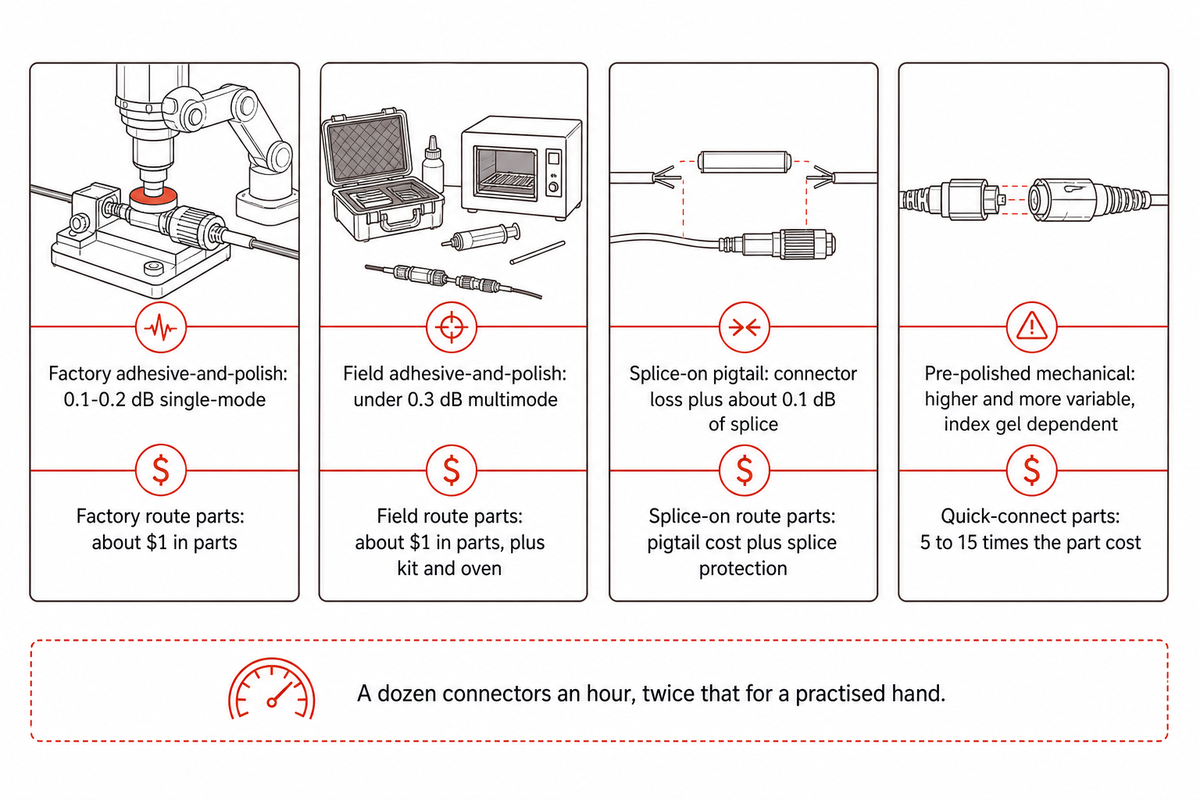
Fusion splicing onto a factory pigtail beats epoxy-and-polish for anyone terminating fewer than a few hundred connections a year, because the loss performance is comparable and the skill is bought once in the splicer rather than acquired over months at a polishing puck. Volume is what flips the comparison, and the flip point isn’t subtle.
| Route | Typical loss | Consumable cost per connector | Skill dependence | Rework path | Not suitable for |
|---|---|---|---|---|---|
| Factory adhesive-and-polish | 0.1–0.2 dB single-mode | About $1 in parts | Low per operator, high per process | Re-polish, including diamond recovery of an undercut face | One-off repairs; anything needing a connector in the next hour |
| Field adhesive-and-polish | Under 0.3 dB multimode when done well | About $1 in parts, plus kit and oven | High — a dozen connectors an hour, twice that for a practised hand | Re-polish on site if a puck and films are present | Occasional users; jobs with no power for a curing oven |
| Splice-on / pigtail plus fusion splice | Factory connector loss plus about 0.1 dB of splice | Pigtail cost plus splice protection | Moderate; the splicer carries the precision | Cut back and re-splice | Sites with no splicer access; very tight enclosure space |
| Pre-polished mechanical (quick-connect) | Higher and more variable; index gel dependent | 5 to 15 times the adhesive-and-polish part cost | Low — the factory did the polish | Usually discard and fit another | High-count terminations where part cost dominates; long-life single-mode links |
Loss and cost figures from the Fiber Optic Association’s adhesive-and-polish guidance; splice loss from the worked budget above. Connector styles and their identification are covered in the FOA’s connector identification reference.
When epoxy-and-polish is the wrong route
The economics only work above a threshold, and the FOA’s own time-and-motion observation sets it: the connector is the cheap part at roughly a dollar, but a practised operator produces about a dozen an hour, or twice that with real speed. Below a few hundred terminations, the labour and the learning curve swamp the parts saving, and the honest recommendation is a pigtail and a splicer.
Choose adhesive-and-polish when
- Volume runs to thousands of terminations and part cost dominates
- Single-mode geometry has to be held inside a 7–25 mm radius envelope
- A curing oven, an interferometer and a loss bench are all available in one place
- The same operators run the process daily rather than occasionally
Choose another route when
- Fewer than a few hundred terminations a year are needed
- The work happens in an enclosure with no power and no bench
- Nobody on site polishes regularly enough to stay in practice
- A single repair is needed today rather than a batch next week
Reference-grade test cords are worth calling out as a separate case. Practitioners treat them as consumables with a working life in the low hundreds of mating cycles, against the far higher counts quoted for production connectors, precisely because their end faces are the reference the rest of the measurement rests on.
Connector types, adapters and the special tools each installation method needs
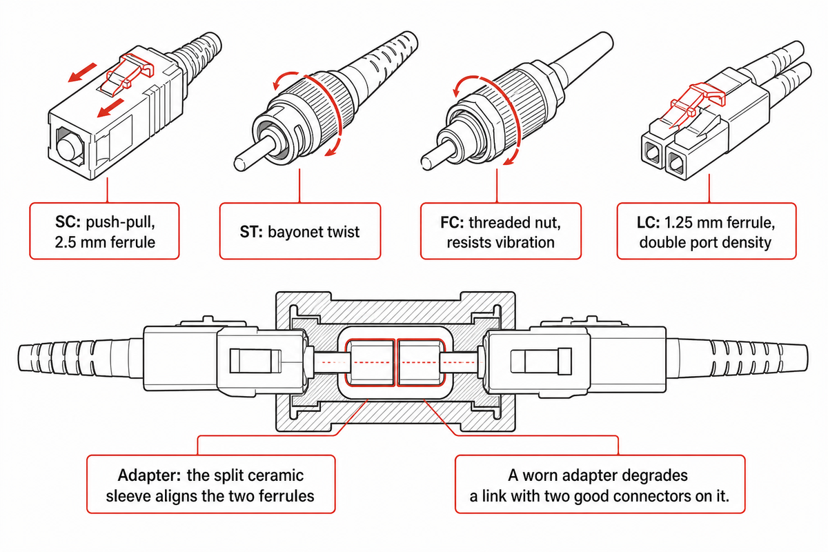
Four form factors cover most of what ships today. SC, ST and FC connectors are built on a 2.5 mm ferrule and differ only in how they latch; LC halves that to a 1.25 mm ferrule to double port density. The FOA’s connector identification reference is the practical way to tell them apart in the field.
Latching is what separates them, and connectors are generally chosen on that mechanism rather than on optical performance, since a technician has to easily connect and disconnect them a thousand times over the life of a patch field. An SC connector pushes and pulls straight in and out, which makes it easy to install where a hand can’t get around the body. An ST connector uses a bayonet twist, an FC connector a threaded nut that resists vibration, and an LC connector a small plastic latch like an RJ45 tab. Because the ferrule diameter is shared, ST or SC parts interchange across a bulkhead far more readily than either does with LC, and SC and LC connectors together account for the overwhelming majority of current structured cabling.
Adapters are the other half of the interface and get less attention than they deserve. An adapter is a sleeve that holds two connectors nose to nose, and the split ceramic sleeve inside it is what actually aligns the two ferrules. Both adapters and connectors are available in simplex, duplex and quad bodies, and hybrid adapters are used to connect one connector type to another. Because a connector ferrule only ever touches its partner inside that sleeve, a worn adapter degrades a link that has two perfectly good connectors at both ends.
Tooling divides on the same line the whole article does. Factory work needs a curing oven, polishing fixtures, an interferometer and a loss bench. Field work needs a different set of special tools: fiber strippers sized to remove the coating from the fiber without scoring the glass, an inspection scope for checking a fiber end or connector before it’s mated, and a cleaning kit. Crews who splice rather than polish also use a fiber optic cleaver accurate enough to square the end. Strippers one size out will nick the cladding, and a fiber cleaver that has walked off its blade index will produce an angled end no amount of care downstream will fix.
Fiber pigtails sidestep most of that. Pigtails are short single fiber leads carrying a factory connector on one end and bare fiber on the other, spliced into the cable in a fiber terminal box or tray. Because the connector was made and measured indoors, the installation method reduces to one fusion splice, which is why professional fiber crews reach for pigtails on multimode fiber and single-mode work alike. That same logic scales up: aerial fiber routes and access networks carrying broadband and cable television traffic are increasingly built from preterminated assemblies rather than terminated on site.
Whoever will install fiber optic hardware on site should be named before the type of connectors is fixed, because a successful fiber connector installation depends more on who does it than on which brand is bought. Fiber optic connector installation by an occasional user argues for a pre-polished type; daily work argues for adhesive and polish.
Choosing a type of fiber and choosing a connector aren’t independent decisions. Multi-mode fiber tolerates more lateral misalignment than single-mode, so the different types of fiber optic connectors carry different geometry budgets even when the ferrule looks identical. Correct installation of a fiber optic link starts at the specification, not at the crimp: an optical fiber chosen for one loss budget and a connector graded for another will meet in the middle at the first test.
Where termination demand is moving, and what it changes on the floor
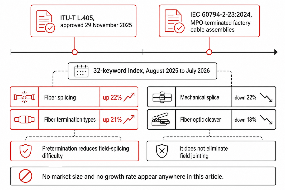
Two standards bodies published documents on factory-terminated assemblies within twenty-two months of each other, which is the clearest available signal about where this work is going. ITU-T L.405, approved on 29 November 2025, defines preconnectorized housings, closures, cable assemblies and terminals as components factory-terminated with connectors. IEC 60794-2-23:2024, a first edition published on 31 January 2024, specifies indoor multi-fiber cable written specifically for MPO-terminated factory cable assemblies.
Our own demand measurement points the same way without claiming to be a market statistic. Across a 32-keyword index tracked over the twelve months from August 2025 to July 2026, searches for fiber splicing rose 22% and for fiber termination types 21%, while mechanical splice fell 22% and fiber optic cleaver fell 13%. Buyer vocabulary is shifting toward fusion-based routes and away from mechanical ones, which pushes volume termination further into the factory rather than the field.
That claim is bounded, and the bound comes from the same standards body. ITU-T L.250 (01/2024) describes pre-terminated assemblies as optional and deployed optical plant as a mixture of aerial, underground, duct and microduct technologies. Pretermination reduces field-splicing difficulty; it doesn’t eliminate field jointing. So the honest statement is about where the specification work is going, not about a volume split between factory and field.
No market size and no growth rate appear anywhere in this article. Six syndicated market-research pages on this exact topic were checked during research. For the same year they put the market anywhere between 5.61 and 11.2 billion dollars, with growth rates from 4.1% to 12.6% — a factor of two on the size and a factor of three on the growth. Those numbers are printed here only as evidence of the disagreement, which is what makes every one of them unquotable.
For a buyer, the practical consequence is a specification question rather than a forecast. If your supplier is quoting MPO assemblies, ask whether the cable itself is specified to IEC 60794-2-23:2024 and whether the geometry is measured against the 2026 edition of the rectangular-ferrule standard, because both documents are new enough that a supplier may still be working to their predecessors.
What changes when the connector assembly process is automated
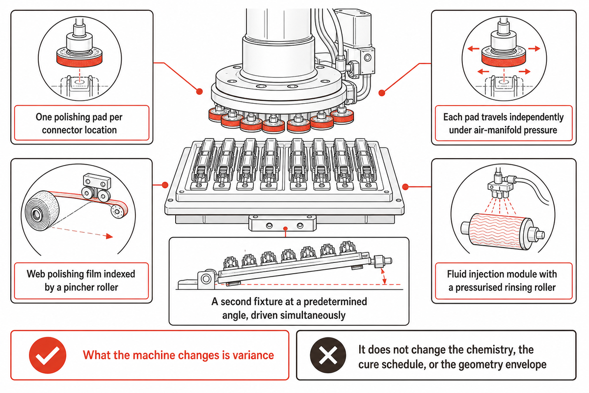
Automation on this line doesn’t buy faster hands. It holds constant what a hand can’t hold constant, and the mechanisms are specific enough to check against a patent. EP1597021A1, Apparatus and method for polishing a fiber optic connector (ADC Telecommunications, filed 26 January 2004, published 23 November 2005), describes four of them.
First, one polishing pad per connector location, each travelling independently in the vertical direction under air-manifold pressure so that every pad engages its end face at equal force regardless of that face’s position. On a hand puck a connector sitting slightly proud takes more pressure than its neighbour, and that difference is the fiber-height spread station six rejects.
Second, a web polishing film indexed by a pincher roller. Abrasive state is advanced by the machine rather than worn to an unknown condition by an operator who can’t see it degrading. That patent’s worked example names one micron diamond lapping film, the same one-micron diamond specified for single-mode work and prescribed for recovering an overpolished ferrule.
Third, a fluid injection module with a pressurised, fluid-saturated rinsing roller that clears debris in line, before the next stage drags it across the face.
Fourth, a second fixture held at a predetermined angle and driven simultaneously with the first, so angled and flat physical contact finishes run in parallel on one machine instead of requiring a changeover.
Loading is a purchasing decision rather than a property of the process: the same patent specifies that fixtures may be loaded “manually, such as by hand-feeding the fixtures into the machine, or automatically, such as by a conveyor system.” Lines can automate the polish and keep manual loading, or automate both. What the machine changes is variance: dose repeatability, pressure per location and film condition all stop depending on which operator is on shift. What it doesn’t change is the adhesive chemistry, the cure schedule, or the geometry envelope the end face must land inside.
Equipment built for this work sits in the same family as our automated fiber optic connector assembly machine line, alongside the optical connector assembly line for higher-volume builds. Measurement is a separate purchase: end-face and geometry checking belongs with connector inspection automation, and the camera work behind it with vision inspection systems. Readers scoping a whole cell rather than one station will find the broader treatment in our guide to connector assembly machines and, for the plant-level view, production line automation. Precision-electronics buyers can see the sector context on our 3C electronics industry page.
The one thing to carry awayEvery station in this process introduces a defect that a later station has to catch, and the four that escape their own operator are the reason acceptance is a measurement rather than an inspection. Ask a supplier which stations measure every piece and which sample by lot — that single answer tells you more about the connectors you will receive than any end-face photograph.
Discuss a connector assembly line with our engineers →
Frequently asked questions
Q: How are fiber optic cables typically joined together?
Fiber optic cables are joined either by fusion splicing, which fuses two fibers into one continuous path, or by connectors, which allow the joint to be opened again.
Fusion splicing gives the lowest loss and creates a permanent joint, typically around 0.1 dB. Connectors cost more loss but can be disconnected, which is why every patch panel uses them. Mechanical splices sit between the two: an alignment sleeve with index-matching gel, no fusion, higher and more variable loss. Which one belongs on a job is set by whether the joint ever needs to open again.
Q: What is the most common mistake people make when implementing fiber optics?
Treating end-face contamination as a housekeeping issue rather than a measured parameter is the most common and most expensive mistake in fiber optic work, because a single dirty mating can cost 20 dB or more.
Dirty end faces are the leading cause of return loss failure, and that 20 dB penalty is enough to move a connector three performance grades. Worse, mating a contaminated connector embeds the debris, and once embedded, cleaning leaves pits behind permanently. Brand-new patch cords straight out of a sealed bag are not exempt: the factory guaranteed the face at final test, and the bag does not preserve it. Inspect before every mating, and clean with 99% isopropyl alcohol rather than 70% rubbing alcohol.
Q: How difficult is it to splice fiber?
Fusion splicing is easier to learn than adhesive-and-polish termination because the splicer carries the precision, but the equipment cost is front-loaded, and that capital outlay is what actually decides the choice for most installers.
Modern fusion splicers align, fuse and estimate loss largely on their own, so the skill sits mostly in preparation: a clean strip, a good cleave, and correct fiber handling. That is why field practitioners overwhelmingly recommend a pigtail and a splice over field polishing. The trade is capital, not difficulty.
Q: What do OS1, OS2, OM1, OM2, OM3 and OM4 mean?
OS1 and OS2 are single-mode fiber classifications; OM1 through OM4 are multimode fiber classifications graded by modal bandwidth, and the pair of letters on a spec sheet is what tells you which alignment budget the connector has to hold.
OS1 designates single-mode fiber intended for tight-buffered indoor cable, OS2 for loose-tube outdoor and long-haul construction with lower attenuation. Both carry a 9 µm core.
The OM series covers multimode fiber with a 62.5 µm core in OM1 and 50 µm in OM2 through OM4, with each step up carrying more modal bandwidth and therefore more distance at a given data rate. OM3 and OM4 are laser-optimised for use with VCSEL sources.
Core diameter sets how much lateral misalignment the interface absorbs, so single-mode work tolerates far less ferrule eccentricity and apex offset than multimode work, and the acceptance target moves with it: under 0.3 dB for field-terminated multimode against 0.1 to 0.2 dB for factory single-mode. Connector specifications without the fiber type attached are incomplete.
Q: How do I connect a fiber optic cable to a connector?
Strip the jacket and buffer, thread the cable into the connector body, crimp the strength member, then either cleave against a factory stub or bond and polish.
Which of the last two applies depends entirely on the connector type you bought. Pre-polished mechanical connectors end at the cleave and clamp. An adhesive-and-polish connector continues into the eight stations described above.
Q: Does it make sense to put LC connectors on a fiber yourself?
For a small number of terminations, buying a factory patchcord or splicing a pigtail almost always beats fitting LC connectors yourself, because the hourly rate of a practised hand and the kit needed to prove the result both work against a small job.
The consumables argument misleads. The connector costs about a dollar in parts, but the working rate is roughly a dozen an hour for someone who does it regularly, and a polishing kit, curing oven, inspection microscope and loss set are all needed before the first one is any good.
Field technicians consistently advise a pre-polished mechanical connector on site, or a pigtail fusion-spliced in. Epoxy-and-polish isn’t hard in principle; it needs a controlled cure, a matched pad and film ladder, and instruments to prove the result, precisely what moved this work into factories.
Related Articles
- Automated assembly machines guide how multi-station special-purpose machines are scoped and configured
- Production line automation guide conveyors, handling and data logging across a whole assembly cell
- Automated testing equipment guide building the measurement stations that make acceptance criteria enforceable
- Connector contact types guide how contact geometry differs across connector families
About This Analysis
ZEUEE builds non-standard automation equipment, including fiber optic connector assembly and optical connector assembly lines, from a 20,000 m² manufacturing base in Taihe, Jiangxi. The company states that it was founded in 2005, holds ISO9001:2015 certification, and has filed more than 150 research and development patents, at least 32 of them invention patents. Station sequence, cure and polish parameters and acceptance limits above were assembled from published standards and process documents rather than from any single supplier’s process sheet, and every geometry, loss and retention figure is attributed to the document it came from. Where a number couldn’t be sourced, as with production yield, rework rates and connector market size, none is quoted.
References & Sources
- NASA-STD-8739.5, Fiber Optic Terminations, Cable Assemblies, and Installation NASA Technical Standards System
- 6.161 Modern Optics Project Laboratory, Lab 7 connectorisation procedure MIT OpenCourseWare
- Hints for Adhesive/Polish Fiber Optic Connectors The Fiber Optic Association
- Fiber optic connector identification reference The Fiber Optic Association
- IEC 61300-3-35:2022, visual inspection of fibre optic connectors and fibre-stub transmission components International Electrotechnical Commission
- IEC 61300-3-30:2026, endface geometry of rectangular ferrule multifibre connectors International Electrotechnical Commission
- EN IEC 61755-1:2022, connector optical interfaces for single-mode fibres CENELEC
- IEC 61755-2-1:2022, connection parameters of dispersion unshifted physically contacting fibres, non-angled International Electrotechnical Commission (attenuation and return loss grade tables)
- IEC 61753-022-02:2026, performance standard for multimode connectors terminated as pigtails and patchcords, category C International Electrotechnical Commission
- IEC 60794-2-23:2024, indoor multi-fibre cable for MPO-terminated cable assemblies International Electrotechnical Commission
- ITU-T L.101 (08/2024), optical fibre cables for directly buried application International Telecommunication Union
- ITU-T L.405, preconnectorized components for optical access networks International Telecommunication Union
- ITU-T L.250 (01/2024), topologies for optical access network International Telecommunication Union
- Field assembly optical connectors, NTT Technical Review Vol. 6 No. 11 NTT Photonics Laboratories
- Retrieving overpolished fiber-optic connectors, Mike A. Reed Cabling Installation & Maintenance
- What causes return loss in an optical fibre system Fluke Networks
- EP1597021A1, Apparatus and method for polishing a fiber optic connector European Patent Office, via Google Patents
- MIL-PRF-29504C with Amendment 1, general specification for fibre optic termini, US Defense Logistics Agency (document cited by designation; the DLA host wasn’t reachable from our network at the time of writing)
- MIL-STD-2042-5, Fiber Optic Cable Topology Installation Standard Methods for Naval Ships (Connectors and Interconnections), revision C, 2016, NAVSEA (document cited by designation; the NAVSEA host wasn’t reachable from our network at the time of writing)
WHY WE WRITE THIS
About ZEUEE Engineering Insights
ZEUEE shares technical guides based on real automation project experience. Since 2005, we have designed and manufactured non-standard automation equipment for connector assembly, wire harness production, robotic lines, vision inspection, and smart factory upgrades.
Founded in 2005
20,000 m² production base
120+ specialists
150+ R&D patents
ISO9001:2015 certified