Get in touch with Zeyu lntelligent Industrial Company
ISO 9001 CERTIFIED
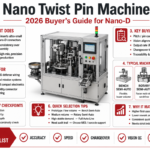
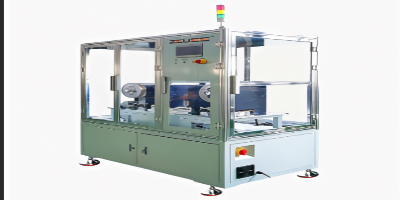
Twist Pin Stress Relief Machine
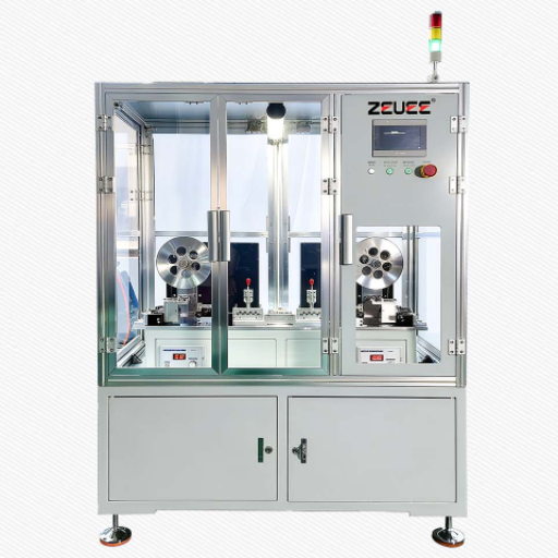
ZEUEE 0.45mm Twist Pin Wire Automatic Stress Relief and Alignment Machine (C49-ZY03-01)
This specifically designed Industrial Wire Straightener machine feeds 0.45mm twist pin wire into the nano-D , Micro-D and hyperbola-shapes connecter’s manufacturing process. This reciprocation (back and forth action ) cycle with multiple wheels makes internally no stress, keeps good linear result: At 4.5-5m/min, keeping consistent speed, keeping the wire straight, module maintenance, broken wire detector and constant-tension feeding, specifically used in aircrafts, defense, and medical connectors.
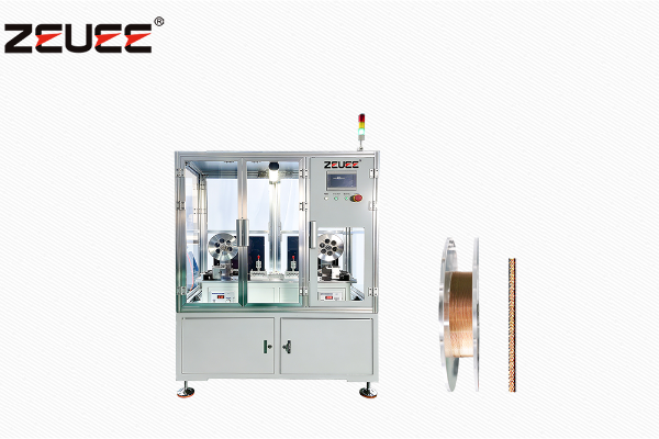
- Model C49-ZY03-01
- Wire 0.45mm twist pin
- Speed 4.5–5 m/min
- Power 5 kW / 220V AC
- Air 0.4–0.6 MPa
- Footprint 1400×800×1850 mm
Why Untreated 0.45mm Twist Pin Wire Cripples Connector Yield
Twist pins are the contact element inside Nano-D and Micro-D connectors used in space, aerospace, defense, satellite and medical products. They’re minuscule — 30 or 32 AWG wire on a 0.025-inch (0.64mm) pin-to-pin pitch in Nano-D, where a 25-position connector weighs about 12 grams (one-eighth the volume of a Micro-D) per the MIL-DTL-32139 interpretation published by Omnetics in Connector Supplier.
Wire that becomes the twist pin starts life on a reel — coil memory, residual drawing stress, and springy recoil after the cut all combine to produce a curved, springy filament when what’s needed is a perfectly straight rod with predictable yield behavior.
NASA-STD-8739.4
This is exactly the failure pattern that the spaceflight wiring workmanship standard NASA-STD-8739.4 targets at the upstream stage, and that the historical patent literature on fine-wire-to-pin connection (USPTO US 4039801) already identified as the root cause of connector pin yield loss in sub-0.3mm wire.
Final Assembly Failure Modalities
As that wire flows downstream and makes its entry into final assembly with poorly-controlled internal stress, 3 types of failure will appear at the panel test station:
01
0.1 mm variation of wirebend
will cause intermittance when the twist pin slides into the hyperboloid socket.
02
The recoil from the wire insertion
will load the pin termination with stress concentrations, noted in a 2025 Hackaday tear-down of the twist-style connection as a very common site of vibration-cracking.
03
Variation in yield strength of wire
in the batch will give a wide variation in performance in the swage press. Connections tolerant of these kinds of problems are tolerant of warranties from satellite primes — which really means they aren’t particularly tolerant.
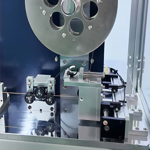
The C49-ZY03-01: Upstream Stress Fixing Mechanism
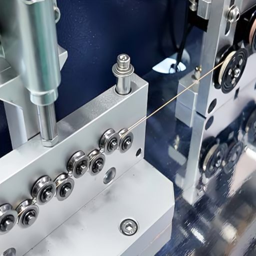
The C49-ZY03-01 provides the upstream, stress fixing just upstream of any station designed for the cable that must accommodate this post-fix wiring, for instance the cutting, swaging, or insertion. As described, it takes the wire from the feed tape, shuttles it back-and forth in a stroke-based stress-relief system, and then passes it through two successive mutually orthogonal, multi-wheeled straighteners and closes on both the original input from the tape spool and the output of the straightening units with its position feedback (Closed Loop Control (CLC) tension controllers, wire break interlock).
This outputted wire exits free of the stresses which would otherwise compromise the connectors’ ability to meet their 200-cycle, 15-milliohm rating with the wire specification MIL-DTL-32139, Omnetics (2017).
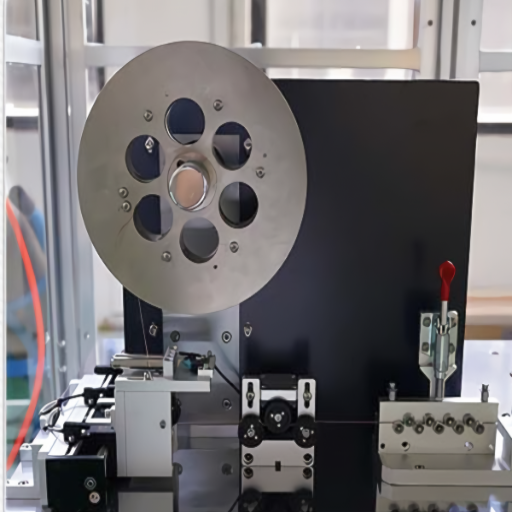
Multi-Wheel Alignment Architecture
Inside the C49-ZY03-01
Four design innovations distinguish “Straightens Wire” from “Manufactures Twist-Pin-Grade Wire”. All specs listed here are sourced from the C49-ZY03-01, now being delivered from our Jiangxi Taihe plant.
| Dimensions (L×W×H) | 1400 × 800 × 1850 mm | Floor-mounted, single-operator footprint |
| Throughput | 4.5–5 m/min | Sustained at 0.45mm wire diameter |
| Rated power | 5 kW | Including drives + tension servos + control PLC |
| Air pressure | 0.4–0.6 MPa | Pneumatic clamping + brake circuits |
| Voltage | 220 V AC, single-phase | 110V / 380V variants available (OEM) |
| Wire diameter range | 0.30 – 0.60 mm | 0.45mm is design center; 0.30/0.60 require roller swap |
| Alignment axes | Horizontal + Vertical | Both axes adjustable on-line via micrometer thumbwheels |
| Tension control | Closed-loop | Eliminates pull variance and stretch |
| Safety interlock | Wire-break auto-stop | Detects breakage in <200 ms and stops motors |
| Construction | Modular sub-assemblies | Stress-relief module + alignment heads removable without disturbing frame alignment |
Constant-Tension Stringing
Servo-driven tension controls mount at each feed and take-up reel. The wire is pulled between spool and spool with a set tension at all times that prevents the characteristic stick-slip.
Wire tension is measured in real time (a measured result, not a dreamed-up setting point) and anything outside the acceptable range forces a line stop to prevent defective wire from progressing.
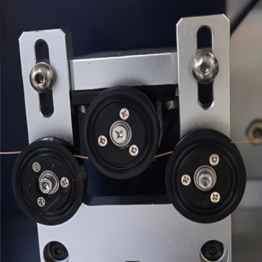
Orthogonal Alignment
Single- axis roller straightening introduces elastic recoil in fine wire. The C49-ZY03-01 elastically deforms material between horizontal and vertical sets of roller wheels.
The cumulative deformation load increasing over staged steps specifically selected to meet sub 0.5 mm copper, brass, phosphor bronze and stainless alloys. The wire holds its final shape at the straightener’s output.
Reciprocating Cycle (RSRC)
While most straighteners are “once through”, feeding wire from entry to exit against rollers, this is insufficient to remove internal stresses in wire smaller than 0.5 mm.
When such a part is cut, internal stresses cause the wire to “recoil” back towards its original curved form. RSRC is a process in which the wire repeatedly travels forwards and backwards through an alignment stage until internal stresses relax.
Modular Maintenance
Independent roller head sub assemblies within the unit allow for ease of maintenance without removing other key modules from the frame or disrupting the overall wire run process.
Any roller replacement or bearing failure is contained within one assembly without the need to disconnect tensioning assemblies. This ensures that our equipment experiences higher meantime between failure rates because each repair event is localized.
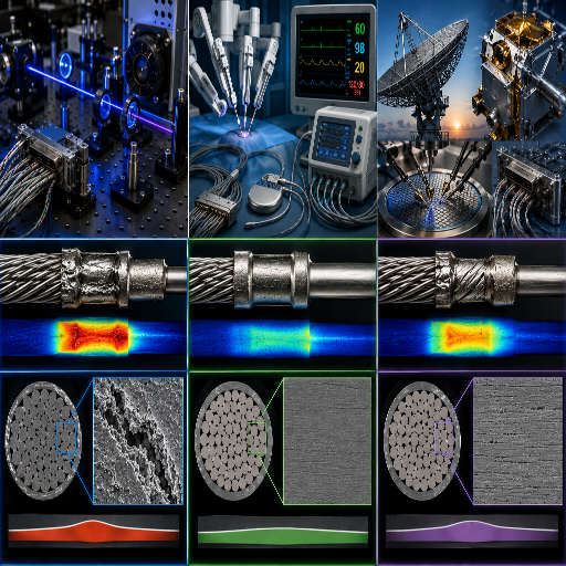
System Ready // Data Matrix
The 0.45mm Twist Pin Wire Stress-to-Yield Reference Matrix
The ability to control the internal stress (the “springiness”) of fine wire directly translates to improvements in connector pin yield and in the contact resistance and other specifications achieved at the connector’s test stage. The following matrix shows what level of internal stress band our RSRC module holds, along with how it impacts wire straightness, and the resulting connector product and its specification-compliance at the connector-building level. MIL-DTL-32139 limits are per the specification (DLA Land & Maritime) and per the connector-engineering interpretation in Connector Supplier (Bob Stanton, Omnetics, April 2017). Patent-layer documentation of the underlying stress-relief approach is captured in USPTO US 4039801.
STRESS-TO-YIELD PERFORMANCE METRICS
Residual Stress Band
Straightness
Pin Assembly Yield
Satisfies Connector Spec
Typical End Use
Below post-RSRC target
≤ 0.5 mm/m
≥ 99.0%
MIL-DTL-32139 Nano-D + MIL-DTL-38999 hyperboloid
Spaceflight cabling, military avionics
Post-RSRC nominal
0.5 – 1.0
97 – 99%
MIL-DTL-32139 Nano-D production lots
Defense electronics, satellite payload
Single-pass roller typical
1.0 – 2.0
92 – 96%
MIL-DTL-38999 only (looser hyperboloid)
Industrial / automotive connectors
Coil memory uncontrolled
2.0 – 4.0
85 – 92%
Commercial connectors only
Consumer / telecom assemblies
As-drawn (no straightening)
> 4.0
< 85%
Unsuitable for MIL-DTL twist pin contacts
Reject lot — back to spool
Stress band — copper
2–3RSRC cycles
15 mΩContact resistance
Soft drawn, yields earliest. Signal-only Nano-D.
Stress band — phosphor bronze
4–5RSRC cycles (Critical)
200+Mating cycles
Holds spring. Standard MIL-DTL twist pin.
Stress band — stainless 304
5–6RSRC cycles (Extended)
−55°C / +200°COperating temp
Highest spring. High-temp aerospace.
Stress band — beryllium copper
4–5RSRC cycles
2,000+High-cycle connectors
Spring + conductivity hybrid. Reusable test connectors.
This isn’t a theoretical table – it’s the tool our application engineers use when recommending the correct wire diameter, alloy type, and number of RSRC cycles. A defense contractor who must ship to MIL-DTL-32139 would never send product that ships with a yield of 92%, as this single low-yield percentage is sufficient to cripple the contractor’s profitability – only those manufacturers landing in the top two rows can ship to that standard, and only through a reciprocating stress relief process. This is not only the deciding factor when you make your purchase, but it’s how we justify our product cost.
Currently experiencing yield vs spec loss? Let’s run a custom stress to yield analysis for your wire and its alloy.
Reciprocating Stress-Relief Cycle vs Single-Pass vs Manual Pre-Straightening
The patent record on this domain is explicit: see USPTO US 4039801 on fine-wire-to-pin connection methods. Conventional rule of thumb says single-pass roller straightening is enough — that is not always true for wire below 0.5mm headed into a hyperboloid contact, because single-pass leaves elastic memory that recoils after the cut.
Process comparison — 0.45mm twist pin wire upstream preparation
| Method | Throughput | Straightness output | Residual stress treatment | Operator skill load | Downstream yield (typical) |
|---|---|---|---|---|---|
| RSRC (C49-ZY03-01) | 4.5–5 m/min | ≤ 1.0 mm/m | Yes — progressive cycle | Low (closed-loop control) | 97–99% |
| Single-pass rotary / roller | 5–12 m/min | 1.0–2.0 mm/m | No — visible curvature only | Medium | 92–96% |
| Manual pre-straighten + cut | ~0.3 m/min (bottleneck) | 1.5–3.0 mm/m | No | High (skilled labor) | 85–93% |
FIG 01. Process Analysis
+
+
Throughput Realities & Yield Correlations
The throughput comparison isn’t real unless the wire passes downline to the spec. Single-pass is faster by count on the specification sheet, but at 92% pin yield, throughput effectively averages to a maximum 96%, before the first rework. The C49-ZY03-01 sacrifices a pair of m/minute on raw speed, but gains 5-7 percentage-points in yield-for a $35 connector going to a defense prime, there’s no more debating that argument.
None of the public sub-1mm wire straightener data sheets we sampled (Cliffeng-SAE 1006-1015; RMG-1.3-12.7mm; Novo Precision-third party service; the WS-800-0.2-0.7mm rotary-and others) report residual stress data or pin yield correlations. They report straightness & rate, half the story.
Put your line against a reference – ZEUEE can help with a process assessment. Request yours now!
Get Instant Quote
SYS.LOC // Positioning
Where the C49-ZY03-01 Sits.
Adjacent patent literature — including USPTO US 5730191 on multi-pin connector straightening tools — shows that the downstream stations either preserve the mechanical state set upstream or pay for it in yield.
This is why owning both stages on equipment built to the same internal tolerance standards matters.
SYS.INT // Interfacing
Equal Process Discipline.
The wire straightener output and the cut-weld process are performed under equal process tolerance discipline. If mechanically stressed wire enters the cut-weld station with variability, the upstream variability compounds with variation of the downstream cut tolerance.
Sharing that discipline throughout the upstream-downstream linkage is the structural underpinning that achieves targeted pin yield numbers for MIL-spec connectors.
The upstream wire straightener defines the capability of the whole line. Everything downstream… depends on it.
The following stage map references ZEUEE product lines simply to provide working equipment context since the process-defining elements of downstream product are built and packaged at exactly the same tolerances.
ZEUEE Wire-Prep Map
PROC.SEQ 01-0601
Upstream (This)
0.45mm wire stress relief & alignment
(C49-ZY03-01) produces stress-relaxed straight wire ready for the next phase.
02
Midstream
Twist pin cutting & welding
Laser cuts to length, seamlessly welds braided ends to the solid pin shaft.
03
Micro Pin
Micro twist pin assembly
Engineered for hyperboloid contact builds specifically within the Micro-D format.
04
Nano Pin
Nano twist pin assembly
Precision execution for Nano-D and full MIL-DTL-32139 specification production.
05
Integration
Connector cable assembly
Installs finished twist pins securely into connector shells for full cable builds.
06
Finishing
Contact color-ring coating
Automated MIL-DTL color band marking ensuring strict compliance with M39029 BIN codes.
Aerospace, Defense and Medical — Where 0.45mm Twist Pins Earn Their Keep
Executive Summary
The twist pin is the contact element that lets a Nano-D or Micro-D connector squeeze 51 pins into a package smaller than your thumbnail and hold its grip across mating-cycle counts that consumer connectors never see. The MIL-DTL-32139 spec, maintained by DLA Land & Maritime, defines this category, and the applications below are the buyer set the C49-ZY03-01 was designed for.
Aerospace and Spaceflight
Application Specs
Cable assemblies meeting NASA-STD-8739.4 workmanship standards for spaceflight hardware rely on Nano-D and Micro-D twist pin connectors on satellite payloads, instrument racks and avionics buses. Vibration during launch and thermal cycling on-orbit punish any pin that has residual stress at its termination – exactly the failure mode that upstream RSRC was designed to eliminate. Customers running these assemblies cite the 55C to +200C MIL-DTL-32139 operating envelope as a hard line for wire pre-treatment quality.
Defense Electronics
Application Specs
MIL-DTL-32139 and MIL-DTL-38999 connectors populate radar arrays, sonar buses, weapon-systems telemetry, and missile guidance cable runs. Defense primes audit the upstream supply chain down to the wire spool, and they want to see process control on the alignment stage, not just an end-of-line spec sheet. The reciprocating cycle is auditable – cycle count and tension log are recorded by the PLC and exportable for the buyer’s quality file.
Medical Devices and Diagnostics
Application Specs
Implantable lead frames, surgical robotics control cables and patient-monitor multi-channel assemblies use the same fine-wire twist pin architecture. ISO 13485 supplier audits care about lot traceability and consistent mechanical state – both of which the C49-ZY03-01’s tension log and modular changeover support. Wire diameter steps for medical lines are tighter (often 0.3 and 0.4mm); the roller swap accommodates this in a 15-minute changeover.
Precision Instruments and Photonics
Application Specs
Optical fiber alignment fixtures, semiconductor probe-card assemblies, scientific instrument feedthroughs – anywhere a hyperboloid contact is preferred over a stamped pin for its mating force and cycle life – uses wire pre-stressed exactly the way the matrix above describes. A single C49-ZY03-01 configuration ships into all of these — only the alloy, diameter and RSRC cycle count change.
What connects these applications is not the industry — it is the cost of a failed connector in the field. An aerospace prime can’t afford to discover the bad pin after launch. A defense buyer can’t afford it after fielding. A medical OEM can’t afford it after implant. Upstream wire pre-treatment is where that cost is bought down, and the C49-ZY03-01 is the production-grade stage that buys it down.
Building to MIL-DTL-32139, MIL-DTL-38999, or ISO 13485? Schedule a 15-min spec consultation with our application engineering.
Get Instant QuoteProcurement Guide — Lead Time, OEM Range, Spare Parts, Service Coverage
The buyer looking at C49-ZY03-01 is comparing it across the spectrum to alternatives — a $2,000 imported single-pass straightener from Amazon at one end, a $200,000+ European wire processing cell at the other. The procurement framework below models the cost driver and total cost factors; this is the information that feeds the inputs used in the quote conversation:
Ready to tailor a config? Get FOB pricing by wire diameter – submit your scope for a 5 day quote.
Get Instant QuoteZEUEE Manufacturing Provenance and Certifications
Your wire preparation you put upstream of your connector pin assembly is going to be in service for ten or more years. Your vendor needs to be in service for at least that long. ZEUEE (Shenzhen Zeyu Intelligent Industrial Science Technology), builds industrial automation equipment. They were founded in 2005, so they have been doing this for more than a decade. Here is the stack for ZEUEE to answer your question of origin. This will answer who it is, how it’s qualified, who else trusts it and how deeply engineered it is:
ZEUEE Manufacturing & Certification Stack
01
Founded 2005 – over two decades of automation equipment build history
02
20,000 m production facility in Taihe, Jiangxi, with Shenzhen HQ
03
120+ employees across R&D, build, QC, and field service
04
Quality management: ISO 9001:2015 certified
05
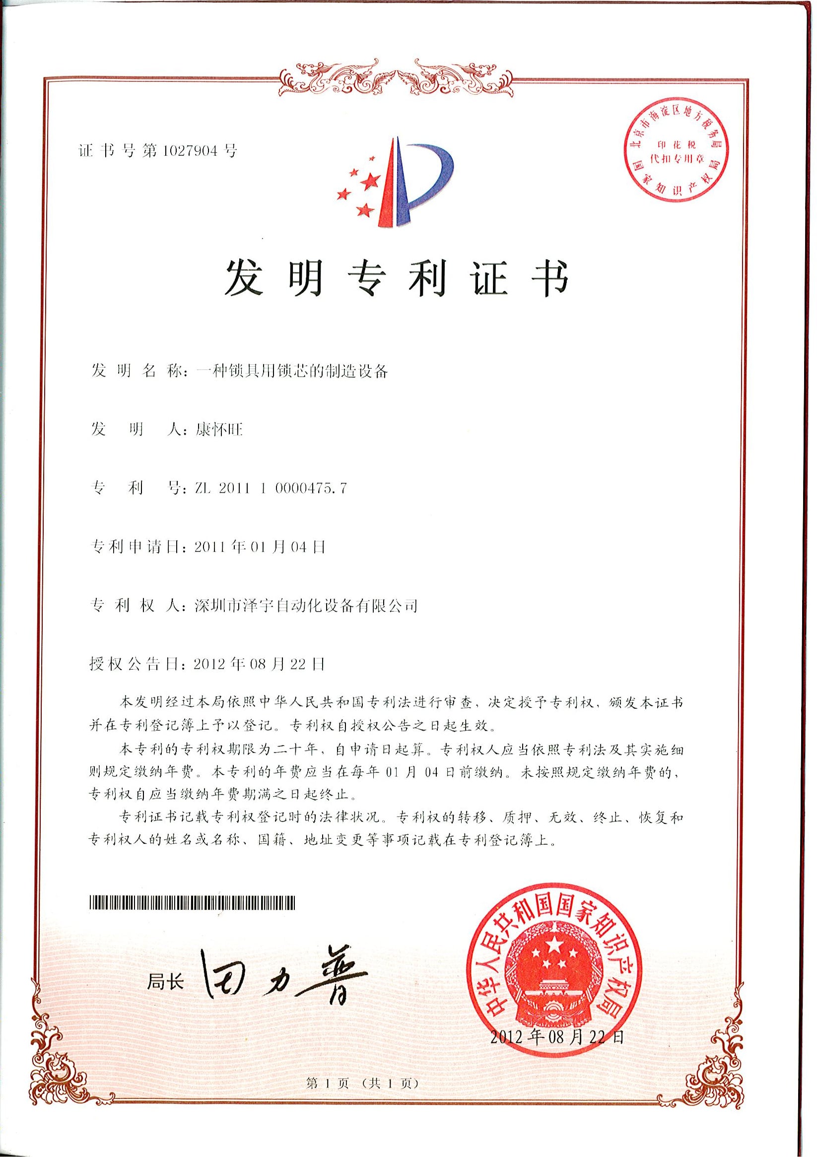
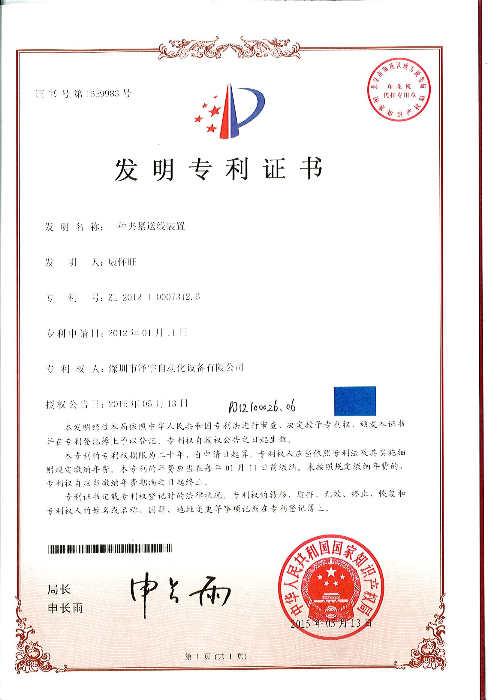
Patent portfolio: 32+ invention patents, 68+ utility model patents, 150+ R&D patents total
06
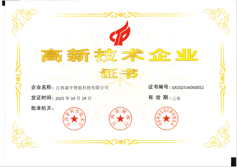
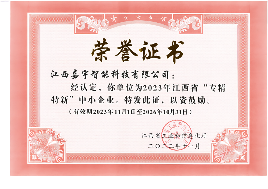
Recognition: National High-Tech Enterprise; Specialized & Sophisticated Small Giant Enterprise designation; Patent Demonstration Enterprise
07
Industry standing: Vice-President Unit of Guangdong Robot Association; Council Member of Shenzhen High-Tech Industry Association; Member Unit of China Intelligent Manufacturing Industry Alliance
08
Long-term customers include AVIC, China Shipbuilding, GAC Group, Corning USA, Hunter, TE, Sumitomo Japan, LEGO Denmark, TCL, SONY, Foxconn
09
Equipment in service across 30+ countries
10
Standards referenced: MIL-DTL-32139, MIL-DTL-38999, NASA-STD-8739.4, ISO 9001:2015
Documented Archives
×
![]()
Twist Pin Stress Relief Engineering & Optimization Tools
Wire & Alloy Requirement Analysis
Select your parameters below. Our engineering logic computes the recommended Reciprocating Stress-Relief Cycle (RSRC) count, straightness tolerance, and connector compliance specifications.
Yield Lift TCO Estimator — Upstream Stress Relief Impact
Estimate the annual gross-margin recovery your line picks up when wire stress relief moves from single-pass to RSRC. Numbers are framework estimates from the Stress-to-Yield Matrix — Gold-tier custom TCO available with your line data.
MIL-DTL Compliance Checklist — 0.45mm Twist Pin Wire Pre-Treatment
Check each item your current upstream wire-prep line satisfies. The score maps to MIL-DTL-32139 audit readiness for Nano-D twist pin assembly. Eight items, all must pass for production-grade audit-ready status.
FAQ — Procurement and Engineering Questions Buyers Actually Ask
[ 01 ]
What wire diameters does the C49-ZY03-01 process?
Standard scope: 0.30 to 0.60mm, with 0.45mm as the design center. Changeovers for diameters within the range are done in ~15 min by replacing the entire roller set. For orders of less than 0.30mm and greater than 0.60mm, these configurations are handled via OEMs and ship accordingly.
[ 02 ]
How does reciprocating stress relief differ from single-pass wire straightening?
A single pass straighten operation pushs the wire once through the alignment roller-set and accepts the result. However for wires below 0.5mm in diameter, they recoil after cut due to having memory; this process doesn’t have enough opportunity to reduce internal stress to that of the point to which it has yield and subsequent set. The reciprocating stroke process (RSRC) allows the wire to advance back and forth through the alignment roller-sets to accumulate the number of elastic yield/set cycles required to sufficiently drop the internal stress down to a value at which the downstream connector pin assembly will not see unacceptable deformation. RSRC is significantly slower by measured specs (it only provides ~2 m/min when “set on spec”), but it results in wire that a connector pin assembly machine can accept; that makes more efficient production than the faster (up to 5 m/min by measured specs) but “memory rich” result from a single pass process.
[ 03 ]
What residual stress level is required for MIL-DTL-32139 or MIL-DTL-38999 connector assembly?
What is the applicable spec that will inform you? The downstream connector is the “source of truth”, which in this case is specified to achieve “200+ cycles and <15mΩ contact resistance per MIL-DTL-32139” for our Nano-D connectors. The chart of a Stress-to-Yield Matrix above provides the optimal values (straightness of <1.0 mm/m with 97%pin assembly yield) desired within the system. Each specific alloy mix has an unique stress reduction/relaxation behavior determined during the application engineering process; an alloy specific cycle curve is provided to support your processes and quality efforts.
[ 04 ]
What is the sustained throughput at 0.45mm versus 0.50 or 0.30mm wire?
Sustained throughput at 0.45mm sits at 4.5-5 m/min — the design center. 0.50mm will run at the top of this band or slightly higher (it tolerates increased speed with little loss in alignment.) 0.30mm wire will run at the bottom of the band to enable the RSRC cycle to achieve additional passes required to allow the finer wire to relax. Customer’s running days mixed between diameters sequence the wire in according to switch over, not speed difference.
[ 05 ]
Does the machine handle copper, brass, phosphor bronze, beryllium copper, and stainless steel twist pin wire?
Yes.
These five constitute the standard alloy suite which the Stress-to-Yield Matrix is calibrated to, and customer’s specification requires OEM application engineers to confirm appropriate RSRC cycles and tensions on a specific alloy based on an application engineer during spec-build. Silver bearing copper, nickel titanium medical lead forms are possible on a consultative OEM basis, subject to in-shop tests.
These five constitute the standard alloy suite which the Stress-to-Yield Matrix is calibrated to, and customer’s specification requires OEM application engineers to confirm appropriate RSRC cycles and tensions on a specific alloy based on an application engineer during spec-build. Silver bearing copper, nickel titanium medical lead forms are possible on a consultative OEM basis, subject to in-shop tests.
[ 06 ]
What is the ZEUEE FOB price range and standard lead time?
FOB pricing depends on the six scope factors covered above: wire diameter span (0.30–0.60mm standard, OEM extends), alloy mix, voltage variant, shipping origin, OEM customization scope, and the spare-parts kit. Lead time sits in the band typical for production-grade automation built to specification, with the formal commitment captured in the quote. We don’t publish a single price on the website because configuration variance is real, and a number that ignores your scope will either over-promise or over-quote.
[ 07 ]
How does upstream stress relief impact downstream connector pin assembly yield?
Experience has shown, and MIL-DTL specification indicates that yield improvements of several percentage points are possible when supplier wire residual stresses are lowered below the band shown after the RSRC process in the below graph. Individual gains depend on alloy used, destination cut/weld accuracy, and product inspection parameters, of course. Forecast for any specific customer are predicted by overlaying the Stage Position Map to the Stress-to-Yield Matrix calibrated for the customer specified alloy and connector specification, and Benchmarking to prior C49-ZY03-01 production run data across our Nano-D and Micro-D production facilities. Two to five percent gains are estimated for Nano-D applications over existing post RSRC nominal in the band depicted; lesser amounts for copper only applications, greater gains for high cycle, medical beryllium copper test connectors.
[ 08 ]
What maintenance is required for the multi-wheel alignment mechanism?
Basic maintenance for this unit includes bearing lubrication for the alignment head on a monthly schedule, regular testing of the tension encoder output signals and replacement of tension guide rollers at the intervals stated in the parts kit. Alignment heads are modular components, and removal or replacement of a tension guide roller takes less than one shift and does not require frame disassembly or re-tensioning of the process chains. MTBF is based on total operating time for each specific unit and provided to the customer as part of the commissioning document.
Application Engineering
Specify the C49-ZY03-01 for Your Connector Pin Line
Provide your wire scope (diameter and alloy), throughput target, and connector specification - our application engineering team will send back an off-the-shelf quote including configuration and associated OEM specifications within 5 business days FOB at your requested ship date.
WHY WE WRITE THIS
About ZEUEE Engineering Insights
ZEUEE shares technical guides based on real automation project experience. Since 2005, we have designed and manufactured non-standard automation equipment for connector assembly, wire harness production, robotic lines, vision inspection, and smart factory upgrades.
Founded in 2005
20,000 m² production base
120+ specialists
150+ R&D patents
ISO9001:2015 certified