Get in touch with Zeyu lntelligent Industrial Company

Toy Assembly Machine Guide: From Product Family to Acceptance

Updated October 2026 · Written by Cherry
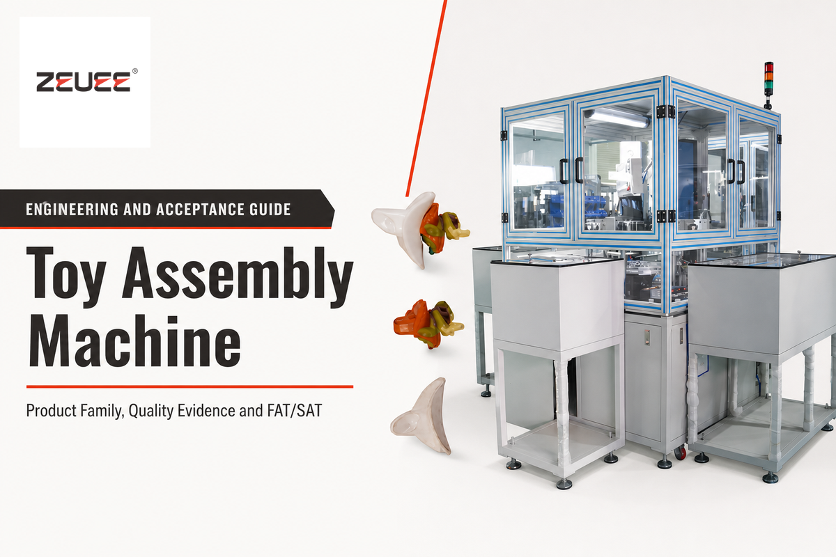
A toy assembly machine is an industrial production system that feeds, joins, verifies, records and releases components for a defined toy or toy family. It is not one universal machine category. Wheeled toys, electronic figures, plush modules, and multi-part playsets create different part-presentation, joining, inspection, safety, and traceability problems.
This guide explains how to prepare the engineering evidence before choosing a machine concept. It deliberately leaves equipment configurations, published specifications, pricing, lead time, and quotation to ZEUEE’s commercial solution page. It helps the manufacturing team define the problem, and distinguishes this document from an advertisement or second sales page for the same keyword.
Quick answer
Plan a toy assembly machine by freezing the product-family boundary first. Then prove component presentation, orientation, joining access, inspection visibility, safety and quality evidence, qualified output, variant release, fault recovery, and acceptance conditions. Successful machine runs provide useful evidence, but they don’t automatically certify the finished toy or prove sustained production capability.
The evidence path in one view
| Product boundary | Named family, revisions, incoming component states, included operations, released output |
|---|---|
| Readiness proof | Feedability, datum, tolerance, access, surface handling, inspectability, variant identity |
| Control proof | Requirement, process risk, control, verification, record, reaction, release owner |
| Output proof | Observed opportunities, losses, accepted pieces, release holds, stated operating window |
| Acceptance proof | Agreed samples, challenges, conditions, raw results, deviations, owners, signatures |
1. What Is a Toy Assembly Machine in an Industrial Factory?
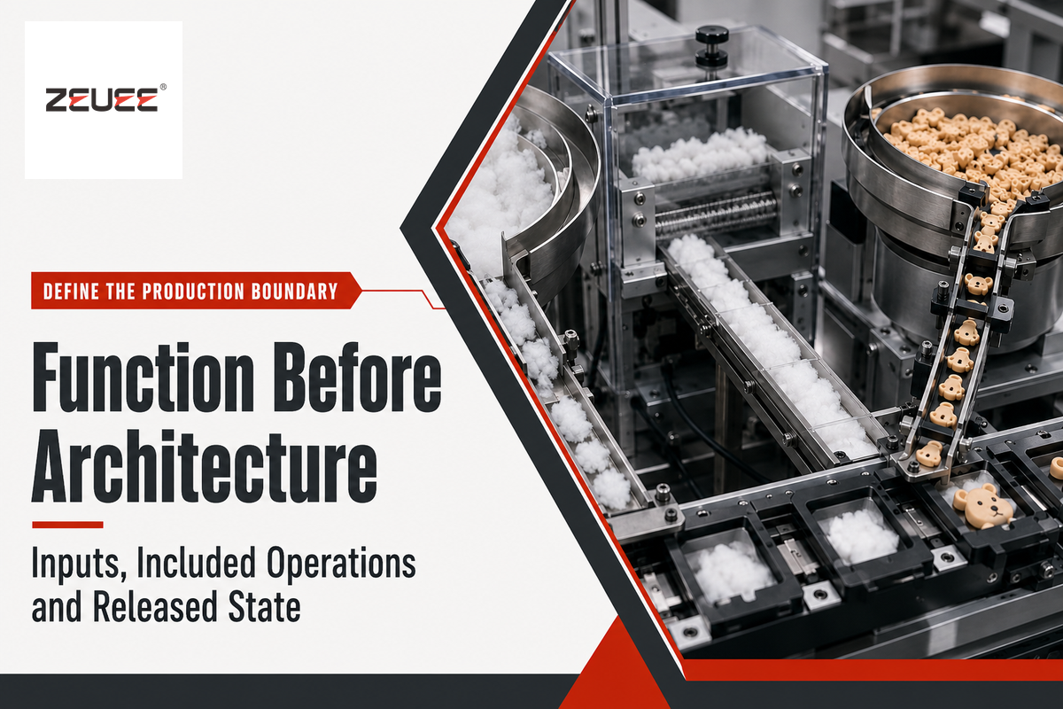
The term “toy assembly machine” describes a function, not a fixed architecture. The system might receive molded shells, wheels, axles, fasteners, printed parts, electronic modules, fabrics, springs, or packaging subassemblies. It may identify a variant, establish a datum, perform one or more joints, verify selected characteristics, contain uncertain units, and create a production record.
Start by distinguishing assembly from adjacent processes. For example, plastic injection molding produces a plastic component; decorative printing is another adjacent process. Electronic testing may qualify a purchased module. These adjacent processes can connect to an assembly line, but their inputs, failures, and release evidence should not disappear inside the word “machine.”
The industrial definition prevents a search-intent error. Consumer results might use “toy assembly” for a kit, puzzle, model, or activity a child completes. In this case, the subject is factory automation, operated in a controlled manufacturing process. The released output is a product or subassembly whose identity and acceptance status are known.
In practice, the scope statement is: “The system receives these identified components in these controlled states, performs these included operations, and releases this defined output with these records.” If a team cannot complete that sentence, it is too early to compare station layouts or output claims.
2. Freeze the Product Family Before the Machine Concept
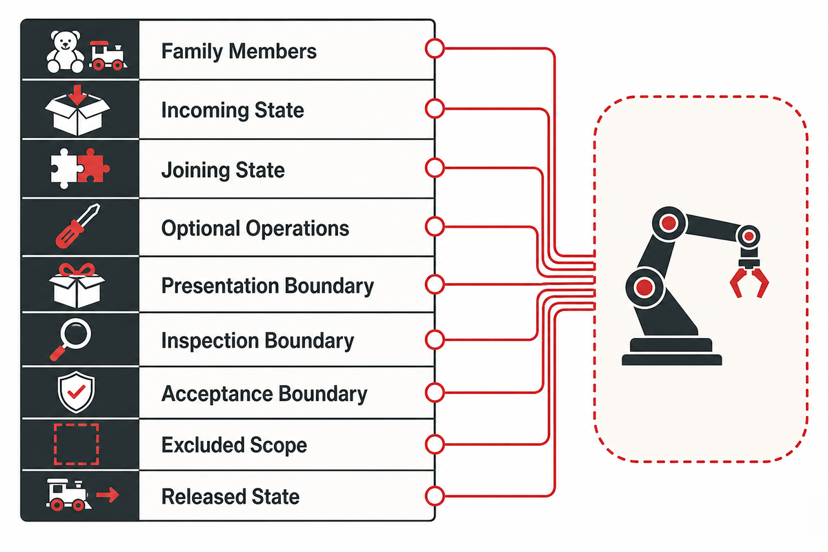
It isn’t uncommon for a project to begin with a target rate and multiple drawings. The more challenging question is whether those products truly belong to the same automation family. Two toys may look similar to a customer while presenting different datums, joining access, surface risks, or inspection cues to a machine.
Before determining the mechanism, use a Toy Product Family Boundary Sheet. Product engineering should own the design truth, plant engineering the interfaces and operating context, and quality the defect and release definitions.
9-Field Toy Family Boundary Matrix
| Boundary category | Record | Why it changes the concept |
|---|---|---|
| Family members | Part numbers, revisions, representative and boundary variants | Defines the contracted envelope rather than an open-ended promise |
| Incoming state | Tray, reel, stack, bulk, bag, carrier, film, protective separator | Changes feeding, replenishment, damage, and labor |
| Joining state | Press, fasten, weld, bond, clip, stake, snap, sew, or manual assist | Changes access, fixtures, signals, and verification |
| Optional operations | Variant-specific components, labels, tests, decorations, packs | Creates bypass logic and changeover proof |
| Presentation boundary | Approved containers, orientation, lot variation, replenishment state | Defines the feeding evidence rather than assuming ideal parts |
| Inspection boundary | Characteristics, method, challenge pieces, reaction and record | Separates what the station can verify from what remains external |
| Acceptance boundary | Factory conditions, site conditions, samples, deviations, owners | Prevents a witnessed run from becoming an unlimited promise |
| Excluded scope | Molding, component certification, offline cure, packaging, laboratory tests | Stops a later assumption from becoming unpaid machine scope |
| Released state | Accepted subassembly or toy, identifier, data record, downstream interface | Defines what “complete” means |
Don’t average incompatible variants to create a fictitious “representative toy.” A boundary variant may be the lightest component, the most reflective color, the smallest joint, the largest tolerance stack, or the least visible feature. The sheet doesn’t pick equipment. It identifies which assumptions the equipment concept must survive.
3. Is the Toy Ready for Automated Assembly?
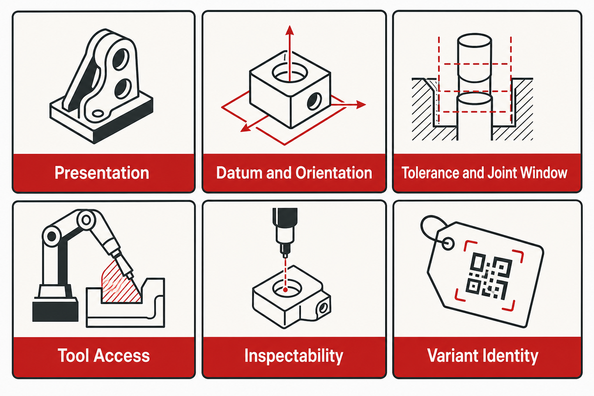
Volume is not an automation-readiness test. Even a high-volume toy component can still nest in bulk, arrive with unstable flash, hide its orientation, mark easily, flex away from a datum, or lack a feature that an inspection method can see.
Create an “Automation Readiness Evidence Grid” with four separate columns: domain, evidence to bring, failure pattern, and next owner. Focus on real lots and approved alternates, not only on ideal prototypes.
- Presentation: Can parts be separated and replenished without mixing, tangling, bridging, or cosmetic damage?
- Datum and orientation: Which geometry establishes pose, and can the wrong pose appear stable?
- Tolerance and joint window: Do component extremes still allow insertion, clamping, engagement, and release?
- Tool access: Can a driver, gripper, horn, press, dispenser, camera, or gauge reach the required feature without creating a new risk?
- Inspectability: Is the characteristic observable under controlled lighting, contact, force, motion, or functional conditions?
- Variant identity: Can tooling, recipe, material, product, and record remain bound through changeover and rework?
NIST’s work on tolerances and uncertainty in robotic systems notes that part tolerances, measurement uncertainties, placement, and robot capabilities must be connected. Its assembly performance test methods vary part size, shape, position, type, task orientation, and access.
Precise pre-positioning and camera inspection are not universal prerequisites. It still depends on bounded geometry, a stable grasp, controlled contact, and a defined search region. Readiness means that the chosen method has evidence across the agreed variation, not that every product must use the same sensor or feeder.
Keep all measurements tied to the project. A worksheet may express location in mm, force in N, time in s or ms, pressure in kPa or bar, temperature in °C, speed in rpm, mass in kg, frequency in Hz, electrical load in W or kW, voltage in V, current in A, and rates in %. Values such as ±0.10 mm, 25 N, 500 ms, 20 kPa, 1 bar, 40 °C, 30 rpm, 2 kg, 50 Hz, 0.1 kW, 24 V, 2 A, or 10% are examples of units and notation only; none is a toy-assembly limit until an approved product and process method establishes it. The same rule applies to any record written as 2 sec, 5 min, 1 hr, 3 days, 4 months, 1 year, 10 cm, 20 μm, 5 psi, 1 MPa, 4 kWh, 5 m², 6 m³, 7 MHz, 8 t/h, 9 oz, 10 lbs, or 11 nm: a unit makes a statement measurable, but only the approved method makes its value relevant.
4. How Toy Assembly Works Without a Universal Line Recipe
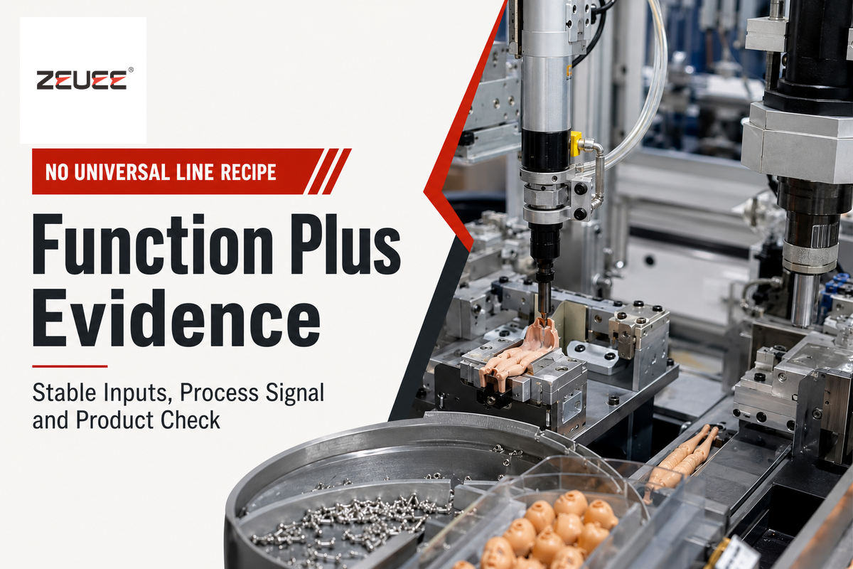
The project needs qualified owners for both layers. For example, a concept may break down into blocks such as identify, feed, singulate, orient, datum, join, verify, inspect, contain, record, and transfer. Hardware selection comes later. One project may use bowls and hard tooling; another may use trays, flexible feeding, robots, indexing, conveyors, or controlled manual assists.
| Function | Condition that must be stable | Evidence that matters | Typical failure question |
|---|---|---|---|
| Feed and singulate | Delivery state and separation behavior | Lot trials, replenishment, damage, jam observations | Does one easy lot hide nesting or bridging? |
| Orient and datum | Distinguishable pose and controlled locating surface | Pose confirmation and boundary geometry | Can a wrong orientation pass presence detection? |
| Join | Materials, access, fixture, tool, process window | Force, displacement, torque, energy, dispense, time, or product result | Does a completed motion mean an accepted joint? |
| Inspect and contain | Visible characteristic and known disposition rule | Challenge pieces, reject route, suspect-population logic | Where does an uncertain unit go? |
| Record and transfer | Identity continuity and downstream handshake | Forward/reverse retrieval and blocked/starved states | Can correct data attach to the wrong toy? |
Different process signals are created from screwdriving, press fitting, ultrasonic welding, dispensing, snap assembly and others. These signals must be correlated with the product characteristic they’re meant to protect. Torque results don’t necessarily indicate retention. Dispense confirmation does not prove cured bond strength. The camera can only assess the characteristic, pose, surface, lighting and field of view that are part of its method.
Manual work is a process step that should be evident in process maps. An operator who untangles parts, cleans a lens, applies a difficult component, or releases a first piece changes staffing, time, safety, and genealogy. Controlled manual work remains acceptable. An undocumented one makes the acceptance basis incomplete.
5. Translate Toy Safety and Quality Requirements Into Station Evidence
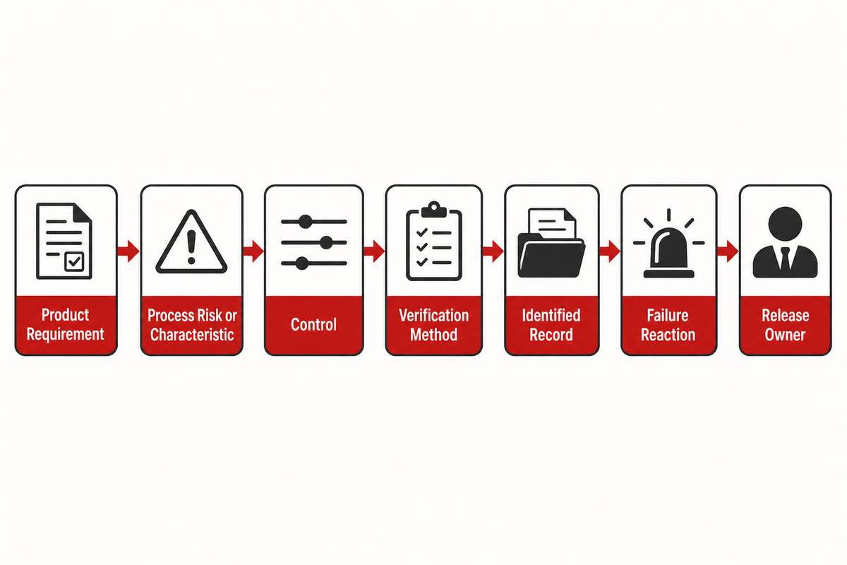
The most effective control plan starts with the product requirement instead of the available sensor. Use a Toy assembly Evidence Chain: requirement → process risk or characteristic → control → verification method → identified record → failure reaction → release owner.
Manual work should be visible in the process map. For example, a small component that must be present might need material identity at loading, pose confirmation before joining, an assembly-process signal, a finished-state check, a defined reject route, and a record associated with the right unit or lot. The control plan depends on the requirements of the product and market, as well as the risks and the applicable conformity routes.
The U.S. Consumer Product Safety Commission’s toy-safety guidance explains the finished-product regulatory context, and the Federal Register identifies ASTM F963-23 in the U.S. toy rule. Machinery evidence has a different scope. The public ISO 12100 catalogue page concerns machinery design, risk assessment, and risk reduction. Machine risk reduction protects people interacting with equipment; it does not certify the finished toy.
The reverse is also true: a product test does not establish adequate guarding, safe control functions, or hazardous-energy procedures. OSHA distinguishes normal-production guarding from servicing and maintenance conditions. The project requires qualified owners for both.
Three evidence boundaries
- Component or station evidence doesn’t automatically replace an applicable finished-product test.
- Internal station genealogy isn’t the same control as consumer-facing tracking marks on the product or packaging.
- Vision results, machine declarations, or successful recipe changes can’t by themselves prove every product-compliance obligation.
Regulatory timing requires attention. The European Commission states that Regulation (EU) 2025/2509 entered into force on January 1, 2026 and applies from August 1, 2030 after transition. In this context, the entry into force isn’t the same as the full application. Confirm the current market and product obligations with qualified compliance counsel rather than copying a machine checklist between jurisdictions.
6. Model Qualified Output, Not Nameplate Cycle Time
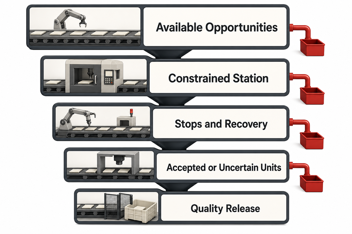
Fast local operations aren’t the same as released output. The feeder can starve the joint station. Downstream inspection can block transfer. Micro-stops can consume operating time. Rejects, rework, record errors, and release holds can reduce usable pieces even when the nominal cycle looks attractive.
The Qualified-Piece Constraint Cascade makes those losses visible:
- Component presentation creates available opportunities.
- The constrained station sets the fastest possible handoff for the current sequence.
- Stops, replenishment, recovery, and blocked/starved states remove opportunities.
- Inspection and process rules separate accepted, rejected, uncertain, and rework units.
- Quality release determines which accepted units count as qualified output.
An illustrative reconciliation is qualified pieces per hour = observed run opportunities × first-pass yield × release fraction. It is not an equipment guarantee and should not be used with guessed inputs. The owner of each factor should provide a measurement window, product mix, material condition, staffing assumption, reject rule, and data source.
| Factor | Evidence source | Owner | Optimistic-assumption warning |
|---|---|---|---|
| Run opportunities | Timestamped station and line states | Plant engineering | Do not use one operation time as the whole line |
| First-pass yield | Accepted, rejected, and rework results | Quality | Do not count repaired units twice |
| Release fraction | Hold, review, genealogy, and final disposition records | Quality and operations | A physically complete unit may still be on hold |
In the handbook of the National Institute of Standards and Technology (NIST), it’s stated that stability must precede capability assessment. NIST does not present that statement as an FAT or SAT rule. This guide therefore makes a bounded engineering inference: report a finite acceptance run as witnessed project evidence, not as automatic proof of sustained process capability. The handbook’s sample guidance remains in its statistical context and is not a universal FAT duration or sample count.
“Process stability must be established before capability is assessed.”
7. Control Product Variants With a Proof Loop
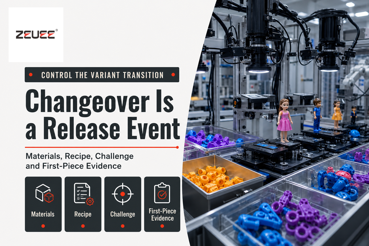
The recipe number alone can’t complete a changeover. Variant identity may affect incoming parts, feeder tooling, nests, join programs, camera profiles, test limits, labels, data fields, and the physical route through optional stations.
Use a Variant Proof Loop:
- Close the prior order and identify its last accepted unit.
- Reconcile and remove prior materials, labels, work in process, and uncertain pieces.
- Apply the required safe setup or energy-control state before exposed tool work.
- Install and verify change parts, tooling, sensors, and fixtures.
- Load the approved recipe, limits, inspection profile, and label data.
- Run predefined known-good, known-nonconforming, or boundary challenges where the method supports them.
- Review the first released pieces and every required record.
- Authorize sustained production with a named release owner.
Evidence volume depends on risk, process behavior, the product family, applicable requirements, and the agreed control plan. “Ten good pieces” is not a method unless the project explains why ten, which characteristics were checked, which variation was represented, and what would trigger more evidence.
Compliance-impacting changes require a separate decision. Sourcing a new supplier, a different process or material, or other inputs may affect the need for product testing and certification. Successful mechanical changeover proves only the demonstrated machine and quality checks; it does not automatically clear the regulatory effect of the change.
Keep the safety release separate from the product release. The applicable scope of OSHA’s hazardous energy standard addresses the servicing and maintenance of equipment where unexpected energization or stored energy could cause an injury. The control button doesn’t isolate energy.
8. Plan Factory and Site Acceptance as Two Evidence Events
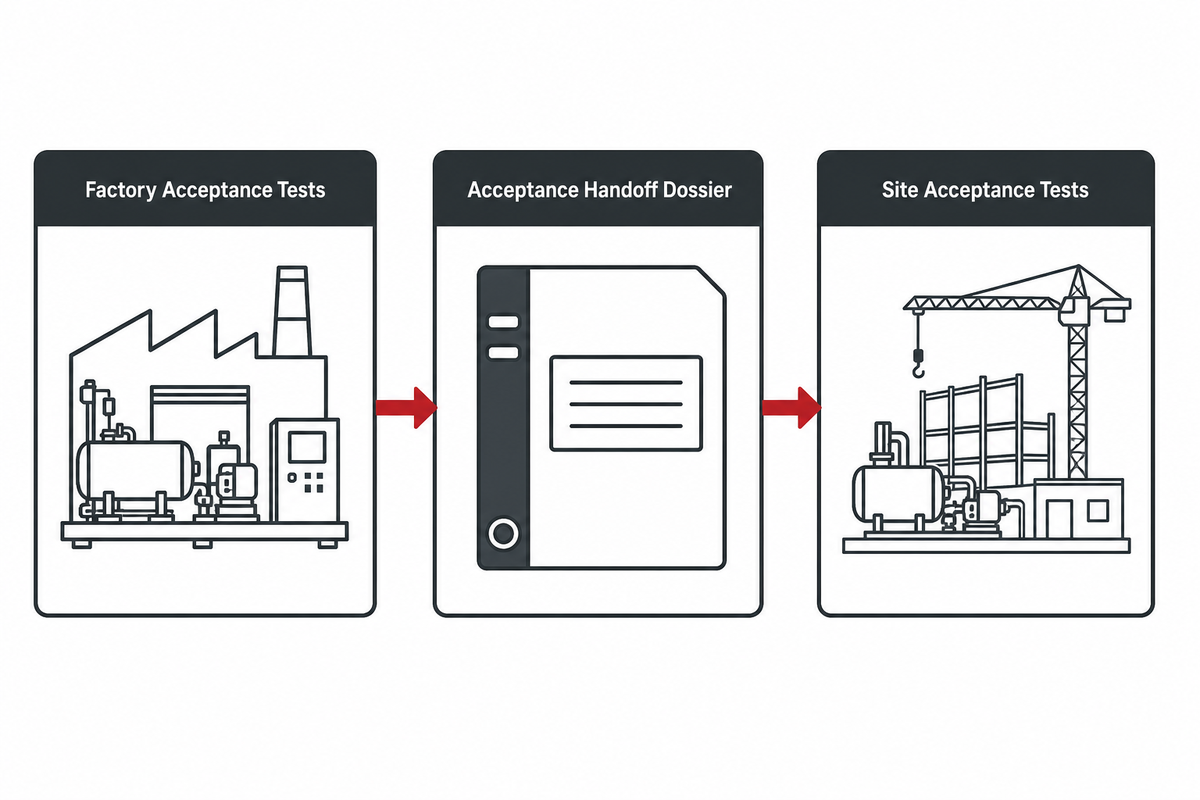
Factory and site acceptance testing have related, but different, purposes. Factory acceptance tests are performed before shipment under documented supplier conditions. Site acceptance tests occur after installation and address the assembled site’s utilities, interfaces, materials, operators, data connections, and intended operating conditions.
A practical manufacturing report on debug, checkout, startup, FAT, and SAT describes this separation. Consider it industry practice, not regulation. The terms of the contract and approved test protocol should be relied on to determine the parties’ actual obligations.
| Evidence event | Typical questions | What it does not prove alone |
|---|---|---|
| FAT | Agreed machine scope, samples, guarding functions, process windows, failure reactions, records, deviations | Installed utilities, every future lot, sustained capacity, finished-toy certification |
| SAT | Installation, site safety, interfaces, upstream/downstream behavior, operators, materials, data and release conditions | Long-term stability, every variant, continuing product-compliance obligations |
Create an Acceptance Handoff Dossier, which includes approved scope, product and boundary-sample identity, test conditions, raw results, stops, rejects, interventions, deviations, open actions, training, documents, spares, and decision owners. Every deviation must have an owner and a closure path, and “accepted with comments” isn’t acceptable for a production handoff.
Agree on duration, variants, and challenge conditions and decision logic in advance. A product-lot acceptance plan is a separate statistical decision. Acceptance sampling plans are directly related to producer and consumer risks, and specified quality levels, according to NIST. A worked sample size isn’t a universal number for machine functionality, integration, or capability.
Finally, FAT and SAT don’t remove the requirement for continued control over the production process. A finite evidence event can demonstrate what happened under specific conditions. It can’t, by itself, prove sustained capability or every future product-compliance duty.
9. Maintain the Line by Failure Signature
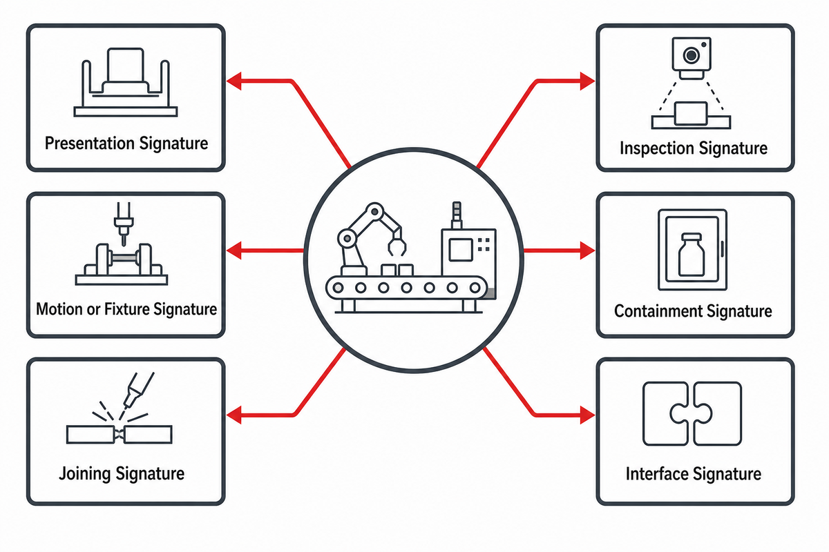
“Downtime” is too broad for corrective action. Classify losses by failure signature and tie each event to the product, variant, material, tooling, recipe, and line state at the time of the loss.
- Presentation signature: empty pick, double feed, nesting, bridge, orientation escape, refill disturbance.
- Motion or fixture signature: datum miss, clamp state, wear, collision, lost position, change-part error.
- Joining signature: torque, force, displacement, energy, dispense, cure, seating, tool-life trend.
- Inspection signature: image quality, gauge state, false accept/reject, lost sample, challenge failure.
- Containment signature: reject-bin state, uncertain routing, suspect population, rework or genealogy break.
- Interface signature: blocked or starved transfer, upstream identity mismatch, downstream release hold.
Record the observation, safe intervention, impacted population, correction, confirmation method, and release owner. “Reset and ran” is not enough when the interruption can mix variants or lose the last-known-good boundary.
Recovering a safe state depends on the task being performed, and the exposure created. Adjusting a guide, clearing a jam, removing a tooling piece, or cleaning a sensor may expose a person to a hazard. Classify the activity against the applicable guarding and hazardous-energy rules; do not treat every normal-production intervention as a minor exception.
Changes to component drawings or assemblies can invalidate evidence. Change control should reopen the relevant readiness, process, inspection, or acceptance proof rather than assume the previous result transfers. It is to connect a failure signature to the evidence owner who can prevent recurrence and make a defensible restart decision.
10. What to Prepare Before a Custom Machine Discussion
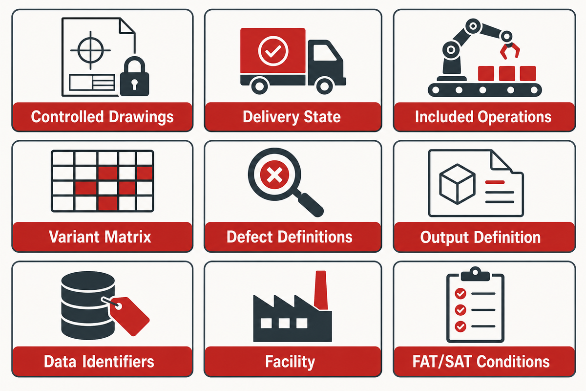
Effective engineering review begins with the production of an evidence-ready brief rather than with target speed. Prepare representative and boundary samples, product-family rules, incoming component conditions, the current assembly sequence, joining criteria, known defects, traceability needs, facility interfaces, and the people who own acceptance and release.
Minimum discussion package
- Controlled drawings, revisions, bill of material, physical parts, approved alternates
- Delivery state, lots, surface limits, handling risks, geometry and orientation cues
- Included operations, joining criteria, process evidence and product checks
- Variant matrix, change parts, recipe ownership and first-piece release method
- Defect definitions, challenge samples, reject handling, rework and containment
- Output definition, product mix, operating window, stops, replenishment and staffing
- Data identifiers, tracking requirements, records, retention and system interfaces
- Facility, utilities, machine-safety ownership, maintenance access and intervention states
- FAT/SAT conditions, responsibilities, raw evidence, deviations and sign-off rules
After that’s in order, consult the ZEUEE Custom toy assembly machine solution for application-specific equipment and commercial discussion. Configuration, published performance, pricing, lead time, quotation, and RFQ remain on that page rather than being duplicated here.
The About ZEUEE page will provide additional first-party information on the company. The technical boundaries in this guide remain tied to the public sources and limitations listed below.
Key takeaway
A defensible toy assembly project connects the product family, component state, process control, inspection result, safe recovery, record, and release owner before it asks a machine supplier to commit to a configuration.
Discuss Your Toy Assembly Boundary →
Toy Assembly Machine FAQ
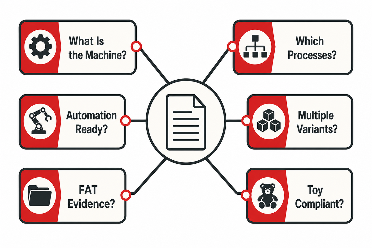
What is a toy assembly machine?
A toy assembly machine is a controlled factory system that feeds, joins, verifies, contains, records, and releases components for a defined toy or product family.
A toy assembly machine receives identified components, establishes their position, performs selected joining operations, verifies agreed process or product conditions, contains uncertain units, and creates production records. It may be a single station or a connected line. The name doesn’t specify one universal design, and it shouldn’t be confused with a consumer construction kit or model that a child assembles.
Which toy assembly processes can be automated?
Common processes such as feeding, orientation, joining, inspection, containment, marking, and data capture may be automated when product evidence and process risk justify the selected method.
Common candidates include part feeding and orientation, screwdriving, press fitting, snap assembly, adhesive dispensing, ultrasonic welding, functional checks, vision inspection, reject handling, labeling, and traceability. Suitability depends on actual materials, geometry, tolerance, cosmetic surfaces, access, defect criteria, and incoming condition. Choose a process from evidence and product risk rather than from a generic equipment list.
How do I know whether a toy is ready for automated assembly?
A toy is ready for automated assembly only when evidence proves feedability, a repeatable datum, a workable joint window, tool access, and inspectability across agreed variation.
Review physical parts from several representative lots and approved alternates. Record delivery state, nesting, static, flexibility, surface sensitivity, pose, locating features, tolerance extremes, tool access, inspection cues, and variant identity. Readiness isn’t a single score. Missing evidence should be assigned to product engineering, supplier quality, process engineering, controls, or quality before it becomes a machine assumption.
Can one toy assembly machine handle multiple variants?
One toy assembly machine may handle multiple variants, but only inside a defined and tested envelope covering components, tooling, recipes, inspection, changeover, release, and controls.
List every change in components, feeders, nests, joining programs, inspection profiles, labels, and data. Identify which transitions are representative and which are boundary cases. Demonstrate line clearance, tooling verification, recipe control, challenge checks, first-piece release, and genealogy. A flexible-machine statement doesn’t prove stable feeding, changeover time, or accepted output for an untested product.
What should a toy assembly machine FAT include?
A toy assembly machine FAT should include agreed samples, operating conditions, functions, failure challenges, records, deviations, decision rules, and named owners for unresolved actions and closure.
A FAT should identify product revisions, lots, software and tooling versions, utilities, staffing, run window, product mix, replenishment, stops, rejects, and interventions. Witness nominal and boundary parts, selected failure reactions, reject containment, recovery, one representative changeover, and record retrieval. State the limits: FAT proves the agreed factory scope, not sustained site capability or all future product compliance.
Does machine acceptance prove that the finished toy is compliant?
No. Machine acceptance and finished-toy compliance are connected but separate evidence layers; product rules, testing, certification, tracking, change control, and release ownership still apply independently.
A machine test can demonstrate specified functions, safeguards, process controls, inspections, reject reactions, and records under stated conditions. Finished-toy compliance depends on the applicable product rules, tests, certification, tracking, change control, and continuing production obligations. Component or station evidence may support that system, but it shouldn’t be presented as a substitute unless the applicable conformity route explicitly permits it.
Keep an evidence map that names which obligation is addressed by the machine, which remains with a laboratory or product-compliance process, and who owns the final release. Revisit that map after a compliance-relevant material, component-source, design, process, or market change. This prevents a valid equipment acceptance result from being reused outside the conditions it actually demonstrated.
How This Guide Was Built
The guide was researched as informational support content beside ZEUEE’s commercial toy assembly solution. Public government, standards, research, patent, and manufacturing-practice sources were used to test product-safety, machinery-safety, readiness, throughput, changeover, and acceptance boundaries. Supplier-specific prices, ROI, rankings, universal sample counts, and unverified performance figures were excluded.
References & Sources
- Toy Safety Business Guidance U.S. Consumer Product Safety Commission
- Safety Standard Mandating ASTM F963 for Toys Federal Register
- ISO 12100:2010 public catalogue ISO
- ISO 13849-1:2023 public catalogue ISO
- Machine guarding and hazardous-energy-control relationship OSHA
- Tolerances and Uncertainty in Robotic Systems NIST
- Assembly Performance Metrics and Test Methods NIST
- Process Stability and Capability NIST/SEMATECH
- Debug, Checkout and Startup ASSEMBLY Magazine
- Toy Safety in the European Union European Commission
- CN108698772B automated toy feeding and assembly architecture Google Patents
WHY WE WRITE THIS
About ZEUEE Engineering Insights
ZEUEE shares technical guides based on real automation project experience. Since 2005, we have designed and manufactured non-standard automation equipment for connector assembly, wire harness production, robotic lines, vision inspection, and smart factory upgrades.
Founded in 2005
20,000 m² production base
120+ specialists
150+ R&D patents
ISO9001:2015 certified
![Automated Screwdriving: Torque & Cycle Time [Guide]](https://zeueeauto.com/wp-content/uploads/2026/10/automated-screwdriving-featured-768x512.png)
![Automated Screwdriving: Torque & Cycle Time [Guide]](https://zeueeauto.com/wp-content/uploads/2026/10/automated-screwdriving-featured-150x150.png)