Get in touch with Zeyu lntelligent Industrial Company

Brush Assembly Machine Guide: Process, Quality, and FAT

Updated October 2026 · Written by Cherry
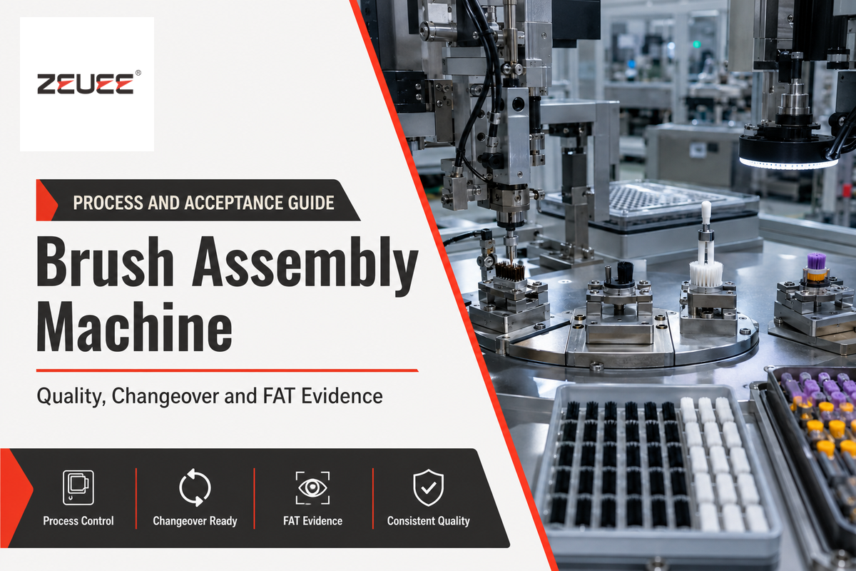
A brush assembly machine is automatic equipment that joins and verifies already manufactured brush components. Depending on the product, inputs may include a handle, ferrule, bristle bundle, cap, spring, wire, holder, housing, or preformed brush head. Drilling holes, tufting filament, bristle cutting, and producing a complete brush line remain separate process scopes unless the project explicitly includes them.
That boundary is important since the search term could mean carbon and motor brushes, cosmetic or paint brushes, brushes used in household products, or industrial brushes, and equipment used to manufacture brushes. Thus, the same search term can describe very different incoming parts, joining methods, inspections and acceptance tests.
Broader brush machinery can include automatic drilling, tufting, cutting, trimming, adhesive filling, metal ferrule forming, steel spring handling, and pack-out. Drive or transmission design belongs to machine configuration after the product process is fixed. ZEUEE groups adjacent equipment under its automated assembly machines hub; this guide continues to separate operations by evidence.
Quick answer
Plan a brush assembly machine by defining the incoming components and released product first. Then prove part feedability, fixture control, joining evidence, defect containment, qualified output, variant changeover, maintenance access, traceability, and FAT challenges. Searches for a brush assembly machine for sale, an industrial brush assembly machine, or a manual brush assembly machine often mix procurement with process questions; configuration, price, published performance, and quotation belong to the commercial solution page after this engineering scope is clear.
Quick planning map
| Scope basis | Named incoming components, included operations, and released product state |
|---|---|
| Readiness basis | Controlled presentation, orientation, variation, surface, and damage evidence |
| Quality basis | Characteristic, method, reaction, record, and release owner |
| Output basis | Qualified good units under a stated product mix and time window |
| Acceptance basis | Agreed samples, failures, recovery, records, limits, and signatures |
1. What Does a Brush Assembly Machine Actually Assemble?

The first requirement needs to be “The machine accepts these controlled components, performs these functions, and releases the product in this state.” If that isn’t the case, then selection of the station has occurred too early. This scope statement becomes the basis for every later test and release decision.
Motor-brush projects may load a carbon element, conductor, spring, terminal, and holder. A paintbrush project may involve joining a prepared bristle head to a ferrule, a handle and an adhesive or fastener. A household product project may involve joining a molded body to a cap and a brush element. Each project creates different feeding, fixturing, joining and inspection problems.
Tufting is narrower: filament is inserted or anchored in a prepared body. Drilling forms receiving holes. Trimming gives the bristle field its final profile. On a complete brush-making line, these operations may be coupled with downstream component assembly, but the evidence for each operation should remain distinct. Good tuft formation does not prove that the handle, ferrule, electrical lead, or finished pack was assembled correctly.
Brush making operations
- Filament preparation
- Drilling and tufting
- Trimming or finishing
- Brush-block or head production
Brush assembly operations
- Component identification and feeding
- Orientation and fixturing
- Pressing, crimping, staking, fastening, or bonding
- Inspection, containment, marking, and release
A 2025 patent publication discloses a slip-ring brush assembly device with two robotic arms and dedicated material-conveying elements. The publication illustrates a robotic system that may convey and assemble individual wires. It is a good reference for a product-specific brush assembly architecture. The patent shouldn’t be construed to provide evidence of the commercial capability or suitability of the brush assembly device for a family of brushes outside the scope of the patent.
2. Which Product Inputs Must Be Stable Before Automation?
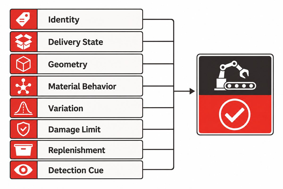
A final product drawing may not be sufficient for automation. Consider how a feeder experiences each part before the customer sees the finished brush. Parts may separate, nest, flex, rotate, slide, collect dust, carry static, show flash, or receive cosmetic damage. For design and automation, focus on the functional details of a product rather than heuristics.
Use an 8-Row Feedability Matrix to connect the drawing to the delivery state. For the matrix, use approved alternates and boundary samples. The goal is to find variations that are harmless to product function but disruptive to automated presentation.
| Input category | Evidence to collect | Failure question | Owner |
|---|---|---|---|
| Identity | Part number, revision, lot, approved alternate | Can the wrong revision enter the cell? | Product and quality |
| Delivery state | Tray, bag, bulk, reel, bundle, separator, protective film | Does unpacking change orientation or damage risk? | Supply chain and operations |
| Geometry | Critical interfaces, symmetry, center of mass, flash, burrs | Can the part be presented in more than one stable pose? | Product and tooling |
| Material behavior | Flexibility, friction, static, oil, dust, magnetic response | Will parts tangle, cling, bridge, or mark? | Process engineering |
| Variation | Multiple lots, cavity differences, approved extremes | Was the feeder trial built around only an easy lot? | Quality and supplier quality |
| Damage limit | Cosmetic zones, bend limits, contamination rules | Can the feeding method create an accepted-looking defect? | Product and quality |
| Replenishment | Refill quantity, operator access, low-level signal, material segregation | Can a refill disturb flow or mix lots? | Operations and controls |
| Detection cue | Features available to sensors, vision, gauges, and fixtures | Can the system distinguish presence, identity, pose, and seating? | Controls and quality |
The University of New Mexico teaching handout on design for manufacturing summarizes heuristics such as minimizing handling and assembly directions, using symmetry deliberately, and adding guiding features where practical. Treat these as design prompts rather than a current standard; they do not establish a universal feeder or orientation threshold.
3. How Does the Process Move From Feeding to Release?
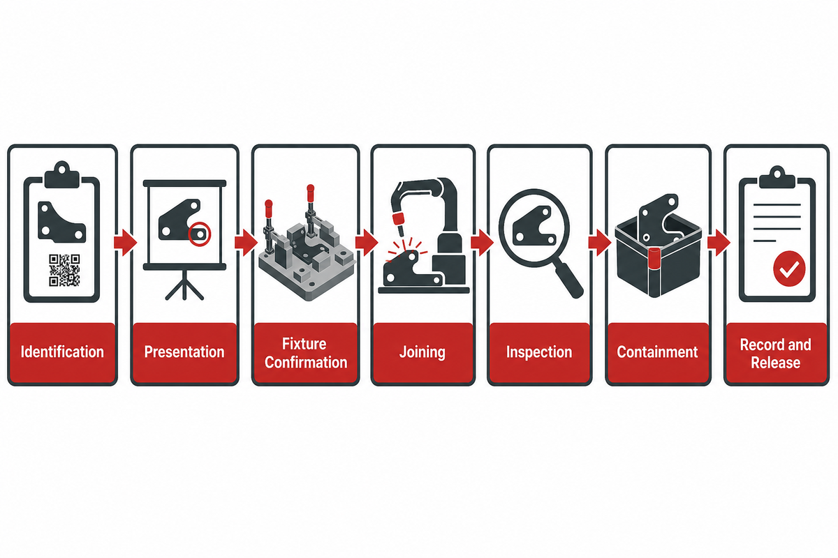
With feedability and input variation defined, standard work for brush assembly follows repeatable process logic even when the hardware varies. Identifying the parts, separating the parts, establishing part orientation, ensuring the state of the fixture, performing the joint, checking out the agreed characteristics, containing defects, marking or recording the result, and releasing the part to next operation are the repeating steps.
Each step of a process should have an entry and exit condition. For example, just because a part is present doesn’t mean it’s the correct part in the correct orientation. A press stroke doesn’t mean the joint was accepted. A camera result doesn’t mean the unit was released. Reject routing and record association should be confirmed before releasing the unit.
- Start with Identification: bind work order, product revision, material lots, and the approved recipe.
- Presentation: singulate components and preserve the required orientation without unacceptable damage.
- Fixture confirmation: verify tooling, nest state, part presence, seating, and any safety interlock needed for the next action.
- Joining: control the selected press, crimp, stake, weld, fasten, or bonding process.
- Inspection: check characteristics that the sensor, camera, gauge, or tester is designed to measure.
- Containment: divert failed or uncertain units and define the suspect population after a drift, jam, or interruption.
- Record and release: join the unit or lot to process, inspection, rework, and authorization evidence.
Manual assists and buffers should be shown in the process map. An operator who removes jams, cleans sensors, clears chutes, or aids in part alignment changes staffing, cycle time, risk, and traceability. A controlled manual assist should be shown in the process. An unaccounted for assist breaks the design and acceptance evidence. When those dependencies span several stations, ZEUEE’s production line automation overview provides adjacent system context.
NIST’s Assembly Performance Metrics and Test Methods work focuses on task performance. Prior to defining the pass number, define the task and method to be performed.
4. How Does the Joining Method Change the Control Plan?
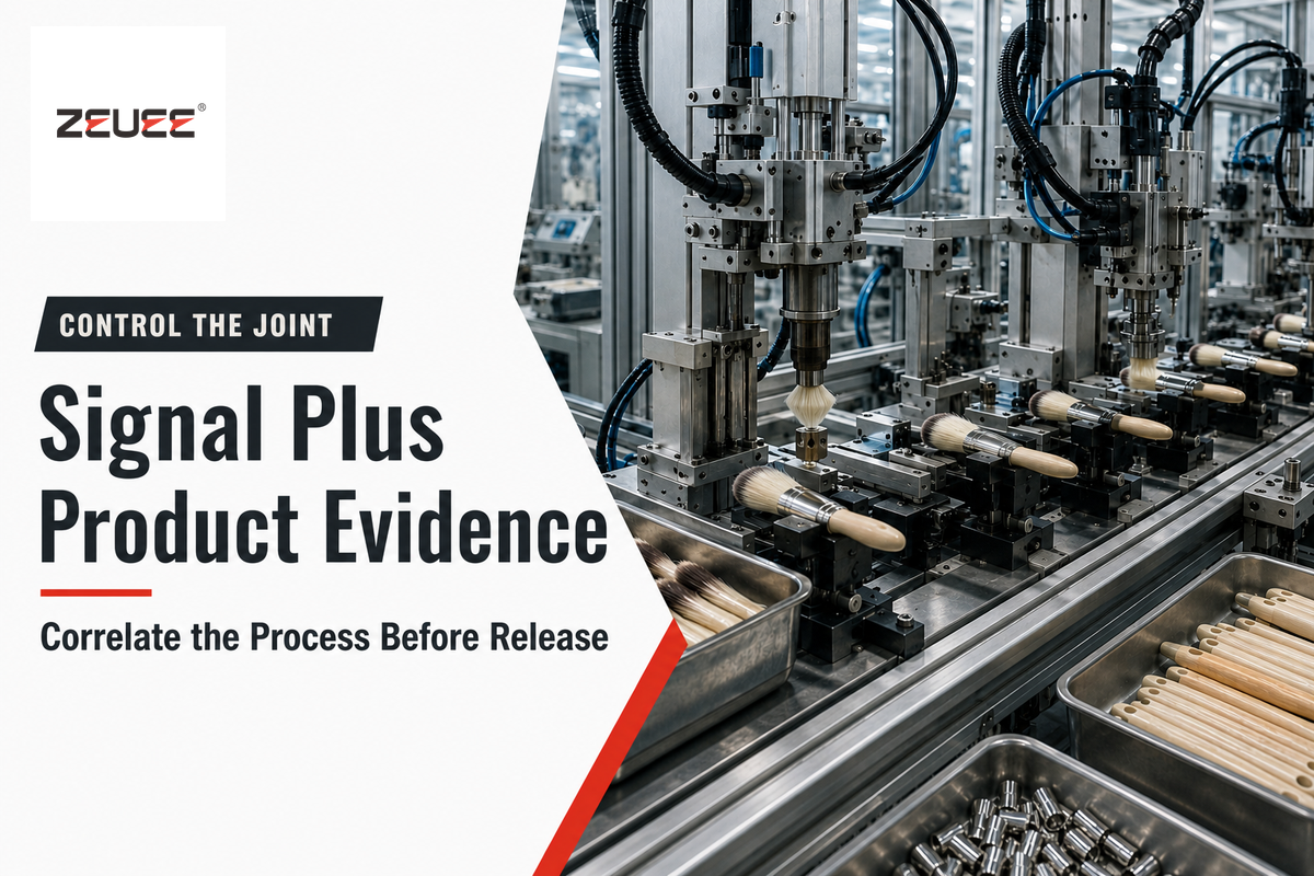
After process handoffs are defined, the joining method determines which inputs matter, which process signals are meaningful, and which product checks remain necessary. Press fits may monitor force and displacement. Crimps may require tool and joint-geometry evidence. Adhesive bonding adds material identity, dispense, open time, cure, and surface preparation. Welding adds energy, tooling, contact, and heat effects. Screw joints add fastener identity, torque-angle behavior, and retention rules.
| Method | Typical process evidence | Product question still open |
|---|---|---|
| Press fit | Force-displacement trace, end position, fixture state | Does the trace correlate with seating and retention for this design? |
| Crimp or stake | Tool identity, setting, stroke, monitored signature | Are geometry and strength acceptable across material variation? |
| Adhesive | Material lot, dispense confirmation, time and cure state | Are wetting, bond area, cure, and finished strength verified? |
| Weld | Program, energy or current signature, tooling and clamp state | Does the signal correlate with the required joint integrity? |
| Fastener | Fastener identity, torque-angle or depth result | Are engagement, seating, retention, and surface limits satisfied? |
ASSEMBLY’s force and displacement monitoring example shows what can be captured during a press event. It doesn’t supply brush-specific limits or prove that one signature detects every hidden or long-term failure.
Correlation should be planned. Compare process signals to dimensional, functional, destructive, or life evidence where it’s required. Freeze the fixture, sensor, sampling, measurement method, and retest rule. A process monitor becomes useful when a failed signal leads to a defined containment and release decision.
5. Where Do Brush Assembly Defects Escape?
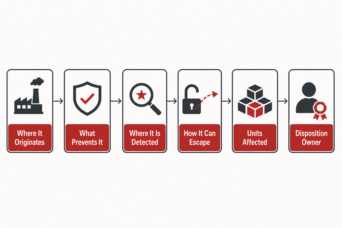
A defect list is just a starting point. The Defect-to-Station Diagnostic Tree asks where a defect originates, what prevents it, where it’s detected, how it can escape, what units are affected, and who makes the final decision on disposition. This turns quality control into a documented containment and release system.
| Defect family | Likely origin | Evidence and reaction | Escape risk |
|---|---|---|---|
| Missing, doubled, or mixed part | Replenishment, feeder, pick, or line clearance | Identity and presence check; stop, reject, and reconcile suspect material | A presence sensor may not distinguish revisions |
| Reversed or misoriented part | Singulation, orientation, robot frame, or nest | Pose confirmation and controlled reject | Symmetrical appearance may hide functional orientation |
| Under-seated or over-driven joint | Component variation, fixture, program, or joining tool | Position or process signature plus product verification | A final image may not reveal hidden joint state |
| Weak bond or crimp | Material, surface, tooling, dispense, cure, or process drift | Process record and planned strength evidence; contain since last known good | Electrical or visual pass may coexist with weak retention |
| Cosmetic damage or contamination | Bulk handling, fixtures, adhesive, cleaning, or downstream transfer | Defined visual zones, lighting, samples, and disposition | Different surfaces need different inspection conditions |
| Traceability mismatch | Recipe, printer, scanner, rework, or database join | Forward and reverse record check; hold release | Correct data stored under the wrong unit is still a failure |
The key containment question is “since when?” A reject at the camera tells the team about one observed unit. If the cause may have existed earlier, the line needs a last-known-good point, a suspect window, physical and/or electronic holds, and a release owner.
Machine vision is good for characteristics that are apparent under its field of view, optics, lighting, fixtures, and rules. It cannot recover information that the process never made visible. Additional images may not create traceability unless the result is associated with product identity, material, recipe, rework, and/or release. For broader test-station context, review ZEUEE’s automated testing equipment; the selected method still has to match the brush risk and release rule.
6. Why Is Qualified Output Lower Than a Headline Cycle Rate?
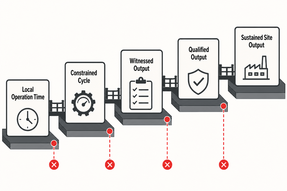
Defect containment and release decisions explain why one station’s motion time is not finished output. The Qualified Output Loss Bridge starts with the constrained cycle, and makes availability, replenishment, minor stops, rejects, reinspection, approved rework, changeover, cleaning, and blocking downstream, visible. This distinction supports a business case built on qualified output instead of one nominal motion.
The planning relationship is:
Qualified output = scheduled time ÷ constrained effective cycle × availability × first-pass yield
Define every term for the agreed product mix and window. Don’t use this relationship as a supplier performance guarantee.
The Lean Enterprise Institute includes load/unload and allocated changeover in effective machine cycle time. For a brush project, also ask whether the figure includes bowl replenishment, adhesive refill, sensor cleaning, planned sampling, label roll changes, blocked discharge, or the first-off approval after a recipe change.
Compare five clearly labeled numbers:
- Local operation time: one press, dispense, weld, camera, or robot action.
- Constrained cycle: the slowest required qualified handoff for the current product and sequence.
- Witnessed output: what ran during a stated FAT condition.
- Qualified output: accepted units after the agreed reject and rework rules.
- Sustained site output: production evidence collected after installation under intended staffing, material, utilities, and maintenance conditions.
Longer nominal runs are useful, but they do not automatically test more requirements. Deliberate variation of part lots, changeover plans, safe jam recovery scenarios, and record retrieval may reveal more than the easiest unit.
7. How Should Variant Changeover Be Released?
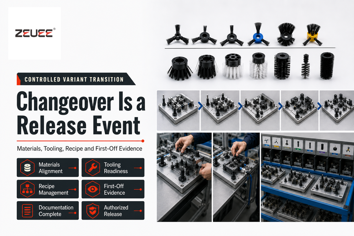
Because changeover consumes part of the available production window, a brush variant can change the incoming part, feeder tooling, nest, joining program, adhesive or fastener, camera profile, tester limits, label data, pack instruction, and traceability fields. Mixed-model production therefore needs a release rule for each approved transition.
Use a Changeover Release Runbook:
- Close the previous order and record the last accepted unit.
- Reconcile and remove previous materials, labels, and work in process.
- Apply the required hazardous-energy controls before exposed setup or tool work.
- Install and verify feeders, guides, nests, tools, sensors, and change parts.
- Load the approved recipe, inspection profile, limits, and label data.
- Run challenge parts or inspection checks defined for the new variant.
- Produce first-off units and review every required record.
- Authorize normal production with a named owner.
Quality release and safety release are different. Under the general-industry conditions mentioned in the United States (U.S.), OSHA 1910.147, activities such as adjusting, setup, cleaning, unjamming, and tool changes while servicing or maintaining equipment are covered if unexpected energization or release of stored energy can injure employees. First good piece approval doesn’t replace control of hazardous energy.
Note the duration of the observed changeover, as well as the definitions of the start and end states, the individuals involved, the product pair, the scope and type of tooling involved, safety steps, first off piece, and outstanding concerns. One observed changeover doesn’t provide evidence for all possible changeover pairs.
8. What Should a Brush Assembly Machine FAT Prove?
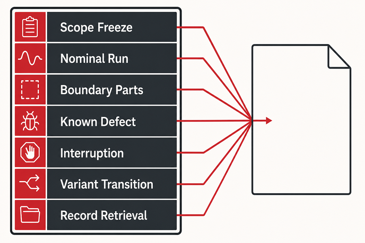
The factory acceptance test should prove the agreed factory scope under documented conditions; it does not certify every future material lot, operator decision, site utility, maintenance action, or variant. It should also show how the cell reacts to selected defects, interruptions, and representative variant transitions.
That changeover boundary carries directly into the Witnessed Failure Challenge, which requires more than a nominal demonstration.
| Challenge | Evidence | Limit |
|---|---|---|
| Scope freeze | Approved revisions, samples, assumptions, methods, and owners | Does not cover undocumented changes |
| Nominal run | Time basis, product mix, accepted units, stops, rejects, and interventions | Does not prove sustained site capacity |
| Boundary parts | Named lot, geometry, presentation, or cosmetic conditions | Only the agreed boundary is tested |
| Known defect | Safe challenge, expected detection, reject route, and record | Only the challenged failure mode is covered |
| Interruption | Stop, held units, recovery, restart, and authority | Factory utilities and site utilities may differ |
| Variant transition | Line clearance, change parts, recipe, checks, first-off, and release | One pair does not represent all variants |
| Record retrieval | Forward and reverse links across material, process, inspection, rework, and release | Retention and system integration remain project-specific |
A 2017 ISA InTech article on FAT, republished by Automation.com, describes its role in checking hardware and software against specifications before startup. It’s dated practical commentary rather than a universal machine standard. Build the protocol from the contract, product risks, applicable requirements, and agreed responsibilities.
Separate FAT from site acceptance, capability studies, and ramp release. Capability studies require sufficient evidence over time, and site acceptance assesses installed interfaces and conditions.
Machine safety requires its own body of evidence. The official ISO 12100:2010 page identifies the current confirmed edition and its general machinery risk-assessment and risk-reduction scope. The public page is an abstract; the project must use the complete applicable requirements and rightful safety ownership.
9. What Belongs in the Technical Handover Brief?
The technical handover should allow an integrator or machine manufacturer to test assumptions before suggesting a configuration. Treat the brief as a controlled tech-transfer record: give controlled evidence, label open questions, identify each decision maker, and separate verified facts from assumptions.
Handover brief fields
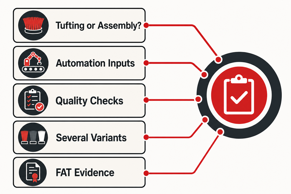
- Incoming components, included operations, released state, and responsibility boundary
- Product drawings, revisions, representative and boundary samples, and approved alternates
- Delivery states, orientation cues, feed trials, surfaces, variation, and damage rules
- Joining methods, critical characteristics, process signals, product tests, and reaction plans
- Variant family, change parts, recipes, inspection profiles, labels, and first-off release
- Qualified-output definition, product mix, operating window, replenishment, rejects, and rework
- Traceability keys, data fields, containment, rework, retrieval, retention, and interfaces
- Facility, utilities, guarding, hazardous energy, maintenance access, and responsible parties
- FAT samples, methods, limits, challenge faults, evidence format, open issues, and signatures
After the scope is controlled, review ZEUEE’s brush assembly machine solution for application specific configuration and commercial discussion. That page owns machine options, published specifications, compatibility, pricing, quotation and RFQ. Keeping that handover late protects the informational role of this guide.
The About ZEUEE page provides first party company context. Technical information on this guide is limited to the public sources and scope listed below.
Key takeaway
A defensible brush assembly project defines feedable inputs, controlled joints, visible failure reactions, qualified output, safe changeover, and witnessed acceptance before it asks for a machine configuration.
Review a Defined Brush Assembly Scope
Brush Assembly Machine FAQ
Is a brush assembly machine the same as a brush tufting machine?
Not necessarily. Tufting inserts filament; assembly joins defined components into a released product. The correct label depends on the incoming part, included operation, and released product state.
A tufting machine inserts or anchors filament in a prepared brush body. A brush assembly machine may instead join a handle, ferrule, preformed head, spring, wire, holder, cap, or housing. Some lines combine drilling, tufting, trimming, assembly, inspection, and packing. The requirement should name the incoming parts, included operations, and outgoing product state rather than rely on the equipment label.
What information is needed before automating brush assembly?
Prepare controlled product, part-presentation, process, quality, variant, data, safety, and acceptance evidence before a station, tooling concept, operating rate, or layout is selected and quoted.
Start with product drawings and revisions, physical samples, component delivery states, approved joining methods, known defects, acceptance tests, target variants, demand, traceability, and facility interfaces. Add evidence about orientation, nesting, flexibility, contamination, surface sensitivity, lot variation, and damage limits. That package lets the team test feedability and fixturing assumptions before it commits to stations or an output figure.
How should brush assembly quality be checked?
Match each product risk to a suitable process signal, product check, failure reaction, record, and release owner. Tie every result to containment and release authority.
Presence and orientation may suit sensors or vision. Joint formation may need force, displacement, energy, torque, dispense, or cure evidence plus dimensional, functional, electrical, retention, or destructive checks where applicable. The plan must define what happens after failure, which units are suspect, whether retest is allowed, and who can release them. No single camera or process curve proves every hidden or long-term characteristic.
Can one machine handle several brush variants?
Potentially, when the contracted variant envelope and release work are explicit. Evidence must cover actual parts, tooling, recipes, inspections, data records, and representative changeovers before release.
Define changes in parts, presentation, tooling, recipes, joining programs, inspections, labels, and data. Demonstrate representative transitions with the actual sample set. A statement that a line is flexible doesn’t establish feeding stability, changeover time, or first-off quality for an untested family.
What should be included in brush assembly machine FAT?
Include the agreed revisions, samples, output basis, defect challenges, containment, recovery, records, documentation, and owners. Record the test conditions and remaining site-specific limitations explicitly before approval.
Witness nominal and boundary parts, one representative changeover, selected failure reactions, reject containment, stop and restart behavior, genealogy retrieval, documentation, training, and applicable safety checks. Record the conditions and open issues. FAT demonstrates the agreed factory scope; it doesn’t replace site acceptance, long-run capability, maintenance qualification, or ramp monitoring; the underlying acceptance-test context is documented at https://www.automation.com/article/bypassing-factory-acceptance-test-startup-bad-idea.
The protocol should name the sample source, revision, lot, delivery state, run window, staffing, replenishment method, utilities, software version, tooling, inspection method, and data file. For each challenged failure, record whether the line stops, rejects, alarms, protects the suspect population, and recovers without losing genealogy. List deviations beside an owner and due date, then distinguish factory closure evidence from items that must wait for the installed site. This prevents a smooth demonstration from being mistaken for proof under conditions that were never witnessed.
The Final Engineering Rule
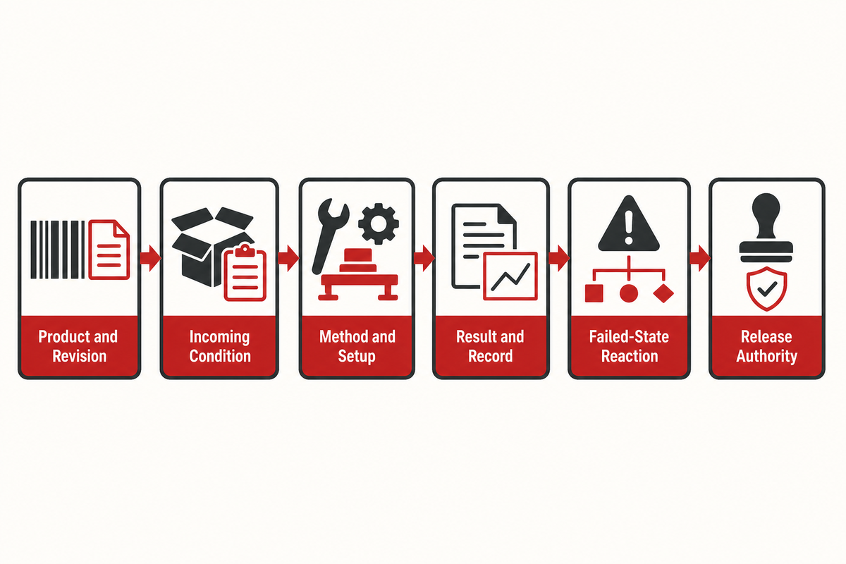
Judge a brush assembly machine as a controlled path from approved component state to released product evidence. For every important claim, ask: which product and revision, which incoming condition, which method and setup, which result and record, which failed-state reaction, and which role had authority to release it?
These questions keep the engineering guide useful without duplicating the solution page. They also turn a machine demonstration into a production system decision.
Research Method for This Guide
This article was researched as informational support content beside ZEUEE’s commercial brush assembly solution. The process, measurement, safety, cycle-time, and acceptance claims were checked against current public government, standards, university, research, patent, and automation trade sources. Supplier-specific prices, rankings, ROI, configurations, and universal performance claims were excluded. Reviewed by the Shenzhen Zeyu Intelligent Industrial Science Technology Co., Ltd technical team.
References & Sources
- ISO 12100:2010 public catalogue ISO
- 29 CFR 1910.147: Control of hazardous energy OSHA
- Assembly Performance Metrics and Test Methods NIST
- Tools for Robotics in SME Workcells NIST
- Design for Manufacturing Guidelines University of New Mexico
- Tips for Tooling Feeder Bowls ASSEMBLY
- Force and displacement monitoring during press-fit assembly ASSEMBLY
- Cycle Time Lean Enterprise Institute
- Recommended Calibration Interval NIST
- Why Bypassing the Factory Acceptance Test Is a Bad Idea Automation.com / ISA-origin article
- CN120955438A brush-wire assembly device Google Patents
WHY WE WRITE THIS
About ZEUEE Engineering Insights
ZEUEE shares technical guides based on real automation project experience. Since 2005, we have designed and manufactured non-standard automation equipment for connector assembly, wire harness production, robotic lines, vision inspection, and smart factory upgrades.
Founded in 2005
20,000 m² production base
120+ specialists
150+ R&D patents
ISO9001:2015 certified
![Automated Screwdriving: Torque & Cycle Time [Guide]](https://zeueeauto.com/wp-content/uploads/2026/10/automated-screwdriving-featured-768x512.png)