Get in touch with Zeyu lntelligent Industrial Company

Crimp Force Monitoring: Prove Defect Coverage Before Purchase

Updated October 2026
Crimp force monitoring compares the force signal from each press stroke to a qualified reference. A passing curve tells you that the measured process stayed within its limits. It doesn’t prove that each strand was in the process, or that the finished connection meets all of the electrical requirements.
Quick specification check
- Identify the terminal, wire, applicator, press and sensor together.
- Request force versus time or position, with the analysis zones identified.
- Keep good-part rejection separate from missed challenge defects.
- Include the physical reject route and recipe-change responsibilities in the offer.
Crimp force monitoring is a process check qualified for a particular connection. Before purchase, test verified good parts, known defects and reject handling separately. Keep the customer’s specified joint inspections in the control plan.
A buyer has to have evidence that survives the journey from a supplier demo to the installed equipment. Start with the smallest defect that impacts your product. Then, verify that the sensing, software, and manufacturing processes can detect and distinguish the defect from acceptable variations.
- Monitoring every stroke doesn’t mean detecting every defect.
- A verified reference comes before teach-in; a smooth curve alone is insufficient.
- Correct detection still needs a working stop or reject mechanism.
- Sample counts and acceptance limits must be agreed before the trial.
What crimp force monitoring measures
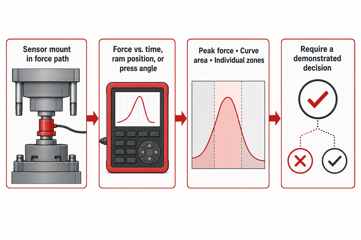
A crimp force monitor measures a process signal during the working stroke and compares selected features to a reference curve. Depending on the equipment, analysis may be force vs. time, ram position, or press angle. Peak force, curve area, and individual zones address different aspects of a process in a changing state.
The basic measurement starts with a suitable sensor mount in the path of press force. One approach to this is to use piezoelectric force sensing, but, by itself, this doesn’t indicate defect coverage. The manufacturer should point out the measured axis, trigger, filtering and evaluated portion of the stroke. A display labelled “force” needs to show units and describe any scaling.
Rob Boyd’s technical explanation in Assembly covers reference based monitoring and application-dependent settings. Use that distinction when reviewing a benchtop retrofit or a new machine; a peak-only readout and analysis of several curve zones aren’t the same.
Standalone press retrofit
- Check sensor mounting and stroke compatibility.
- Agree the operator stop and restart sequence.
- Assign data export to a named supplier.
Integrated assembly line
- Include automation feed and transfer conditions in the trial.
- Track the detected part to its reject location.
- Assign control and traceability integration.
A typical purchase error is treating a force display as the whole inspection function. Require the supplier to demonstrate which feature changed for your challenge sample and how that change caused the recorded decision. Absence of such a demonstration indicates that detection remains unproven.
Which defects can a crimp force monitor detect?
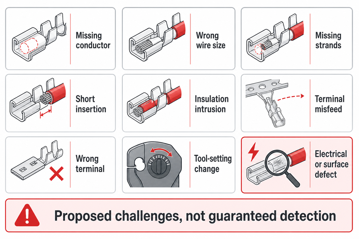
Missing wires or strands and insulation within the conductor crimp can modify a force signature; their detectability will depend on the connection and normal process variation. Each required fault should be qualified separately. The supplier’s defect list provides a basis for testing. Whether a given bad crimp can be reliably separated still needs to be demonstrated.
Terminal forming force may obscure the remaining force contribution from the conductor. A fault that gives a clear signal on one terminal may exist in the good-part distribution on the other terminal. The nine checks below turn this limitation into a sample request. They’re proposed challenge types; some require an additional inspection function.
| Fault family | Challenge to prepare | Independent evidence | Limitations / Not suitable for |
|---|---|---|---|
| Missing conductor | Terminal formed without the intended wire | Recorded sample identity and visual confirmation | Does not establish sensitivity to one missing strand |
| Wrong wire size | A plausible incorrect conductor from the actual product mix | Wire part number and cross-section in mm² | Similar signatures can overlap; size alone is not identity |
| Missing strands | Defined strand loss, starting with the smallest relevant fault | Count removed strands and record preparation | Terminal forming force can mask conductor loss |
| Short insertion | Measured insertion deficit at the conductor crimp | Insertion position in mm; section or image where needed | Similar force need not imply proper conductor position |
| Insulation intrusion | Controlled insulation position within the conductor barrel | Strip length and location record | Severity and insulation material affect separation |
| Terminal misfeed | A safely prepared representative feed error | Position image and feeder state | Do not risk tooling damage merely to create a sample |
| Wrong terminal | A plausible mixed terminal, where safely testable | Terminal part number and lot | Some mix-ups need identification or vision checks |
| Tool-setting change | An agreed controlled change to the approved setup | Setting record and measured crimp height | Force does not directly measure every final dimension |
| Electrical or surface defect | Application-relevant contact or surface condition | Specified electrical, visual or environmental test | A mechanically similar defect may be invisible to force |
The basis for the table is the synthesis of application limits described by Gustavo Garcia-Cota in ConnectorSupplier and the measured fault classes described in the research below. The table isn’t a validated ZEUEE detection specification.
Let’s say a buyer’s critical defect is one missing strand. A supplier shows a big change by mostly removing the conductor. That’s a demonstration of separation for the prepared sample only. Ask for the smaller fault, define and verify how it occurs, and compare it to natural variation of a good part. If the curves overlap, ask for a complementary check or a different process design. Widening or narrowing a tolerance cannot create measurement information that the setup does not provide.
In Hofmann and colleagues’ 2026 case study, 1,617 curves came from two pairings using 0.50 mm² and 0.35 mm² conductors. Reported overall accuracy was 95.9% but, of the 163 defective test samples, four were classified as OK. The authors wrote that the four test samples were only slightly manipulated toward the defective state. Those results belong to that study, not to ZEUEE or every commercial monitor.
Crimp force monitoring vs height and pull testing
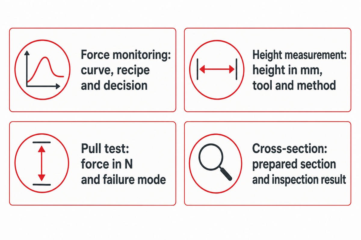
For cable assembly tests, monitoring, dimensional checks and destructive tests supply different evidence. A manufacturing quality control plan should incorporate the requirements of the terminal specification and customer agreement. Monitor qualification can help develop that plan, but a curve passing its tolerance limits doesn’t, in and of itself, authorize removal of a specified pull test and/or dimensional inspection.
What is the difference between crimp height and pull force testing?
Crimp height measures a finished dimension, normally recorded in millimetres, against the applicable terminal requirement. Pull testing measures retention under a defined procedure, typically in newtons. Neither of these results describes every internal feature of the joint. Force monitoring provides a record of the forming process; the three methods address related but different quality questions.
| Method | Record | Question still open |
|---|---|---|
| Force monitoring | Curve, recipe and decision | Finished geometry and electrical suitability |
| Height measurement | Height in mm, tool and method | All internal strand distribution |
| Pull test | Force in N and failure mode | Every production part and long-term contact behaviour |
| Cross-section | Prepared section and inspection result | Unsectioned parts and service exposure |
Terry Curtis’s Assembly article gives the reasons for combining process capability and finished joint checks. For a broader choice of presses and manual equipment, see the connector crimping machine selection guide.
Don’t consider a borderline result or height as absolute ground truth. Agree the measuring method, instrument suitability, and disposition of samples in ambiguous cases. NIST’s measurement-uncertainty guidance explains why repeatability, time variation, and bias are to be considered. Applying this principle means settling uncertain cases first before evaluating the monitor.
NASA’s review of 780 pull-test results discusses possible reductions in test frequency only with verified conditions and project risk assessment. A purchasing team should get the required agreement for a revision of the plan instead of assuming monitor installation is approval to revise the plan.
Electrical and environmental qualification remain separate. The public scope of IEC 60352-2:2024 includes stranded conductors from 0.05 to 10 mm² and solid-wire diameters from 0.25 to 3.6 mm, within its stated connection types. It excludes coaxial cable crimps. Those are standard scope boundaries, not force-monitor detection limits.
Build a reference that survives production variation
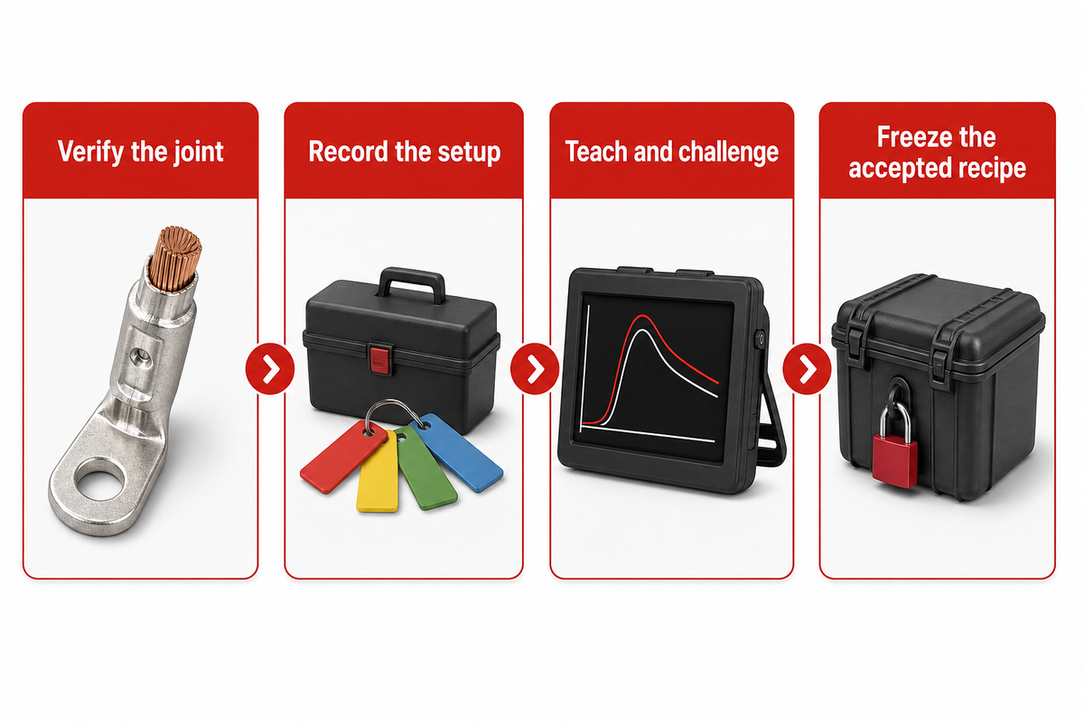
A useful starting point is independently accepted crimps made under controlled conditions. Retain the identity of the wire and terminals, and the tool settings and state with the curve. Then, test production variation against this. Teaching an attractive waveform from an unverified joint can give the false impression that an improper process is acceptable.
“simply plugging in a CFM will not solve all their crimp quality issues.”
The article identifies some differences of material and preparation that can influence the force signature. For terminals of different hardnesses and different thickness, as well as for different conditions of the wire, the monitor would be influenced by their combined effect. A reference from a favorable production batch still needs a trial against the variation expected in the purchased application.
- Verify the joint. Apply the agreed dimensional and destructive checks before teaching.
- Record the setup. Save part numbers, material lots, crimp applicator identity, press settings and sensor installation.
- Teach and challenge. Use the supplier’s procedure, then run the agreed good and defective samples.
- Freeze the accepted recipe. Record software version, limits and authorization for later changes.
We assume a hypothetical case of a line changing from a 0.35 mm² product to a 0.50 mm² product. Reusing the previous recipe leaves the acceptance basis unresolved. Engineering should verify the complete terminal and conductor pairing, and not only the nominal cross section. A replacement applicator can make another difference even if the wire size remains at 0.50 mm². The setup record of the monitor would capture those differences prior to the production operator being asked to “teach again.”
For a 0.35 mm² application, a good reference belongs to a documented terminal, conductor and tooling combination. An increase to 0.50 mm² is a clear review trigger, not a universal directive to copy or widen the old limits. The buyer should require a controlled recipe release for the changed combination.
Run the 3-Lane Crimp Acceptance Trial before purchase
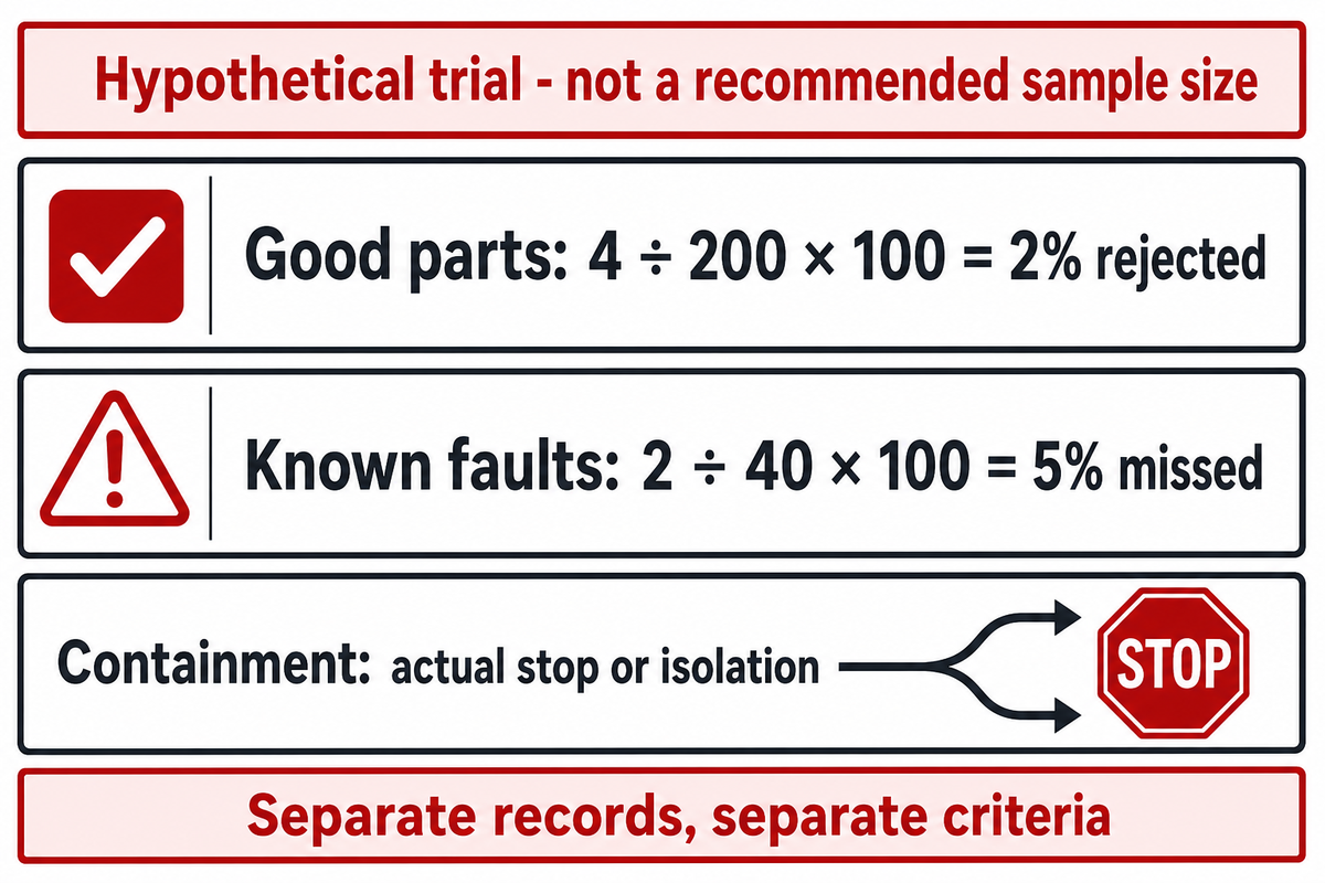
The 3-Lane Crimp Acceptance Trial organizes accepted parts, defined fault samples and physical containment checks into three records. This record structure indicates supplier evidence; it isn’t a validated sampling standard. Agree upon performance requirements and a justified sampling plan before running the trial; then assess each lane against its stated requirement.
3-Lane Crimp Acceptance Trial
A buyer’s recording framework that separates good-part rejection, known-fault misses and the line’s handling of detected parts.
Before testing, agree upon the smallest relevant fault, good-part rejection, required detection performance and risk of a wrong acceptance decision. Also agree sample selection, sample size, independent labels and who adjudicates borderline results. The public abstract of NIST Technical Note 2045 relates performance requirements, sample sizes and decision risk; it doesn’t prescribe a crimp trial count.
| Lane | Input | Record and decision |
|---|---|---|
| Good parts | Independently accepted samples covering agreed normal variation | Rejected good samples / good samples tested; compare with the agreed criterion |
| Known faults | Identified fault type and severity, separated by application | Missed samples / samples challenged, separately for each fault |
| Containment | A detected part followed through the installed line sequence | Actual stop or isolation, part identity and controlled restart |
The hypothetical trial contains 200 independently accepted pieces and 40 pieces with one defined fault severity. Four good pieces are rejected, so the observed good-part rejection is 4 ÷ 200 × 100 = 2%. Two challenged defects pass, so the observed miss proportion for that challenge set is 2 ÷ 40 × 100 = 5%. Both counts should be reported. One combined accuracy figure wouldn’t be acceptable. Nor would calling either percentage a “guaranteed production rate” be acceptable.
Artificially seeded faults don’t correspond to the natural frequency or severity of production defects. NIST’s discussion of production defect proportions begins with random sampling from a process or population. In the context of this trial, that means the miss proportion of a challenge set can’t be presented as the outgoing defective proportion of the factory.
How to check if a crimp is good?
A good-crimp decision follows the applicable terminal specification and customer control plan. Determine if a sample conforms by checking the required dimensions and workmanship and performing the specified retention or section tests. If the result is uncertain, resolve the uncertainty before making a final decision. During monitor qualification check if the displayed decision agrees with the force trace and physical outcome.
Use a sample ID to track results and decisions. On a multi-station line, test what happens when an alarm occurs just before a sample is transferred. A correct decision isn’t sufficient if the good part container receives the sample that was supposed to be rejected.
A 2% good part rejection rate and a 5% miss rate in the hypothetical case study describe different problems and different denominators. Merely being small won’t make either acceptable. The decision is dictated by previously agreed upon criteria and sampling strategy and is captured in the worksheet.
Control nuisance rejects and recipe changes
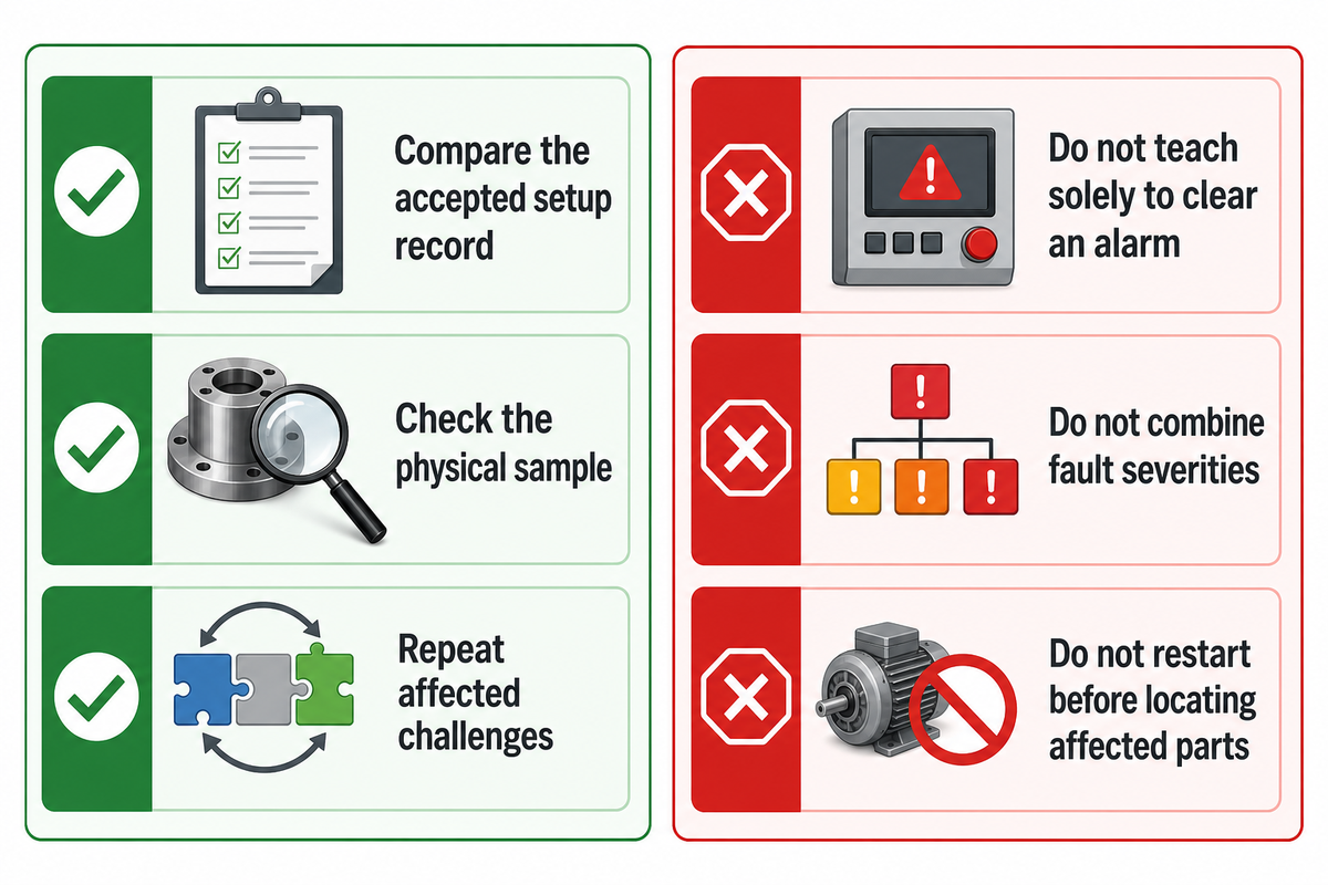
Nuisance rejects in terminal crimping require a deeper process review before implementing tolerance changes. Check sample ID, material lots, wire prep, tooling condition and sensor installation against the accepted setup. Save the rejected crimp curves with the independently checked sample outcomes. Wider limits may reduce alarms, but may also admit faults the monitor was purchased to catch.
Do
- Compare the alarm with the accepted setup record.
- Check the physical sample before changing its label.
- Repeat affected challenges after an approved adjustment.
Don’t
- Teach a fresh reference solely to clear an alarm.
- Mix different fault severities in one miss percentage.
- Restart before locating the affected parts.
Assembly’s application-setting discussion explains why one parameter set is not suitable for every application. Allow operators to acknowledge alarms only through agreed upon sequences; allow recipe edits only to the responsible engineering role. The interface allows useful control only when those permissions reflect the true process.
When not to buy a monitor yet
Generally speaking, postpone final selection if the underlying crimp process can’t manufacture independently accepted reference parts. A monitor can’t repair an unsuitable tool combination. Correct the process first and evaluate measurement later. This is also valid when the defect provides no repeatable separation from good variation: in this case, request a feasibility study or complementary inspection rather than accept a sensitivity promise.
Generally, also postpone final selection when the supplier can’t demonstrate the reject route or can’t explain recipe protection after process changeover. Such gaps affect the installed solution, even if the sensor works fine. Separately evaluate detection and containment functions. A proposed faster cycle is only a benefit if the identity of the part in question and the intended reaction remain valid at that operating condition. For visible positioning or identification faults, discuss whether vision inspection of connector features supplies evidence that force measurement cannot.
Compare installed scope, not monitor-only prices
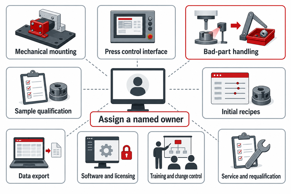
Common hardware must be separately identified from installation, qualification and ongoing support. Comparable quotations must cover the same application and assign the work needed to put monitoring into production. A monitor only price can’t disclose who will connect the press, isolate bad parts, create recipes or provide useful records to the customer.
For example, if one offer provides a monitor and sensor and the other provides installation and a sample study, include the agreed hardware once. Compare the rest of the work below. These columns are suggested responsibility allocations to negotiate, and not claims about any named vendor’s standard package.
| Work item | Monitor-only route: assign to | Integrated route: confirm | Limitations / Not suitable for |
|---|---|---|---|
| Mechanical mounting | Buyer or press integrator | Named installer and drawing | Unverified force path or applicator clearance |
| Press control interface | Controls engineer | Signal list and reaction sequence | Alarm without defined machine response |
| Bad-part handling | Line integrator | Included stop, cutter or isolation hardware | Displayed reject without physical containment |
| Sample qualification | Buyer quality team and supplier | Fault definitions and acceptance record | Unlabelled or unrepresentative samples |
| Initial recipes | Application engineer | Named product combinations | One generic recipe assumed valid for all parts |
| Data export | Buyer controls or information team | File fields, timestamps and sample IDs | Screen view without retrievable evidence |
| Software and licensing | Purchasing and system owner | PC needs, licences and version support | Unpriced mandatory software or access dependency |
| Training and change control | Production and engineering | User roles and recipe approval procedure | Uncontrolled edits after acceptance |
| Service and requalification | Maintenance and quality | Support scope and change triggers | Replaced equipment returned without review |
The distinction does have a basis in reality. In the case of Wiring Harness News’ interview with Schaefer’s Steffen Dosch, cutting the wire is conditional on the bad part cutter being installed. Don’t extrapolate that product’s features to a different supplier. Place the required action and the supplied hardware in your own contract.
A good report should describe the recipe and application, and not just say “quality passed.” Ask for an example export before committing the investment. If electrical testing or connector insertion is also required, define those processes in a separate interface. Automated connector testing equipment covers a different process boundary from crimp-force analysis.
Industry Outlook: acceptance evidence and integration boundaries
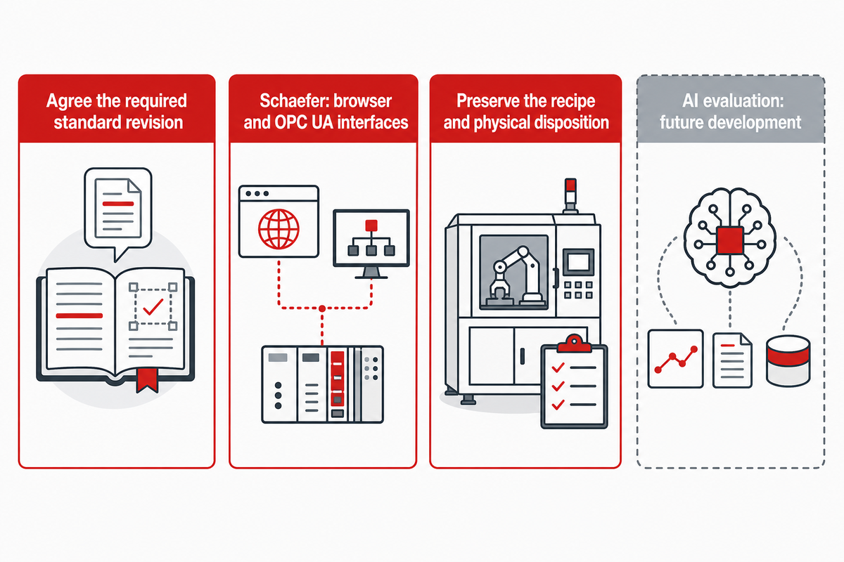
Define the required standard revision and portable application evidence for current purchasing decisions. New interfaces and classification research can improve how engineers inspect results, but they do not remove the need to qualify detection on the intended connection. Define the required records and release limits before choosing a monitor or assembly line supplier.
The official IPC/WHMA-A-620 Revision F listing shows an October 2025 publication date. An older shop landing page can still point a reader to an earlier revision. For a 2026 project, define the agreed revision and product requirements on the acceptance document. The latest catalog doesn’t automatically replace the revision in an existing customer agreement.
The types of evidence buyers can request are changing with the times as well. Schaefer describes how a browser-based interface and an OPC UA interface are available for its own product. AI-based defect evaluation is mentioned as a future development. Separately, the 2026 Hofmann research studies explain machine-learning classifications. None of these descriptions confirm that these features are part of every monitor or that ZEUEE has those algorithms.
Ask a supplier to show an exported record for one accepted part and one challenged defect, with the recipe versions and their physical dispositions. Evaluate what survives a restart, a software update, or a move to a different press. If those records cannot be linked, the buyer cannot readily repeat the original comparison after a change.
Choose the supplier route and integration boundary
For existing wire processing equipment, consider the actual application with the monitor supplier and press integrator. For feeding, crimping and downstream inspection in one project, consider a configured machine. ZEUEE’s connector crimping machines with configurable inspection are relevant to that integration route. The public offering isn’t an indication of a universal missing-strand threshold or of standalone monitor manufacture.
Send terminal and wire drawings, sample materials, target defects, planned production conditions and required test records. Ask ZEUEE what’s included in the proposed machine and what remains the buyer’s responsibility. Broader custom assembly-machine integration should be scoped around the actual sequence, with each inspection method justified by the defect it must address.
Key takeaway
Buy against an agreed application trial and installed responsibility record. Separate the observed detection result from the physical handling of the part, and retain the evidence needed to repeat both checks after a change.
Frequently asked questions
Does crimp force monitoring work on every terminal and wire combination?
Crimp force monitoring requires an application-specific feasibility check; universal coverage should not be assumed.
Terminal forming behaviour, conductor contribution, tooling and normal variation affect the available signal. Supply the actual materials and define the smallest relevant defect. The supplier should compare independently accepted samples with controlled faults and record the results separately. Where good and defective signatures overlap, add an appropriate inspection method or change the process before accepting a coverage claim.
Which crimp force monitoring system is best for a benchtop press?
A suitable benchtop system fits the press and proves the required detection and operator response on your application.
Compare sensor mounting, stroke triggering, applicator compatibility and the available stop interface before comparing display features. Request a sample trial using your wire and terminal, including accepted production variation. Then check how an operator locates a rejected part, acknowledges the alarm and restarts. A low hardware price is incomplete without the installation, recipe and training responsibilities needed to use it properly.
What is the IPC crimp pull test method?
The applicable pull-test procedure must come from the agreed standard revision, terminal requirements and customer control plan.
Do not derive a universal force limit from a monitor setting or a public standard summary. Confirm specimen preparation, test arrangement, loading procedure, acceptance value and failure reporting in the governing documents. Record the conductor and terminal identities with the result. The public IPC catalogue verifies the edition and general scope; it does not provide the complete paid test requirements used for your product.
Why is my crimp force monitor rejecting good parts?
Good-part alarms can result from process variation, an unsuitable reference or measurement setup changes.
Compare the current material, tooling and sensor installation with the qualified setup. Independently inspect the rejected samples before labelling the calls false. Adjust limits only through the agreed engineering review, then repeat the affected challenge tests.
Is crimping better than soldering for a monitored production process?
Crimping and soldering need different process controls; a force monitor alone does not decide which joining method suits the product.
Begin with the connection design, terminal requirements and service conditions. A crimped joint relies on the specified conductor, terminal and forming tool working together. Its force signature gives information about that mechanical operation. Soldering involves different materials and process variables, so the same force-based acceptance record cannot establish solder-joint quality. If the drawing already specifies a crimp, adding solder is a design or process change that needs the responsible engineering decision, not a shortcut for clearing monitor alarms. For a new product, compare the methods using the required electrical, mechanical and environmental qualification evidence. Once the joining method is selected, define its inspection plan and production controls. Buying a monitor is a later application decision; it should not be used to justify an otherwise unsuitable connection design.
Prepare an application review
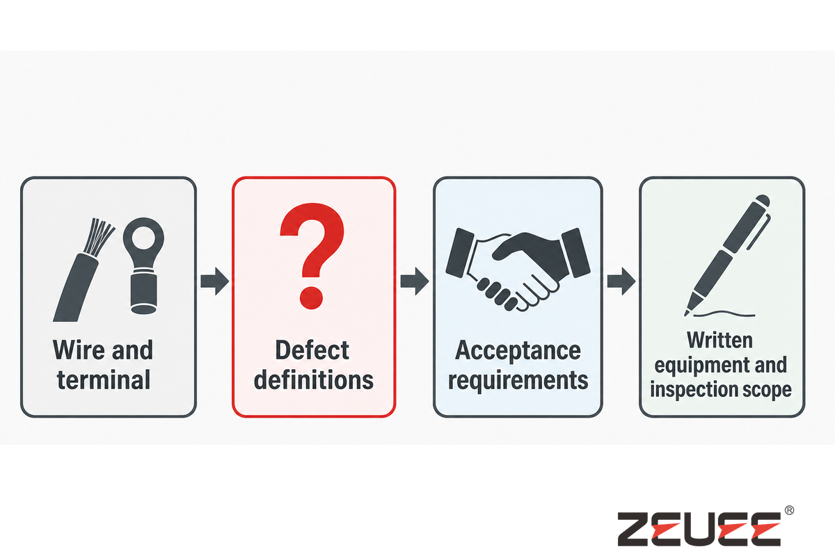
Bring the wire, terminal, defect definitions and acceptance requirements to the discussion. Contact ZEUEE about a connector-crimping application trial and request a written equipment and inspection scope.
Evidence note: this guide integrates public technical sources with an editorial framework for purchase. Hypothetical trial counts are examples, not test results or recommended sample sizes by ZEUEE. Research and third-party product capabilities remain owned by their respective entities. Final acceptance is governed by the documents agreed to for the application.
References & Sources
- Crimp Force Monitoring Rob Boyd, Assembly, 2009.
- Why Crimp Force Monitoring Is Important Gustavo Garcia-Cota, ConnectorSupplier, 2013.
- Transparent Machine Learning for Crimp Force Monitoring Using Phase-Based SHAP Explanations Hofmann et al., Industrial Artificial Intelligence, 2026.
- Quality Crimps in Three Steps Terry Curtis, Assembly, 2013.
- Measurement Uncertainty: Approach National Institute of Standards and Technology.
- Analysis of Pull Force Test Results for Crimped Connections National Aeronautics and Space Administration technical repository.
- IEC 60352-2:2024 Public Scope International Electrotechnical Commission.
- Confirming a Performance Threshold with a Binary Experimental Response Leber, Pibida and Enders, National Institute of Standards and Technology, 2019.
- Does the Proportion of Defectives Meet Requirements? National Institute of Standards and Technology.
- Monitoring Crimp Quality in Real Time Wiring Harness News, interview with Steffen Dosch.
- IPC/WHMA-A-620 Revision F Global Electronics Association official store.
WHY WE WRITE THIS
About ZEUEE Engineering Insights
ZEUEE shares technical guides based on real automation project experience. Since 2005, we have designed and manufactured non-standard automation equipment for connector assembly, wire harness production, robotic lines, vision inspection, and smart factory upgrades.
Founded in 2005
20,000 m² production base
120+ specialists
150+ R&D patents
ISO9001:2015 certified
![Automated Screwdriving: Torque & Cycle Time [Guide]](https://zeueeauto.com/wp-content/uploads/2026/10/automated-screwdriving-featured-768x512.png)




![Automated Screwdriving: Torque & Cycle Time [Guide]](https://zeueeauto.com/wp-content/uploads/2026/10/automated-screwdriving-featured-150x150.png)