Get in touch with Zeyu lntelligent Industrial Company

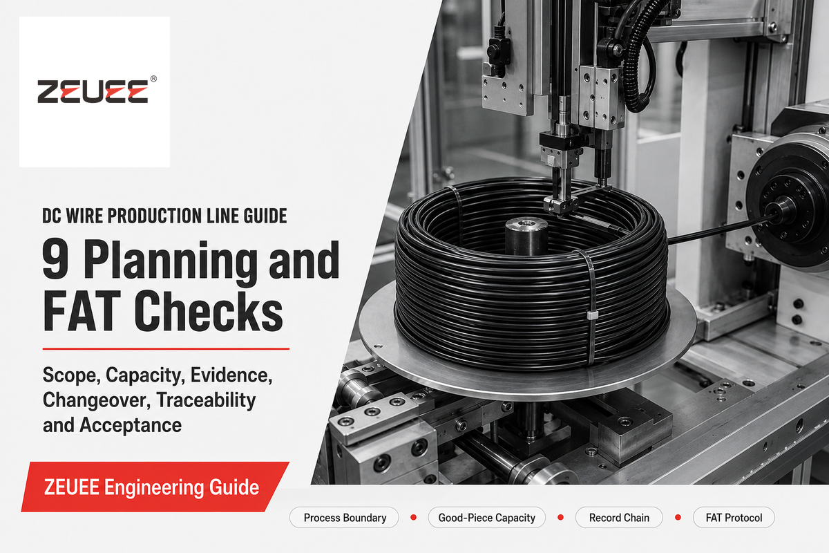
DC Wire Production Line Guide: 9 Planning and FAT Checks

Updated September 2026 · Written by Cherry
A DC Wire Production Line is a term that could mean two very different factories: upstream wire manufacture or downstream finished-cable assembly. This guide specifically focuses on equipment that transforms prepared wire, terminals, connectors, and molding material to a finished DC cable assembly. This guide won’t discuss copper drawing, conductor stranding, or primary-insulation extrusion.
This page stays with engineering decisions rather than rankings, price, or quotation. The planning sequence is simple to state but easy to break: freeze the finished cable, define each process handoff, reconcile good-piece capacity, control variant changeover, join records to the product, and witness those claims during acceptance. Readers searching for a supplier shortlist can begin with ZEUEE’s article on DC wire production line manufacturers. This document will stay with engineering decisions, rather than rankings, price, or quotes.
Quick answer
Plan a downstream DC cable assembly line from a controlled product definition, not a target rate alone. Specify incoming material, finished geometry, termination and overmold requirements, test ownership, measuring-system evidence, variant mix, traceability, safety interfaces, and project-specific FAT criteria before choosing a configuration.
Quick Planning Specs
| Process boundary | Prepared wire and components in; tested, labeled DC cable assemblies out |
|---|---|
| Capacity basis | Qualified good pieces per minute, tied to product mix and witnessed conditions |
| Quality basis | Named characteristic, method, limit, reaction, record, and release owner |
| Variant basis | Controlled material, tooling, recipe, test profile, label, and first-piece release |
| Acceptance basis | Agreed sample set, challenge plan, evidence format, open-issue owner, and signatures |
1. Which Process Boundary Does “DC Wire Production Line” Mean?
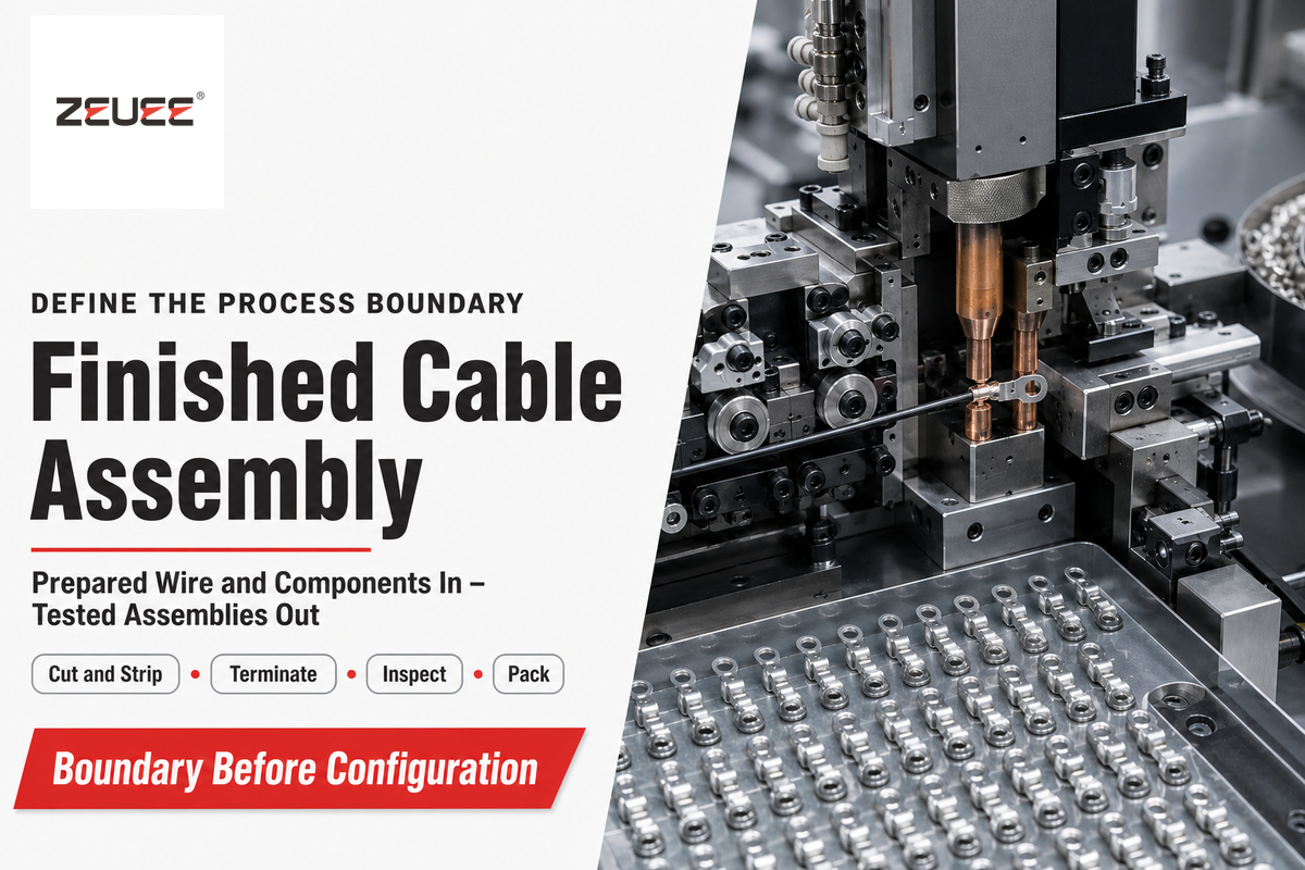
First, decide whether the project will make wire or assemble finished DC cables. Upstream cable manufacture is a separate process that starts with conductor and insulation production, while downstream assembly starts with prepared wire and components. Assembly begins with prepared wire and components, and then processes through cutting, stripping, terminating, inspecting, over molding, testing, labeling, and packing. The equipment, controls, evidence, and supplier set required aren’t interchangeable.
Upstream wire manufacture
- Begins with metal conductor and polymer systems
- Uses drawing, annealing, stranding, extrusion, cooling, and reel handling
- Produces insulated wire or cable by reel
- Needs conductor and insulation process evidence
Downstream cable assembly
- Begins with prepared wire, connectors, terminals, and molding material
- Uses cut, strip, terminate, inspect, overmold, test, label, and pack operations
- Produces a finished cable assembly
- Needs product, process, test, and genealogy evidence
This Boundary Fork helps to prevent a misquoting error. Search results for the focus term include drawing machines and extrusion lines, while the following ZEUEE example concerns finished-cable assembly. However, in the case of ZEUEE, the focus is on finished cable assembly. As such, a brief that simply states “make DC wire” can run the risk of being technically correct and still receive an offer for the incorrect factory.
The public scope of NASA-STD-8739.4A concerns interconnecting cable assemblies. That’s useful evidence for the downstream boundary, but it remains a NASA critical-work standard rather than a universal rule for every commercial cable. IPC/WHMA-A-620F also addresses cable and wire-assembly requirements and acceptance, not conductor drawing or primary extrusion.
Although a plant may need both domains, the contract must state their interface. State the incoming reel condition, cut-length responsibility, finished connector state, overmold boundary, test ownership, and packaging release. This downstream map doesn’t apply when the work begins with a copper rod.
2. What Must Be Frozen Before Line Design Starts?
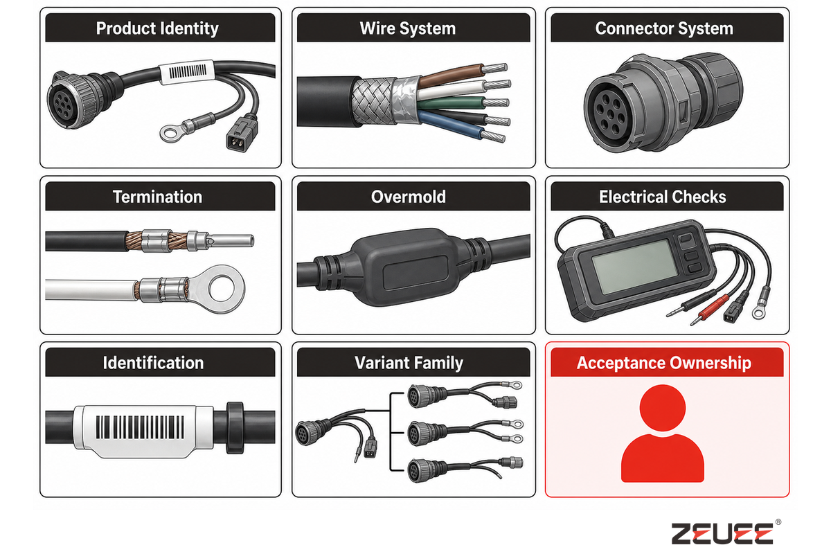
Freeze the finished cable and its controlled variation before freezing the machine design. One sample can show fit, routing, and construction, but can’t specify permissible variation, test method, revision status, or release authority. The Finished-Cable Input Dossier joins the physical sample to drawings, material records, acceptance methods, and ownership.
| Input category | Record to control | Decision it drives | Owner | Limitations / not suitable for |
|---|---|---|---|---|
| Product identity | Part number, drawing, revision, and approved sample status | Recipe and record key | Product engineering | A sample without a revision cannot govern release |
| Wire system | Conductor, insulation, cable diameter, reel state, and approved alternates | Feed, cut, strip, and handling | Material engineering | Nominal gauge alone does not define strip behavior |
| Connector system | Connector, terminal, plating, seal, polarity, and mating orientation | Tooling, insertion, and vision checks | Product engineering | A connector family name does not identify every cavity or terminal |
| Termination | Crimp, solder, weld, or other joined-state requirements | Process, tooling, and destructive checks | Process engineering | One termination method cannot be assumed across variants |
| Overmold | Material, geometry, adhesion, fill, flash, strain relief, and seal intent | Mold, recipe, cooling, and inspection | Product and process engineering | Appearance approval alone does not prove seal or strain relief |
| Electrical checks | Continuity, polarity, resistance, insulation, and any product-specific test | Tester, limits, routing, and reject logic | Electrical and quality engineering | Continuity alone cannot prove mechanical integrity |
| Identification | Marking, label content, barcode, and pack state | Printer, data source, and verification | Operations and quality | Readable print is not proof of correct source data |
| Variant family | Planned lengths, connectors, colors, molds, tests, labels, and mix | Change parts, recipes, buffers, and FAT samples | Program management | “Many SKUs” is not a controlled family definition |
| Acceptance ownership | Characteristic, method, limit, frequency, reaction, record, and signatory | FAT protocol and production release | Buyer and supplier jointly | A named document does not assign project responsibilities |
3. How Should the Process Hand Off Quality Evidence?
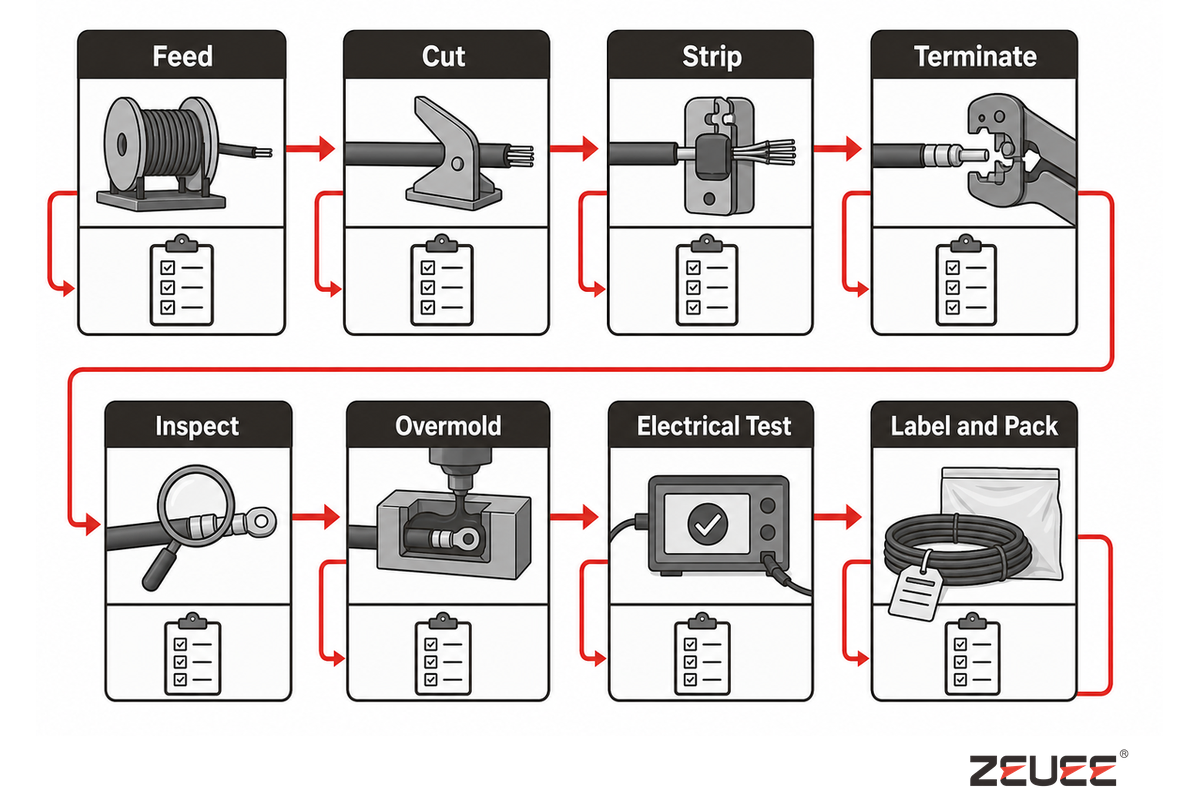
Each station handoff should answer the following: what entered, what changed, what was checked, what happens on failure, what record remains, and who releases the result. A PLC “complete” bit, if implemented without the work order, material, recipe, measurement, reject action, and next-operation permission, is insufficient.
| Operation | Controlled exit | Evidence | Failure reaction | Boundary |
|---|---|---|---|---|
| Feed | Correct wire and lot loaded | Material scan and work-order match | Hold start and remove mismatch | A scan cannot prove hidden material properties |
| Cut | Length and end condition meet the drawing | Method, result, tool state, and sample identity | Contain affected output and verify setup | Frequency is project-specific |
| Strip | Strip geometry and conductor condition are acceptable | Vision or measured result with limit set | Reject, inspect tool, and define suspect window | Visible checks can miss subsurface damage |
| Terminate | Joint geometry and process state meet the invoked specification | Tool, setting, process value, and planned test | Stop, contain, test, and disposition | Electrical pass does not replace mechanical evidence |
| Inspect | Named visible features are inside programmed limits | Image or feature result linked to product identity | Reject and retain reason | CCD cannot see every hidden defect |
| Overmold | Correct material, recipe, fill, flash, and position | Material lot, recipe version, cycle status, and inspection | Segregate, review process state, and disposition | Surface appearance does not prove a seal |
| Electrical test | Defined circuit characteristics pass their limits | Tester ID, program, limits, result, and product key | Auto-reject, contain, and diagnose | A passed characteristic is not whole-product proof |
| Label and pack | Correct identity, status, quantity, and pack state | Label verification and release record | Hold shipment and reconcile records | A correct label cannot cure an upstream defect |
Measurement validity belongs inside that contract. For this project, require instrument identity, calibration or verification state, resolution, repeatability, operating conditions, and applicable uncertainty in the FAT data package. When no external rule sets a fixed interval, NIST’s calibration guidance, updated in 2026, recommends an internal measurement-assurance program rather than treating a calendar interval as proof by itself. The stored number isn’t self-validating.
“The record of successful pull testing shall be traceable to the contact or ferrule, wire, crimp tool, crimp setting used.”
The quote doesn’t require NASA practice for a commercial line. It shows one evidence pattern: join product input, tool, setting, test, and production period in a retrievable record.
4. Where Does Real Line Capacity Come From?
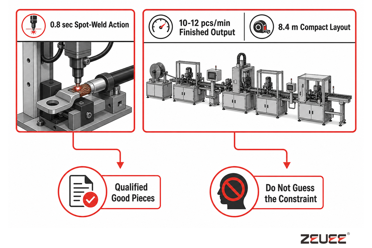
Finished output is the result of the constrained system, not the quickest motion. Reconcile operation time, load and unload, parallel nests, inspection, cooling, buffers, reject handling, maintenance, scrap, rework, changeover, blocking, starvation, and product sequence. Then count qualified good pieces during a stated window and mix instead of quoting one station time.
One useful public example from the Lean Enterprise Institute cycle-time reference gives a worked machine example. That machine has a 20 sec cycle, 30 sec of combined load and unload, and 30 sec of changeover allocated across a batch of 30. Its effective machine cycle becomes 51 sec, not 20 sec. The worked example illustrates the arithmetic scope before predicting output.
0.8 secpublished spot-weld action
10-12 pcs/minpublished finished output
8.4 mpublished compact layout length
ZEUEE’s first-party page publishes a 0.8 sec spot-weld action and 10-12 finished pieces in 60 sec. A standalone 0.8 sec action fits 75 operation cycles into 60 sec, while the finished rate corresponds to about 5 sec to 6 sec per piece. The constraint shouldn’t be guessed.
That same page lists a 28 kW system, 220/380 V supply options, and 0.4-0.7 MPa air pressure for the published configuration. Those figures belong to that commercial example, not to every DC cable line. They explain the need for a capacity review of the utility state and installed interfaces. Keep the commercial handoff on the solution page.
For NIST research into multi-job serial systems, throughput and bottlenecks are assessed based on the product mix. This plays a role when a short cable, a long overmolded cable, and a connector variation share a line. Factors such as sequence, buffer size, cooling, test time, and rework can influence the active constraint. Optimizing an operation that’s already fast can yield no finished capacity.
Cycle-Time Reconciliation Ledger
For each claimed rate, record product revision, mix and sequence, local operation times, parallel capacity, buffer conditions, planned and unplanned stops, maintenance state, inspection and cooling, reject and rework treatment, measurement window, good-piece definition, and witness.
5. What Quality Evidence Belongs at Each Stage?
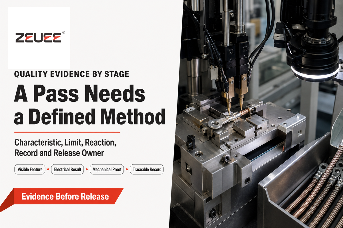
Stage quality must correlate product risk with prevention, detection, containment, and release. “100% inspected” has little meaning until it identifies the characteristic, method, limit, test coverage, failed-state response, retained record, and owner. Testing each unit for continuity does not guarantee achieving targeted stripping, termination strength, seal integrity, or material identification.
IPC’s public revision table records IPC/WHMA-A-620 as Revision F at 10/25. The public scope of the standard establishes requirements and acceptance of cable and wire assemblies. It doesn’t validate the entire process, determine the appropriate class for the customer, or establish a fixed in-process and final inspection for all instances. Ownership for sampling remains in the project quality plan.
| Wire-size cluster | NASA minimum tensile strength | Evidence use | Limitations / not suitable for |
|---|---|---|---|
| 28 AWG | 22 N (5 lbs) | Bounded contact-conductor pull example | Not a default limit outside the NASA scope |
| 26 AWG | 36 N (8 lbs) | Bounded contact-conductor pull example | Confirm conductor material and invoked requirement |
| 24 AWG | 36 N (8 lbs) | Bounded contact-conductor pull example | Does not define a sampling frequency |
| 22 AWG | 57 N (13 lbs) | Bounded contact-conductor pull example | Tool and terminal pairing still matter |
| 20 AWG | 92 N (21 lbs) | Bounded contact-conductor pull example | Not proof of connector retention |
| 18 AWG | 142 N (32 lbs) | Bounded contact-conductor pull example | Not proof of sealing or flex life |
| 16 AWG | 183 N (41 lbs) | Bounded contact-conductor pull example | Do not transfer to another conductor system |
| 14 AWG | 290 N (65 lbs) | Bounded contact-conductor pull example | Verify test speed and fixture under the invoked method |
| 12 AWG | 459 N (103 lbs) | Bounded contact-conductor pull example | Not a commercial-line universal acceptance table |
NASA’s method defines a travel speed for tensile testing of 25.4 ± 6.3 mm per minute and, for unspecified contact conductor combinations, a minimum of 60% of the wire tensile strength. Although these are traceable numbers, their importance is more about the method. An acceptance number needs a defined specimen, method, fixture, speed, scope, and record. This method shouldn’t be copied into a commercial specification without review for applicability.
Do
- Name the characteristic and method
- Bind the result to instrument and product identity
- Define containment and disposition
- Assign sampling and release ownership
Don’t
- Turn “100% tested” into a whole-product claim
- Assume CCD sees hidden damage
- Use continuity as a pull-strength proxy
- Treat auto-reject as process capability
When not to buy a fully integrated line
A fully integrated line is a poor first purchase when product revisions are still moving, variants aren’t grouped into a controlled family, joining processes remain unstable, test limits lack owners, or demand can’t be expressed as a mix and sequence, because automation freezes those uncertainties into tooling, recipes, interfaces, and software.
Consider staged cells or a pilot process when engineering changes are frequent, the available materials don’t have approved alternatives, and a destructive-test strategy is open, or if the fault-reaction logic hasn’t been agreed upon. This isn’t a criticism against automation. It’s a definition of the boundary beyond which automation introduces repeatability instead of hiding unresolved work on the product. The automated assembly line overview aids this decision in the context of a wider line architecture.
6. How Should Mixed-SKU Changeover Be Released?
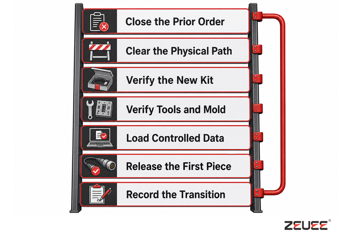
A recipe selection is part of one step of the changeover process, not a release. Variant Reset Ladder closes the prior order, clears material, verifies the new lots and tooling, loads approved data, confirms test and label limits, runs the first piece, reviews evidence, and records authorization. Safety controls remain a separate hold point.
- Close the prior order – reconcile accepted, rejected, reworked, and remaining pieces.
- Clear the physical path – remove prior wire, connectors, terminals, labels, and packaging.
- Verify the new kit – match material lots and approved alternates to the controlled work order.
- Verify tools and mold – confirm identity, revision, condition, and any required setup checks.
- Load controlled data – select the approved recipe, inspection program, electrical limits, and label source.
- Release the first piece – review the defined evidence before normal output.
- Record the transition – retain who changed, checked, challenged, and authorized the line.
At least one planned variant transition should be challenged during FAT. Even a clean nominal run can miss stale labels, previous-SKU material, the wrong electrical program, an unchecked mold, or a record key that doesn’t reset. Measure changeover time only after the start and stop states are defined, then state the product pair and conditions alongside the result.
Quality authorization can’t replace control of hazardous energy. As stated in 29 CFR 1910.147, servicing and maintenance involve setup, adjustment, clearing jams, and tool changes. If any unexpected energization, starting, or release of stored energy poses a hazard to workers, then it shouldn’t be considered minor servicing. The minor-servicing exception has conditions; it doesn’t create an automatic exemption for a recipe setting.
The line brief should show two releases. Safety release is based on the site’s risk assessment, energy-control procedures, guarding, and authorized-person rules. Quality release is based on materials, tooling, software, inspection, test, first-piece evidence, and product authorization. Both can happen during a single changeover, but neither asserts the other.
7. Can One Finished Cable Be Reconstructed From Its Records?

Traceability works when one finished cable or controlled lot can be reconstructed without searching disconnected screens. The One-Cable Record Drill starts from the released identity, retrieves materials, revision, recipe, tooling, inspections, electrical results, rejects, rework, label, pack, and sign-off, then reverses from a suspect input to affected output.
Start with a stable product key. Unit identity may suit one product while lot identity suits another. Granularity and retention follow product risk, customer rules, and containment needs.
One-Cable Record Drill
- Retrieve work order, product revision, and release state.
- Retrieve wire, connector, terminal, and overmold material lots.
- Retrieve recipe, software, tooling, mold, and approved settings.
- Retrieve visual, dimensional, mechanical, and electrical evidence.
- Retrieve reject, rework, retest, and final disposition.
- Retrieve label source, pack state, and shipment release.
- Reverse one suspect lot or recipe revision to the affected population.
A useful record also exposes failed joins. An image without a product key, a test result without program version, or a rework entry without a new release decision is data but not genealogy. Record retrieval should be witnessed during acceptance, not demonstrated later through a custom database query that production users can’t repeat.
8. How Should a DC Wire Production Line FAT Be Structured?
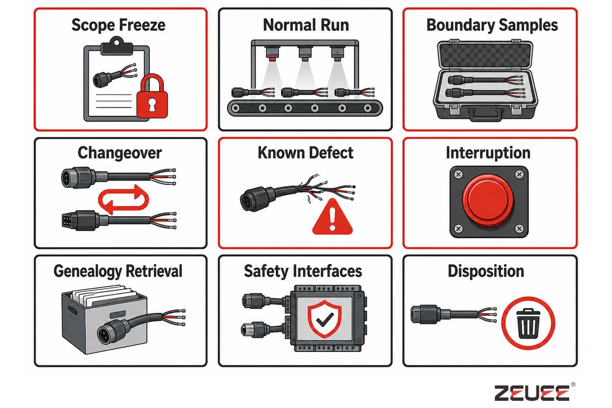
A useful FAT witnesses the agreed process boundary under controlled samples, not only an easy production run. Its protocol should identify revisions, methods, measuring-system state, sampling ownership, normal and boundary conditions, one planned changeover, selected fault reactions, containment, restart, data retrieval, open issues, and authorized signatories.
| Challenge | Evidence | Pass basis | Owner | Limitations / not suitable for |
|---|---|---|---|---|
| Scope freeze | Approved revisions, samples, and assumptions | Signed baseline | Buyer and supplier | Does not close undocumented product changes |
| Normal run | Good-piece count, time basis, stops, and rejects | Agreed witnessed condition | Operations | Does not prove sustained site output |
| Boundary samples | Named variants or controlled condition edges | Project limits and methods | Product and quality | More nominal pieces cannot replace this challenge |
| Changeover | Prior close, new setup, first-piece evidence, and release | Variant Reset Ladder complete | Operations and quality | One pair does not represent every variant pair |
| Known defect | Agreed safe challenge and programmed reaction | Detect, reject, identify, and contain | Controls and quality | Only proves the challenged fault |
| Interruption | Stop, recovery, restart, and in-process product handling | No uncontrolled release | Controls and operations | Factory utilities differ from the site |
| Genealogy retrieval | Forward and reverse One-Cable Record Drill | Required fields joined and repeatable | Quality and IT | Retention duration remains project-specific |
| Safety interfaces | Guarding, energy control, stops, and defined responsibilities | Applicable plan and site requirements | Safety owner | FAT cannot approve every installed-site condition |
| Disposition | Passed items, deviations, evidence, owner, due date, and signature | No ownerless open item | Program management | Shipment approval is not site acceptance |
The official IEC 62381:2024 page describes FAT, optional factory integration testing, SAT, and site integration testing for process-industry automation. Its lesson is bounded but useful: adapt tests to the applicable specification, agreed scope, responsibilities, and project procedures. Do not present it as a universal cable-line mandate.
FAT can support shipment, while FIT, SAT, SIT, and ramp evidence answer different integration or site questions where those layers apply. Assign an owner to each interface, so a factory pass doesn’t get confused with installed performance.
Sample quantity and frequency require explicit owners. Variants should be agreed to by the buyer and supplier, along with the measurement state, criteria for passing, failure, and the rules for retesting prior to the agreed witness date.
9. What Belongs in the Technical Requirement Brief?
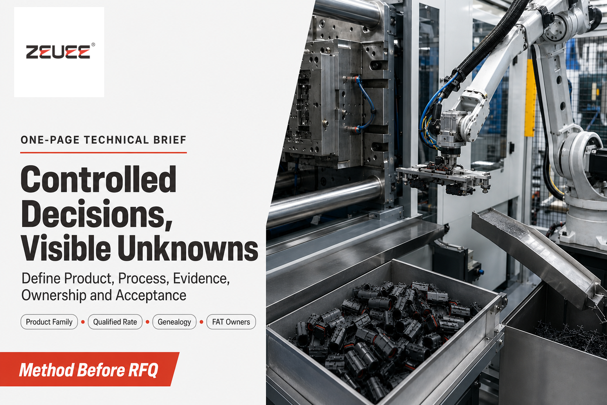
The technical brief should fit one page of controlled decisions plus a visible list of open assumptions. They include the production boundary, the product family, materials, process and test ownership, measurement validity, variant mix, qualified capacity basis, changeover, genealogy, safety interfaces, acceptance layers, sample sets, and responsible signatories.
Technical brief fields
- Process start, process end, and buyer-supplier responsibility boundary
- Product numbers, revisions, samples, drawings, and planned variant family
- Wire, connector, terminal, overmold, label, and packaging inputs
- Termination, inspection, electrical test, and release characteristics
- Measurement-system identities, states, methods, and evidence formats
- Product mix, sequence, qualified good-piece rate, and operating assumptions
- Changeover state, safety hold points, first-piece release, and authorization
- Unit or lot genealogy, retrieval, containment, retention, and data export
- FAT, optional FIT, SAT, SIT, ramp boundary, samples, owners, and open issues
Having clarified these, one can refer to the DC wire production line solution. That page owns line configurations, published specifications, supplier evidence, quotation, and RFQ. This guide will not duplicate those conversion sections in order to keep the two pages of utility for different search objectives.
To broaden the RFQ readiness review, ZEUEE also has publicly available a manufacturing RFQ readiness checklist and a production line automation guide. Use those resources for project framing, while the brief above remains specific to finished DC cable assembly.
The page About ZEUEE identifies the commercial party. Independent engineering claims remain tied to the public sources below.
Key takeaway
A defensible DC cable line request defines the finished product, qualified good-piece rate, evidence chain, safe changeover, genealogy, and acceptance ownership before it asks for a machine configuration.
Review a Defined Cable and FAT Scope →
FAQ: DC Wire Production Line Planning
These answers provide a delineation between production-line planning and wire sizing for end-use requirements. Gauge and ampacity concern DC circuit design; this guide concerns the equipment and evidence used to manufacture an already defined cable assembly. Ensure the product drawing and the associated electrical requirements are provided prior to the selection of the machine.
Is a DC wire production line the same as a wire extrusion line?
No. A wire extrusion line makes insulated wire, while a downstream assembly line turns prepared wire and components into finished cable assemblies; their drawings, equipment, process controls, and acceptance evidence therefore differ.
A wire extrusion line belongs to upstream cable manufacture and applies insulation or a jacket after conductor-forming steps. A downstream DC cable assembly line starts with prepared wire or cable and adds measured cutting, stripping, termination, inspection, overmolding, electrical checks, labeling, and bundling. A project can require either boundary or both, but drawings, equipment, controls, and acceptance evidence differ. The upstream line releases cable by reel; the downstream line releases a defined assembly with connectors, polarity, overmold, tests, identity, and pack state. State the incoming material and required finished output before comparing suppliers.
What information should be ready before planning the line?
Prepare controlled product data, material definitions, process choices, checks, variants, traceability, capacity conditions, and acceptance ownership before equipment layout, supplier comparison, and FAT protocol design begin.
Prepare product drawings and revisions, representative samples, conductor and insulation details, connector or terminal definitions, polarity, termination method, overmold and strain-relief requirements, inspection and electrical-test methods, labeling and pack state, expected product mix, and required traceability granularity. Identify which variants will be demonstrated at FAT, who owns each decision, and which assumptions remain open. One sample alone can’t define permissible variation, test method, revision control, or release authority.
Does 100% continuity and CCD inspection guarantee zero defects?
No. Full screening covers only the characteristics and limits that the installed tests are designed to measure; it doesn’t establish pull strength, sealing, hidden damage, material identity, or long-term performance.
Continuity can detect an open circuit, and vision can inspect defined visible features, but neither proves pull strength, hidden conductor damage, seal durability, material identity, or long-term performance. Name each risk, detection method, failed-state reaction, record, and release owner. “100% inspected” matters only when the characteristic and method remain visible.
How should line output be specified?
Specify qualified good pieces per minute with the product mix, quality state, stops, rejects, and measurement window attached, keeping the product sequence, witnessed conditions, measurement window, and quality rules beside the number.
Separate local operation time, effective cycle, witnessed output, qualified output after rejects, and sustained site production. Record sequence, buffers, changeover, maintenance, scrap, rework, and utilities beside the number. Different process boundaries can carry different valid rates.
What should a FAT test besides normal production?
FAT should test boundary samples, changeover, selected faults, containment, recovery, evidence retrieval, and signed issue disposition, including measurement state, retest rules, and named owners for every open issue.
Witness approved revisions, methods, measurement state, one planned transition, safe fault reactions, containment, restart, and genealogy retrieval. Assign remaining integration, site, and ramp checks. Quantities, limits, and frequency stay project-specific.
Can one line handle several DC cable variants?
Potentially, but variant capability must be defined by changed materials, tooling, programs, tests, labels, and release work, with a representative transition and retained first-piece authorization before production restarts.
Name each material, tooling, program, test, label, and pack change. Then define clearing, kit checks, safety controls, first-piece evidence, and authorization. Witness a representative transition instead of accepting “multiple SKUs” as proof.
The Final Planning Rule
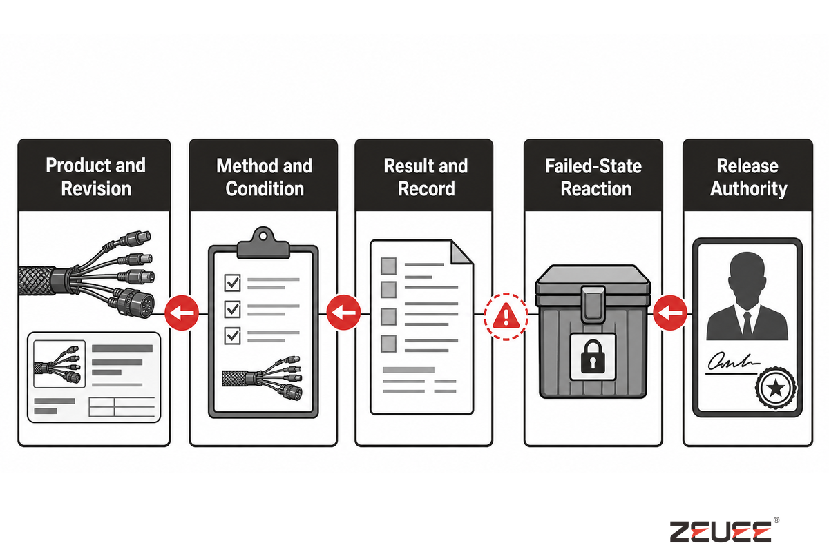
A production line should be considered as a controlled path from approved product data to released cable evidence. Each significant claim should answer a backward question: which product and revision, which method and condition, which result and record, which failed-state reaction, and which person or function had authority to release it?
This delineates a machine demonstration from a production system. These nine checks enable extensive reviews, maintain transparency for assumptions, and reserve the solution page for configuration and quotation.
Related Articles
- DC Wire Production Line Manufacturers – supplier discovery and screening
- Production Line Automation Guide – wider automation architecture
- Automated Assembly Machines Guide – assembly equipment categories
- Automated Assembly Line Manufacturers – broader supplier comparison
How This Guide Was Built
The guide methodology separates DC cable assembly planning from ZEUEE’s commercial configuration and quotation page. Its process-boundary, capacity, measurement, safety, workmanship, traceability, and acceptance claims were checked against current public government, standards, research, and university sources. First-party ZEUEE specifications appear only as an attributed worked example.
References & Sources
- IPC Standards Revision Table – IPC
- NASA-STD-8739.4A catalogue record – NASA
- Crimp, pull-test, and traceability requirements – NASA
- Cycle Time – Lean Enterprise Institute
- Multi-Job Production Systems – NIST
- Recommended Calibration Interval – NIST
- 29 CFR 1910.147, control of hazardous energy – eCFR
- 14 CFR 21.137, bounded quality-system example – eCFR
- IEC 62381:2024 public catalogue – IEC
WHY WE WRITE THIS
About ZEUEE Engineering Insights
ZEUEE shares technical guides based on real automation project experience. Since 2005, we have designed and manufactured non-standard automation equipment for connector assembly, wire harness production, robotic lines, vision inspection, and smart factory upgrades.
Founded in 2005
20,000 m² production base
120+ specialists
150+ R&D patents
ISO9001:2015 certified
![Automated Screwdriving: Torque & Cycle Time [Guide]](https://zeueeauto.com/wp-content/uploads/2026/10/automated-screwdriving-featured-768x512.png)
![Automated Screwdriving: Torque & Cycle Time [Guide]](https://zeueeauto.com/wp-content/uploads/2026/10/automated-screwdriving-featured-150x150.png)