Get in touch with Zeyu lntelligent Industrial Company

Twist Pin Machine: A Complete Manufacturing Guide (2026)

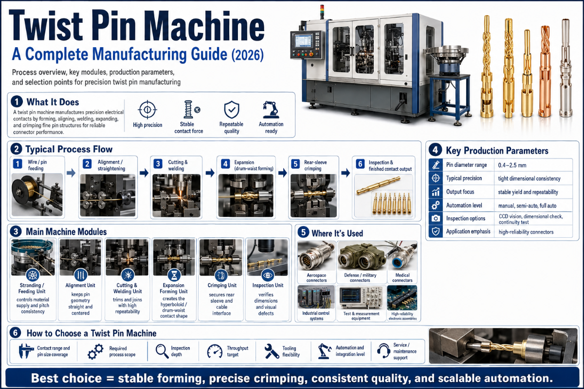
Complete Manufacturing and Sourcing Guide – for the Engineer, Buyer, and Planner of Hyperboloid Contact Assemblies.
Twist Pin Machine: How Hyperboloid Contacts Are Manufactured (Complete Guide)
A Twist Pin machine refers to a family of precision machinery designed to fabricate hyperboloid contacts – those small (0.2 to 0.8 mm in diameter, using 3 to 9 strands of beryllium copper wire), mission-critical building blocks for aerospace, defense, RF and test probe connectors. An industrial twist pin machine is very different from the sort of ubiquitous, screw-shaped fastener on Amazon used to anchor sofa covers. It is instead a six-stage automated line for stranding, cutting, welding, expanding, aligning, and 100% inspection of electrical contacts. This guide explains how this equipment works, the significance of hyperboloid geometry, machine configurations, relevant standards, and factors in automated versus manual assembly.
Quick Specs — Twist Pin Machine Parameter Reference
| Wire Diameter Range | 0.2 – 0.8 mm |
| Strand Count | 3 – 9 strands per twist pin |
| Stranding Throughput | 100 – 200 mm/min |
| Straightening Speed | up to 1,000 mm/min |
| Cutting + Welding Throughput | 12 – 15 pcs/min |
| Expansion (Bulging) Throughput | 10 – 15 pcs/min |
| Primary Material | Beryllium Copper C17200 (per ASTM B194) |
| Alternate Materials | Phosphor Bronze C5210, Beryllium Nickel C17510 |
| Standard Plating | Gold 0.5 – 2.5 µm over nickel underlay |
| Production Stages | 6-stage automated line (stranding → cutting → welding → expansion → alignment → inspection) |
What Is a Twist Pin Machine? Industrial Twist Pin vs. Upholstery Twist Pin
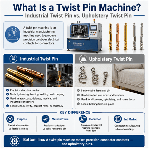
Perform a Google search for “twist pin” and the first thing you find is six-thousand-plus results pertaining to the do-it-yourself hardware category of upholstery twist pins, intended to secure fitted sheets, seat cushions, and slipcovers. That is not, however, the subject of this guide.
Industrial connector “twist pins” are electrically conductive contact elements commonly used in high-reliability connectors employed across aerospace, military, RF, and test-probe applications. Each is a complex structure built from multiple strands (3 to 9 typically) of beryllium copper wire woven together and then mechanically expanded midway along its length, producing a cage that forms the shape of a hyperboloid. When mating with a pin in a connector socket the structure flexes, hugging its mate across multiple contact lines and giving 7 to 10 redundant electrical contact points compared with the 2 to 3 single points on a formed or stamped contact. The result is a contact very resistant to shock and vibration, capable of many thousands of mating cycles without contact failure.
So then a “Twist Pin machine”is defined as an automated equipment line for the fabrication of “twist pins” – (or hyperboloid contacts as they are more professionally known) – from reels of bare wire through 6 different production stages into complete parts that can be assembled into connectors. Not a single machine, then, but six or seven different types of process machines combined in a line. Each stage is outlined below; followed by a look at industry standards and the considerations involved in deciding on automated vs. semi-automated vs. manual lines.
💡 Quick disambiguation
As this text will continue to “twist pin” when referring to the hyperboloid, wire-stranded, electrical contact connector part, not an upholstery tack, reader and machine designer alike: be advised. All further mentions of “twist pin” are to be interpreted as electrical “twist pin”.
Hyperboloid Contact Technology: The Engineering Behind Twist Pins
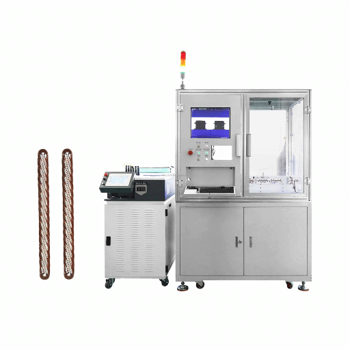
To understand why the existence of an automated twist pin machine is warranted it may prove insightful to contrast the mechanical and electrical behavior of a hyperboloid socket with that of its traditional, stamped-contact counterpart.
How Does a Hyperboloid Contact Work?
The geometry of a stamped contact involves pinching the male contact between a relatively few, thin-metal “blades” or” Fingers”. Each finger has a minimum surface contact area with the mating contact, supplying, perhaps, a total of three to five “real” contact points per socket in most designs. Since, each contact point may transmit perhaps only 3 milliohms or so of resistance at initial engagement with low levels of current – assuming good conditions – total socket resistance is perhaps 1 milliohm if there are no significant flaws, at best. However, if the assembly is subjected to vibration or extreme temperature cycling, it has been known for contact surfaces to slide even by micrometers against each other – called “fretting”. Even if no macro-movement is present, electrical conductivity may suffer as oxide films build upon the contacts. It is not uncommon for total contact resistances of stamped sockets to rise by an order of magnitude – from 3 milliohms up to over 25 milliohms — after only 500 or fewer cycles, often leading to contact failures from intermittent open circuits.
Hyperboloid sockets differ geometrically. Several thin wires – the individual strands of the twist pin – are anchored at both ends and drawn into a helical curve so that the midpoint of each wire bulges inwards. When the mating pin passes through each wire bends radially outwards and forces itself out radially independent of the others. 7-10 redundant contact lines are formed and a single failed strand wire does not make a failed contact. Instead vibration cleans the contacts rather than degrading the performance.
✔ Hyperboloid (Twist Pin) Advantages
- Shock tolerance up to 500 G — 10× a stamped contact
- Vibration 200 G continuous — 10× a stamped contact
- 7-10 contact lines that are redundant versus 2-3 points of single contact
- Stable ~3 mΩ contact resistance across mating life
- 10,000+ mating cycles with under 2% resistance rise
- Insertion force roughly half of an equivalent stamped contact
⚠ Limitations to Plan For
- Manufacturing cost is higher per pin than stamped contacts
- Must use age-hardened Beryllium Copper – supply of material may lag
- Contact lines need precise twist within 0.5 (tooling needs adjustment)
- Ideal contact operating temperature stays below 105 °C to preserve spring tension
- CMM or Optical Comparator are required for proper visual assessment
📐 Engineering Note
Running an actual twist pin through age-hardened C17200 Beryllium Copper achieves a contact force of 0.5 to 1.5 oz per contact, maintains contact force ±5 % through 10,000 mating cycles, and limits contact resistance <5 m total. Helix pitches must be held to approximately 0.0005 inch and strands to 0.001 inch – specifications that require the precision at each stage on ZE’s six-station production line.
“For stamped contacts with their few contact points, extended vibration will cause them to fail. mission-critical equipment can not risk their critical functions failing in a mission-critical environment and these designs have multiple points of electrical contact to insure against failures under vibration, which is why hyperboloid sockets have become standard for Micro D applications.”
— Aerospace connector engineering brief, paraphrased from a Cinch Connectivity technical document
The 6-Stage Twist Pin Manufacturing Process
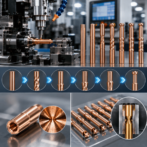
A complete ZEUEE twist pin machine assembly line has six purpose-built stations; each stage solves a specific aspect of the overall challenge, so that the lowest performing machine sets the line speed.
How Are Twist Pins Manufactured? The Six Stations Explained
From raw BeCu wire to finished product, the line’s process flow runs through these inspection steps:
| Stage | Machine | Throughput | Critical Parameter | QC Step |
|---|---|---|---|---|
| 1. Stranding | Twist Pin Stranding Machine | 100–200 mm/min | Helix pitch ±sub-degree, lay length 0.5–3 × OD | Inline tension monitoring |
| 2. Straightening + Cutting | Servo Cutting Machine | 1,000 mm/min straightening; 12–15 pcs/min cut | Cut length ±0.05 mm | Laser length gauge |
| 3. End Welding | Twist Pin End-Welding Machine | 12–15 pcs/min | Weld bead concentricity, no porosity | Optical bead inspection |
| 4. Expansion (Bulging) | Expansion / Bulging Machine | 10–15 pcs/min | Bulge diameter, hyperboloid waist profile | CMM dimensional check |
| 5. Alignment | Alignment / Straightening Machine | Matched to line | Pin straightness, end alignment | CCD straightness check |
| 6. Inspection | CCD + Laser Optical Inspector | 100% inline | Geometry, surface, plating coverage | Automatic reject + bin sort |
A total of three engineering-relevant points should be discussed when looking at these six stations. Stage 1: Stranding – this step is extremely precision sensitive, in that should the helix pitch deviate >0.5, subsequent stages can not possibly correct the contact profile. Stage 3: Welded-the weld is a critical element for guaranteeing the gas tight integrity of the crimp, without which oxygen is allowed to migrate into the strand, shifting contact resistance. Stage 4: Bulging-this process provides the unique shape and curvature that establishes contact pressure; without this step, the product looks and feels much the same as an ordinary, non-circular contact.
Throughput is currently limited by stages 4 and 6. For a mixed BeCu and Phosphor Bronze production setup on a six-stage automated twist pin assembly machine, 10-12 units per min would seem realistic on the sustained run of a 24/7 schedule would total about 4.3 M units/year before any time is subtracted for downtime for machine set up or routine maintenance.
💡 Pro Tip — Changeover Time
Industry publications reference changing the setting of one of 6 machines will result in 15 minutes of production time lost, over and above 2 hr per day loss on a whole line of machines for changeovers alone, and some will recommend implementing tooling to cut the set up time.
Material Selection: Why Beryllium Copper for Twist Pins
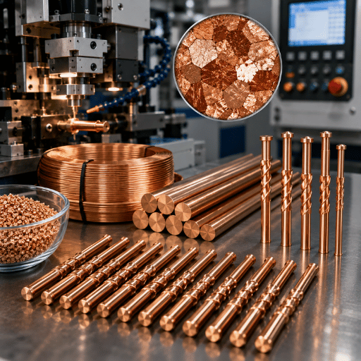
Material selection on a twist pin is no stylistic choice. It inextricably links to spring force retention, electrical conductivity and number of mating cycles survived. Three alloys encompass the roughly 95% of industrial twist pin production: beryllium copper C17200, phosphor bronze C5210, and beryllium nickel C17510. Each pair is associated with a unique application cluster.
| Property | BeCu C17200 | Phosphor Bronze C5210 | BeNi C17510 |
|---|---|---|---|
| Tensile Strength (heat-treated) | 1,100–1,380 MPa | 700–900 MPa | 760–965 MPa |
| Electrical Conductivity (% IACS) | 22–28% | 15–18% | 45–60% |
| Service Temperature | up to ~105 °C | up to ~100 °C | up to ~200 °C |
| Mating-Cycle Spring Retention | ±5% over 10K+ cycles | ±10% over 5K cycles | ±5% at elevated temperature |
| Relative Material Cost | High | Moderate | Very High |
| Reference Standard | ASTM B194 / B196 | ASTM B103 | ASTM B441 |
Standard aerospace, military, mission critical (MIL-DTL-83513 / 38999 / 55302) BeCu C17200, 50-100 in gold over nickel base
Material-Application Decision Framework
- Standard commercial RF, test-probe, telecom Class 2 (IPC/WHMA-A-620E Class 2) BeCu C17200 (standard cost alloy) or phosphor bronze C5210 (economy alloy)
- Continuous high-temperature instrumentation (>105 C) BeNi C17510 (titanium wheelhouse), naive alloys creep
- High current density, high temperature instrumentation (>150 C), BeCu C17200 essential; alloys creep
- Hybrid RF + power consolidation BeCu C17200 baseline alloy; consider silver underlay if current density exceeds 5 A per pin
A full alloy cross-reference appears in the ZEUEE connector assembly machines catalog across the six-station line.
Stranding Machine Types — Why Twist Pin Stranding ≠ Cable Stranding
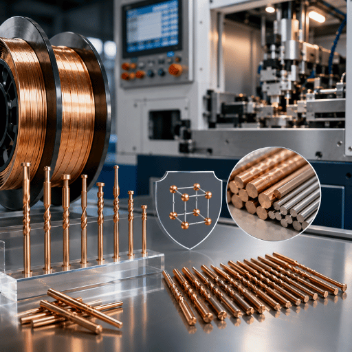
This is where most connector design engineers go wrong. The word “stranding” appears on both the data sheet of a 1,200 RPM LAN cable double-twist machine and on the data sheet of a twist pin stranding station. They employ a superficially similar mechanism–a take-up bobbin rotates about a payoff–but the engineering tolerance window between them is ten times. A cable stranding machine cannot make twist pins, even though both mechanically strand wire.
List of general stranding equipment clusters include tubular stranding machines, planetary stranding machines, rigid stranding machines, double-twist stranding machines, and cable bunching machines. Each one based on a different conductor geometry designed by all-purpose automated line builders. These all relate to cable-scale geometry: 0.5-5 mm multi-conductor clusters and higher, 8-25 D lay lengths, 50-200 m/min line speed. The critical metrics are cable conductor flexibility, DC resistance per kilometer, and the tensile reserve.
A twist pin stranding machine inverts all those parameters.
| Dimension | Cable Stranding Machine | Twist Pin Stranding Machine |
|---|---|---|
| Strand count per output | 7 / 19 / 37 / 61 (concentric standard) | 3 – 9 (single twist pin) |
| Wire diameter range | 0.5 – 5 mm (conductor scale) | 0.2 – 0.8 mm (micro scale) |
| Pitch tolerance | ±5 – 10% (functional) | ±sub-degree (contact geometry) |
| Lay length | 8 – 25 × OD | 0.5 – 3 × OD (helix angle critical) |
| Line speed | 50 – 200 m/min | 100 – 200 mm/min |
| Output form | Continuous reel (kilometers) | Discrete unit (mm + cutting) |
| Critical output parameter | Resistance, flexibility, tensile strength | Helix concentricity, spring force |
| Design intent | Power and signal conductor | Contact spring structure |
⚠️ The Honest Differentiator
Pitch accuracy in twist pin stranding is an order of magnitude closer than in cable stranding–sub-degree uniformity at 100-200 mm/min is the true competitive differentiator, not only the spindle speed. A cable strander which turns its spindle at 1,200 RPM cannot maintain sub-degree helix pitch accuracy on a 0.3 mm strand, the dynamics are incompatible, and the take-up is designed for kilogram-length output, not millimeter-length discretes.
That is exactly why engineering teams who retrofit a LAN cable stranding machine to produce connector pin material only make two compromises: contact geometry which cannot CMM it, and a line that cannot 100% inline optically inspect ever close out because the product is constant, not discrete. ZEUEE’s stranding-cutting-welding-expansion stack exists precisely because cable stranding cannot produce the discrete micron-pitch precision twist pins require.
MIL-Spec & Industry Standards — When Twist Pins Need Compliance
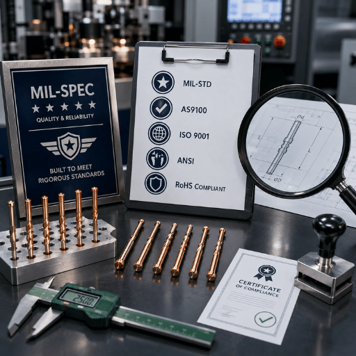
Whether or not a twist pin need conform to Military or Aerospace standard hinges on where the final connector assembly ultimately rests. Standards that come up in discussion have their layers of qualification: connector specification, material specification and workmanship specification; finally, an addendum applies to military/aerospace. Together, these standards come up most often in procurement discussions:
Standards Relevant to Twist Pin Production
- MIL-DTL-83513 (micro-D subminiature connector is a classic twist pin application).
- MIL-DTL-38999 (circular connector, temperature range).
- MIL-DTL-55302 (printed wiring connector).
- ASTM B194 (beryllium copper plate, sheet, strip and rolled bar).
- ASTM B196 (beryllium copper bar and rod – provides the feedstock for the twist pin wire).
- IPC/WHMA-A-620E, October 2022 (“Requirement for Wire Harness and Cable Assemblies” defines levels of quality control for electronic products, Class 1, 2 or 3; see below).
- NASA INST-EEE-002 (mandates twist pin style contacts for use in critical micro-d applications.
Choice among three IPC/WHMA-A-620E classes drives most procurement outcomes: Class 1 defines general electronic product standards, Class 2 covers products serving communication, data, and telephone equipment industries, and Class 3 sets high-reliability requirements for aerospace, medical, and military environments. Class 3 requires SPC records, an inspection environment at minimum 1,000 lux with 3,000–5,000 K color temperature, and adherence to the “Military & Space Addendum” for hardware exposed to thermal cycling, shock, and vibration that stress space-environment components and assemblies.
📐 Mill Test Certificate — Critical Fields
Aerospace and Military requirements include an attested Mill Test Report (MTR) for each lot of material specifying Alloy designation per ASTM standards, heat treat designation, Tensile Strength (min, max), Elongation (%), Electrical Conductivity (% IACS) and lot traceability (supplier). Without this, Class 3 lot rejection is the order of business.
Manual vs Automated Twist Pin Production — A Decision Framework
When a connector manufacturer evaluates building twist pin capabilities, the fundamental capital expense calculation is based on the capacity of a six-stage, fully-integrated, multi-step production machine versus that of other less-efficient solutions and methods for meeting their customers requirements. Here are the four variables used in that equation: • monthly volume • the specificity of Geometric tolerances • Fully Burdened labor cost • cost associated with Quality Rejection (lost production, rework, customer returns and warranty claims).
| Parameter | Manual | Semi-Automated | Fully Automated (6-Stage) |
|---|---|---|---|
| Sustained Throughput | 200 – 600 pcs/day per operator | 2,000 – 5,000 pcs/day | 10–12 pcs/min sustained ≈ 14K/day |
| Helix Pitch Precision | ±1 – 2° (operator-dependent) | ±0.5° | ±sub-degree (servo + CCD) |
| Scrap Rate | 2 – 4% | 0.5 – 1.5% | ~0.15% (100% inline CCD) |
| Operator Headcount | 25 – 35 | 8 – 12 | 2 – 4 |
| Initial Capital | Low (≈ $50K tooling) | Moderate ($120K – $250K) | $350K – $525K (incl. integration) |
| Typical Payback | n/a | 24 – 36 months | 12 – 24 months (labour + capacity) |
| Class 3 Compliance | Difficult (lot variability) | Feasible with audit overhead | Native (SPC + documentation) |
| Best Fit | <10,000 pcs/month, low spec | 10K – 50K pcs/month, Class 2 | >50K pcs/month, Class 3, mil/aero |
Quick Decision Rule
Should your needs be for >50,000 units/month, with geometric tolerances down to <0.5 degrees helix angle, and the contract demand IPC/WHMA-A-620E Class 3 quality standards, then the multi-stage, automated assembly solution may prove to be the most economical choice. For ~10,000-50,000 units per month, and perhaps Class 2 requirements, a hybrid/semi-automated process may be appropriate. At <10,000 pieces/month without a high-reliability requirement, manual processes under stringent operator certification will likely remain economically viable.
Two field-data points are worth knowing before you accept a quote. First, integration costs are consistently understated — industry trade publications report them running 40% above equipment quotes for first-time twist pin automation projects, with tooling and engineering accounting for most of that gap. Second, true per-operator cost runs roughly 1.5× the base labor rate once benefits, training, and turnover are factored in — the fully burdened overhead has averaged around $30K per year per operator in industrialized markets, a figure that flips the manual-vs-automated efficiency calculation faster than equipment ROI alone.
For procurement teams ready to scope a custom line, download the full twist pin spec sheet for line-level throughput, footprint, and integration data, or request a custom quote for your twist pin production line.
Common Pitfalls in Twist Pin Manufacturing — Field Lessons
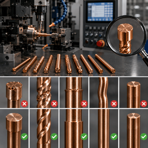
These five are the top causes of twist pin production failures-none of which can be inferred from your data sheet, all of which appear after your first lot ships and the qualification engineer on the other side of the fence pulls 30 pins for cross-sectioning.
⚠️ Pitfall 1: Helix Pitch Drift from Worn Spindle Bearings
Spindle bearings may take 18 to 24 months of steady production before they get worn to the point where they start knocking the helix pitch outside that less-than-one-degree range. At that point, the contact geometry doesn’t pass CMM measurement, even if the welding and wire stations are performing flawlessly. The Solution: Implement daily, each-shift, random CMM inspections on the stranding result-not just on the completed pin. (An article in an industry trade paper indicated that scrap can climb to a shocking 4% in this area before automation.)
⚠️ Pitfall 2: Incomplete BeCu Heat Treatment
BeCu C17200 must be age-hardened in a controlled atmosphere. Under-aging drops tensile yield by 15% and accelerates spring-force decay, which means contact-force retention falls outside the ±5% over 10,000 mating cycles envelope and pins that initially pass inspection later fail endurance testing. Mitigation: require the Mill Test Certificate to list heat-treatment state explicitly (TF00, TH04, etc.) and audit a sample lot using HRB or HV hardness measurement.
⚠️ Pitfall 3: Plating Thickness Inconsistency
Gold plating thinner than 50 in lets the nickel underlay corrode through; thicker than 100 in is wasteful and prone to cracks with repeated flex. Fortunately most connector engineers already know that resistance will creep up from a clean 3 m to more than 25 m after about 500 cycles if the plating is anything less than completely uniform – this shows as unreliable test socket connection.Solution: XRF plating-thickness measurements on every lot, not every sample.
⚠️ Pitfall 4: Non-Hermetic End Weld
Failure The stage 3 end weld not being gas tight allows atmospheric oxygen to enter the bundle of strands over a period of time. This results in an ever-increasing contact resistance, despite the lack of any visible flaw. Solutions include, helium leak testing on a random sample of welded pins, as a complement, not as a substitute for visual or X-ray testing.
⚠️ Pitfall 5: AQL Sampling Replacing 100% Inline Inspection
AQL is insufficient for class 3 work. Failures at bottom 0.1% of lot are still mission critical. The solution is easy and expensive: 100% inline CCD/laser dimensional inspection on stage 6, with automatic sort rejects.
Alternative: supplier’s “100% inspection” statements are not useful unless accompanied by per pin, verifiable, inspection results.
Industry Outlook — Twist Pin Demand Drivers Through 2026–2028
Three concurrent forces are driving twist pin demand across aerospace, defense, and high-density electronics — and none are speculative. Each is already visible in public market sizes and in the technical choices aerospace OEMs are making for next-generation component efficiency and intelligent inspection workflows.
SWaP reduction in Aerospace. Aerospace connectors market grew to about US $3.26 billion in 2025 from US $3.51 billion projected for 2026 per Intel Market Research. That is ~7.6% year on year growth and within that the trend is for fewer MIL-C-39029 stamped contacts and more size and weight and power optimization driven hyperboloid sockets to facilitate new mission requirements in CubeSats, SmallSats, tactical UAV’s, even manned space. Aerospace technical discussions focus on the hyperboloid design, whose self-cleaning geometry withstands vibration and prevents the most common failure modes, which is fretting corrosion of traditional stamped and crimped aerospace contacts.
High Growth in Space and Defense. By themselves,ospace connectors will reach US $1.41 billion from US $1.07 billion in 2026 according to Research and Markets (7.1% CAGR through 2030). In broader scope, the overall Space & Aerospace connector market is forecast to rise from US $8.05 billion in 2025 to US $15.02 billion in 2035 (SNS Insider). These upward market trends strongly favor high reliability twist pin and hyperboloid style technologies over older stamped and crimped designs.
Tightening Processes through IPC/WHMA-A-620E. The October 2022 release enhanced controls to IPC/WHMA-A-620 Class 3 processes, in particular document-controlled process (SPC), inspection lighting, and full traceability across every element in the assembly. This directly has Tier-1 customers mandating those process and documentation controls through purchase orders that translate to the twist pin supply base pushing towards automated lines and full SPC, not semi-automated processes.
If You Are Planning 2026 – 2028 Twist Pin Capacity
- Build for IPC/WHMA-A-620E Class 3 compliance from day one. Retrofitting SPC capability onto a Class 2 line costs roughly 2-3× the price of specifying Class 3 in the initial line configuration.
- Verify sub-degree pitch precision holds across mixed BeCu / phosphor bronze production. Aerospace tolerance windows narrow every year under SWaP-driven miniaturization, and machine manufacturers who customize stranding spindles for specific alloy mixes are pulling ahead of generic-line competitors.
- Reserve capacity for 5G mmWave and EV 800 V applications. Hyperboloid contacts are now entering both spaces, and the lead time for a new six-station production line typically runs 60 to 180 days.
Frequently Asked Questions
Q: What is the difference between a twist pin and a regular crimp contact?
View Answer
Twist pin are hyperbola socket contacts constructed of helically wound individual strands to provide contact redundancy through a multi-line engagement with the mating male pin. Stamped socket designs simply squeeze the mating pin between 2 or 3 simple tangs to provide only a few, often single point or parallel contacts. twist pin multi-contact geometry provides 10x the vibration and shock survivability of simple designs, with mating cycle lifetime up to 5-20x greater.
Q: Why is beryllium copper preferred for twist pin manufacturing?
View Answer
BerylliumCopper (BeCu C17200) after heat treatment offers up to 1,100-1,380MPatensilestrength at 22-28% IACSconductivity.This combination offers a high yield strength, adequate conductivity material, enabling long service life across up to 10,000 mating cycles or greater.
Q: How many stages are in a complete twist pin production line?
View Answer
6. Stranding/Straightening/cutting/End welding/Expansion/Bulging/Straightening and 100% optical inspection, and so on, with 6 machines and a twist pin factory line in total, where line throughput is dictated by the bottleneck stage (likely Expansion) of 10 – 15 pieces/min, with reference to the 6-stage twist pin production line review above for stage-level particulars.
Q: Can a stranding machine for LAN cable also make twist pins?
View Answer
No. A LAN cable stranding machine is made for multi-conductor cable geometry – 0.5 – 5mm wires, lay length 8-25 OD, line speed 50-200m/min, and continuous reel output. A twist pin requires 0.2 – 0.8mm wires, lay length 0.5 -3OD, sub-degree precision in helix pitch, and millimeter-order discrete output.
Neither dynamics or the take up configuration are appropriate for a twist pin application. Compare in the chart at stranding machines above for the complete list of differences.
Q: What standards apply to military and aerospace twist pins?
View Answer
MIL-DTL-83513 (Micro-D), MIL-DTL-38999 (Series III round, -65 to +200 C), MIL-DTL-55302 (PCB mounted connectors); For the BeCu feedstock per: ASTM B194 / B196 For Production Workmanship: IPC/WHMA-A-620E Class 3 Workmanship The Mill Test Certificate requires: alloy designator, heat condition, tensile, elongation, conductivity, identification for lot trace – Any of the above is failure for Class 3 production work.
Q: What is the typical production rate of a fully automated twist pin line?
View Answer
We get approx 10 – 12 pieces per minute, maintained continuously throughout the 6 station line, although the cutting + welding station runs at 12-15 pcs/min, and the expansion station is rated between 10-15 pcs/min. Running continuously 24/7 gives approx 4.3 million pins annually, not factoring in any planned maintenance or changeovers. Actual bottleneck depends on what alloy is being processed and how often the line has to be changed over from phosphor bronze to BeCu.
About This Analysis
Drawing on over twenty years experience of the ZEUEE engineering team in producing hyperboloid contact twist pin production lines for the aerospace, defense, and RF connector OEMs, typical parameters are based on equipment we have successfully placed in service, while comparative performance and product comparisons draw from Cinch Connectivity, IEH Corp, and Connector Supplier technical briefs and documented research verified with our engineers (May, 2026).
References & Sources
- ASTM B194 — Standard Specification for Copper-Beryllium Alloy Plate, Sheet, Strip, and Rolled Bar — ASTM International
- ASTM B196 — Standard Specification for Copper-Beryllium Alloy Bar and Rod — ASTM International
- IPC/WHMA-A-620E — Requirements and Acceptance for Cable and Wire Harness Assemblies (October 2022) — IPC International & Wire Harness Manufacturers Association
- MIL-DTL-83513 — Connectors, Electrical, Rectangular, Microminiature — U.S. Defense Logistics Agency
- MIL-DTL-38999 — Connectors, Electrical, Circular, Miniature, High Density — U.S. Defense Logistics Agency
- MIL-DTL-55302 — Connectors, Printed Wiring — U.S. Defense Logistics Agency
- NASA INST-EEE-002 — Instructions for EEE Parts Selection — NASA Goddard Space Flight Center
Related Articles
- ZEUEE Twist Pin Machine — Full Production Line Specifications — six-station throughput, footprint, and integration data
- ZEUEE Connector Assembly Machines Catalog — hyperboloid, stamped, and crimp assembly equipment families
- About ZEUEE — 20 Years in Hyperboloid Contact Manufacturing — engineering heritage, patents, and named OEM customer base
WHY WE WRITE THIS
About ZEUEE Engineering Insights
ZEUEE shares technical guides based on real automation project experience. Since 2005, we have designed and manufactured non-standard automation equipment for connector assembly, wire harness production, robotic lines, vision inspection, and smart factory upgrades.
Founded in 2005
20,000 m² production base
120+ specialists
150+ R&D patents
ISO9001:2015 certified