Get in touch with Zeyu lntelligent Industrial Company
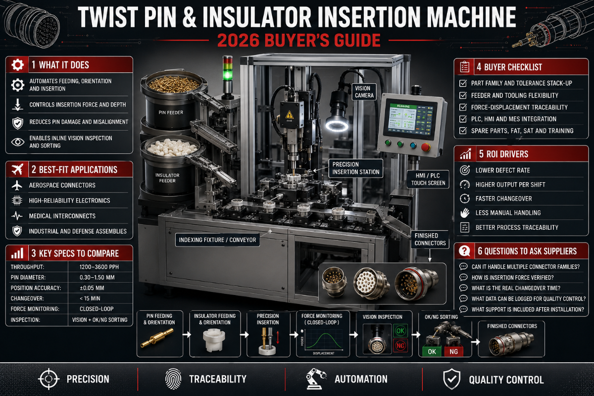
A twist pin & insulator insertion machine automates two of the most error-prone steps in connector assembly: pressing the metal contact (the twist pin) into its cavity, and seating the plastic insulator or housing that locks and isolates it. This guide explains how these machines work, how to choose one, how to keep insertion force in spec, and what to inspect — written for engineers and buyers who already know what the part is and now need to make a decision.
Quick Specs: Pin & Insulator Insertion at a Glance
| Insertion rate (fully automatic) | 10,000–18,000 insertions/hour (≈ up to 60 pcs/min, 20 pins/cycle on multi-pin heads) |
| Insertion rate (semi-automatic) | 1,500–5,000 insertions/hour |
| Pin diameter range | ≈ 0.30–2.0 mm contacts (machine-dependent) |
| Force monitoring | Force-vs-displacement signature per insertion (pass/fail window) |
| Drive | Servo or pneumatic actuation; PLC control |
| Acceptance standard | IPC/WHMA-A-620 (cable assemblies); NASA-STD-8739.4 for high-reliability |
Figures are typical industry ranges; confirm against your connector datasheet and a sample run. For high-reliability work, map them to NASA-STD-8739.4 acceptance criteria.
What this guide covers
- What the machine does (and what a “twist pin” really is)
- Core subsystems and the insertion cycle
- Twist pin vs press-fit vs crimp retention
- The 4-Lever Insertion-Force Playbook
- The Insulator-Insertion Defect Dictionary
- How to choose, cost, applications, and what’s changing
What a Twist Pin & Insulator Insertion Machine Actually Does
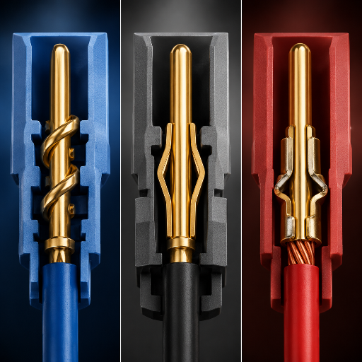
In connector manufacturing, a twist pin & insulator insertion machine performs two sequenced jobs on one station. First it inserts the contact — frequently a twist pin or the closely related hyperboloid contact, whose “basket” of fine, helically wound wires grips the mating pin at many points rather than two. Then it seats the insulator: the molded body, seal, or housing that holds the contact, sets pin pitch, and isolates each circuit. Getting both right, at rate, is what separates a production line from a bench operation.
First, a disambiguation that trips up search results. The “twist pin” here is an electrical contact, not the upholstery twist pins sold for slip covers. In connectors, that part is a precision component. Twist-pin and hyperboloid contacts are related but not identical — both use a wound-wire basket, and the exact term varies by maker — yet they share the same advantage: a hyperboloid contact is commonly rated on the order of 100,000 mating cycles, far beyond the few-thousand-cycle rating typical of many stamped contacts, because the wire basket distributes wear over many contact lines rather than two, as connector industry coverage of hyperboloid technology documents.
So why automate? Because both steps are unforgiving. Seat a contact 0.2 mm shallow and it can pass a visual check yet still fail in the field; an insulator pressed off-axis cracks or traps a bent pin. By contrast, a machine repeats the same force and depth thousands of times per hour, logs each one, and rejects the outliers — which is exactly what manual insertion can’t promise. For the buy-side view of a specific build, ZEUEE’s twist pin & insulator insertion machine solution page lists the configured options; this guide stays on the engineering and selection side.
💡 Key takeaway
Two jobs, one station: insert the contact, then seat the insulator. Real value here is repeatability and a logged pass/fail on each — not raw speed alone.
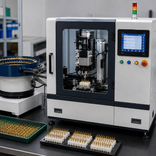
Inside the Machine: Core Subsystems and How Insertion Works
Strip away the branding and almost every connector assembly machine in this class shares four subsystems. Understanding them tells you where quality is won or lost.
- ✔Feeder. A vibratory bowl or a reel presents pins in a known orientation. Most jams trace back here — uneven reel winding, tangled pins, or burred tips disrupt feeding before the head ever moves.
- ✔Insertion head. A servo or pneumatic actuator drives the pin to depth. Servo heads let you program a velocity and depth profile; pneumatic heads are simpler and cheaper but blunter.
- ✔Force-monitoring. Inside it, a load cell records force against displacement for every stroke. That curve’s shape — not just the peak — is the quality signal.
- ✔Fixturing / nest. A tooled nest holds the housing square to the head. Poor fixturing is the hidden cause of off-axis insulator damage.
Each cycle itself is short: the feeder presents a pin, the head picks and aligns it, the actuator drives it through the insulator into its cavity while the load cell watches force build, and a verification step confirms seat depth before the nest indexes to the next position. Patented insertion methods such as US Patent 11,424,562 (press-fit insertion method) formalize how the drive stroke and verification are sequenced for repeatable results.
What are the biggest challenges with automated and semi-automated pin insertion machines?
In practice, the recurring problems are upstream of the press. Variation in pin length or pitch, abrupt tip transitions and burrs, uneven reel winding, and sharp cut-offs all cause feed faults and can scrape plating off the mating contact during insertion. None of these are “machine” faults exactly — they are pin-quality and tooling faults that the machine exposes. The practical fix is to qualify your pin supplier and tooling to the same standard you hold the machine to, because a high-speed head simply inserts a bad pin faster.
Twist Pin vs Press-Fit vs Crimp: A Contact-Retention Showdown
“Insertion machine” covers several retention methods that behave very differently. Choosing the wrong one is a design-level mistake no amount of machine precision fixes. The table below compares the methods you will actually weigh.
| Retention type | How it holds | Relative insertion force | Reworkable? | Mating cycles | Best fit |
|---|---|---|---|---|---|
| Twist-pin / hyperboloid | Wound-wire basket grips pin 360° | Low (manufacturer-reported ~40% lower) | Yes | ≈100,000 | High-vibration, high-cycle, aerospace/medical |
| Stamped spring contact | Cantilever beam preload | Medium | Limited | ≈5,000–50,000 | General signal & power |
| Press-fit (eye-of-needle) | Compliant section deforms in PTH | Medium–high | Yes (rework method exists) | Solderless, gas-tight | PCB backplanes, automotive ECUs |
| Solid press-fit pin | Interference fit, no compliance | High | No | Fixed | Rugged, thick boards |
| Crimp-then-insert | Wire crimped, then contact seated | Low at insertion | Yes (extract tool) | Connector-rated | Wire-to-board assemblies |
| Solder pin (thru-hole) | Solder joint after insert | Low at insertion | Reflow/rework | Joint-limited | Low-cost, low-vibration |
Those press-fit rows matter for one reason: a compliant press-fit pin makes a gas-tight, solderless connection when the pin’s press-fit zone is sized larger than the plated through-hole (commonly around a 0.60 ± 0.05 mm finished hole). That is why automotive and backplane builders favor it — compliant press-fit pins from established manufacturers such as TE Connectivity are engineered around exactly this fit — and why the insertion machine has to control force precisely, since the pin is deliberately deforming on the way in. Connector geometries built for this — such as the penetration-aperture design in US Patent 8,628,361 — exist specifically to make that controlled deformation repeatable.
The 4-Lever Insertion-Force Playbook
Insertion force is the number that decides whether a connection is sound. Too little and the contact sits shallow; too much and you buckle the pin or crack the insulator. Four levers control it, and an experienced line tunes all four rather than chasing one.
The 4 levers, in the order most teams should touch them
- Pin geometry & lead-in. A proper chamfer self-aligns the pin and lowers peak force; it’s the cheapest lever you have. Burred or square-cut tips raise force and scrape plating.
- Insulator material & hole prep. Hole diameter, draft, and resin (glass-filled vs unfilled) change the interference. Mismatched hole prep is the most common root cause of cracked insulators.
- Press profile & velocity. Slowing the final approach or using a multi-step “stutter” stroke reduces buckling — the approach formalized in US Patent 11,211,760 (stutter-step press-fit insertion process).
- Fixturing & alignment. A square, well-located nest keeps the load axial. Off-axis load shows up as an asymmetric force curve before it shows up as a reject.
📐 Engineering Note
Set the accept window on the force-vs-displacement signature, not a single peak value. Correct insertions show a recognizable curve: lead-in, a force ramp as the compliant zone or basket engages, and a plateau at seat depth. Under-insertion truncates the curve early; a cracked insulator shows a sudden drop. For high-reliability work, contact preparation and installation into connectors are governed by NASA-STD-8739.4, which sets acceptance criteria you can map your force window to.
Can stainless steel twist pins be inserted?
Yes, but stainless is prone to galling — practitioners on engineering forums describe a 0.125-inch stainless pin that peeled material on the way in and ended up loose, a classic gall-then-slip-fit failure. Fixes are a generous lead-in chamfer, a slower press profile, and the right plating or lubricant; when in doubt, run a force-monitored sample batch before committing the line.
Insulator-Insertion Defect Dictionary: 9 Failure Modes
Most insertion defects fall into nine recognizable modes. This dictionary maps each defect type to its root cause, the force or visual signature that reveals it, and how an instrumented machine catches it in-line.
| Defect type | Root cause | Signature | In-line detection |
|---|---|---|---|
| Bent / buckled pin | Excess force, no lead-in | Force spike then collapse | Force-curve limit + vision |
| Under-insertion (shallow seat) | Short stroke, soft stop | Curve truncates early | Depth + force window |
| Over-insertion | Stroke overshoot | Force past plateau | Displacement limit |
| Polarity / orientation error | Feeder mis-orient | Normal force, wrong cavity | Vision + poka-yoke nest |
| Missing pin | Feed fault | No force build | Zero-force detect |
| Insulator crack / whitening | Tight hole, brittle resin | Sudden force drop | Force discontinuity + vision |
| Contact-to-housing misalignment | Off-axis fixturing | Asymmetric curve | Dual load-cell compare |
| Retention / push-out failure | Worn lance, low interference | Low retention on pull test | Sampled pull test |
| Double-insert | Index fault | Two force events | Cycle-count + force log |
Caught in-line, a defect costs a cycle; caught at the customer, the same defect costs a recall. When a contact does slip through, documented rework methods exist — press-fit connector designs with a penetration aperture are one example of geometry built for recoverability. What the dictionary shows is that every mode here has a force or vision signature, so a monitored machine can sort it before it ships.
Picture a tier-2 automotive supplier running ECU connectors on an older semi-automatic press with no force logging. A batch of contacts seats about 0.15 mm shallow — invisible to the operator, invisible to a quick visual check. The parts pass, ship, and surface three months later as intermittent no-starts in the field. The eventual root-cause review blames a worn nest that let the housing sit proud. A force-monitored machine would have flagged the truncated curve on the first part, not the ten-thousandth. The sorting, travel, and warranty bill ran well past the price gap between the two machine tiers — which is the real argument for buying the monitored option.
How to Choose a Twist Pin & Insulator Insertion Machine
Here is the contrarian truth the brochures skip: automation is not always the right answer. According to the iNEMI Press-Fit Technology Roadmap, press-fit insertion today is still mostly manual for high-mix, low-volume work — the roadmap puts current press-fit automation below 5% — partly because equipment-vendor ROI is thin and connector-tray packaging is not standardized. The honest version is that an automatic pin insertion machine earns its keep on volume and consistency, not on every job. Use the matrix below.
| Your situation | Recommended tier | Why |
|---|---|---|
| High mix, < 500k insertions/month | Semi-automatic / bench | Changeover and operator judgment beat throughput economics |
| Single product, high volume | Fully automatic inline | Throughput and labor displacement pay back fast |
| Automotive / aerospace / medical | Force-monitored + data logging | Traceability is a requirement, not a feature |
| Frequent new connectors | Modular / quick-changeover | Tooling change time dominates real-world output |
Read it as: if your monthly volume is below the half-million mark and your product mix is wide, a semi-automatic machine or even guided manual insertion may give you a better return than a full line that sits idle between changeovers.
Throughput and Cost: A Cycle-Time and Cost-Per-Thousand Yardstick
To compare machines honestly you need a yardstick that survives the sales pitch. Use cost per thousand insertions and the volume at which automation pays back.
10k–18k
insertions/hr, fully automatic
1.5k–5k
insertions/hr, semi-automatic
~500k/mo
volume where automation pays back
Cost math is simple once you frame it. By published industry estimates, a fully automatic head runs roughly 7–10× the throughput of a semi-automatic one, so the labor displaced per shift is the dominant cost lever. Industry analyses commonly put the break-even for automation near 500,000 insertions per month; below that, the capital and changeover cost of a full line usually outweighs the labor it saves. Compute your own cost per thousand: divide the fully loaded hourly machine cost (depreciation + labor + maintenance) by the realistic hourly insertions, then multiply by 1,000. Factor in rework, too: documented press-fit rework methods such as US Patent 11,742,602 exist because a recoverable defect is cheaper than a scrapped assembly. Comparing two machines on that one number, at your uptime, ends most arguments.
Here’s how that plays out. A connector shop in Ohio almost bought a full inline machine for a product running 180,000 insertions a month. On paper the throughput looked great. But their mix changed every few weeks, and each changeover on the inline tooling ate most of a shift. Running cost-per-thousand at their real uptime — not the brochure’s — the semi-automatic machine came out cheaper per good part, because the inline line would have sat idle a third of its hours between connector families. They bought the semi-auto, and revisited the call a year later when one product finally settled above 500,000 a month.
“The cheapest insertion is the one you never have to rework. We size a line on first-pass yield and traceability first, then on raw cycle time — a machine that runs fast but logs nothing is a liability in an automotive audit.”
Where These Machines Earn Their Keep: Industries and Applications
One insertion platform serves very different industries, each with its own driver for automating. The pattern below maps the typical fit.
| Industry | Typical connector | Why automation pays | Key standard |
|---|---|---|---|
| Automotive / EV | ECU & battery connectors | Volume + zero-defect mandate | IPC/WHMA-A-620 |
| Aerospace / defense | Hyperboloid circular I/O | Vibration reliability + traceability | NASA-STD-8739.4 |
| 3C electronics | Board-to-board, FPC | Miniaturization, high volume | IPC-A-610 |
| Medical devices | High-cycle hyperboloid | 100k-cycle durability | ISO 13485 QMS |
| Telecom / datacom | Backplane press-fit | Solderless, high pin count | IEC 60352-5 |
| New energy | Power & sensor connectors | Current rating + reliability | IPC/WHMA-A-620 |
Most workshops building one connector family won’t need every row; the table is a way to locate your application and the standard your inspection should answer to — whether that’s ISO 13485 for medical or IPC/WHMA-A-620 for automotive. Exact connector formats vary by program — confirm against your own bill of materials.
What’s Changing in Connector Assembly Automation (2025–2026)
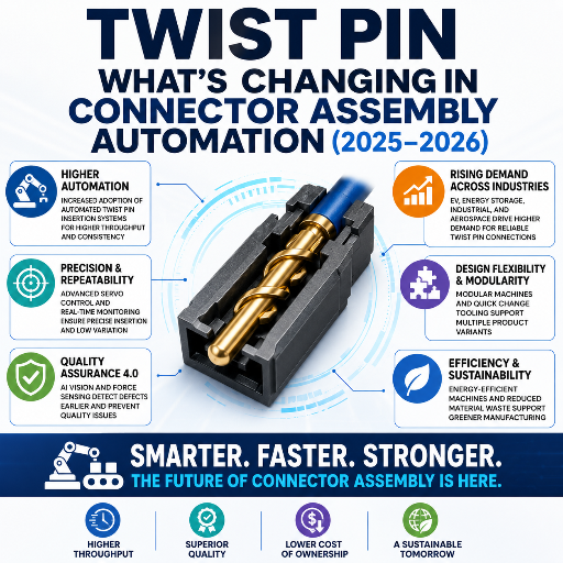
Three shifts should change how you spec a machine this year. First, demand: the broader connector market sits near $87 billion in 2025 and industry analyses project it past $160 billion by the mid-2030s at roughly 7% CAGR, pulled by EV wiring and electronics miniaturization, per connector market analysis. More connectors means more insertions, and steady pressure on both insertion capacity and line efficiency.
Second, technology. As of 2026, real-time process monitoring, predictive maintenance, and data analytics are becoming a standard expectation rather than a premium upgrade. In practical terms, force-monitoring and per-insertion data logging are crossing from “nice to have” to table-stakes — especially as miniaturized pins get smaller and shorter, which makes manual insertion harder and pushes cycle times up an estimated 20%.
Third, standards and traceability. Automotive and aerospace QA increasingly expect a data record per insertion, and acceptance is governed by living standards like IPC/WHMA-A-620. If you are planning a 2026 line, the action is concrete: require a machine that logs the force-vs-displacement signature per insertion and exports it. Buying purely on insertions-per-hour today risks owning a fast machine that cannot prove its own quality tomorrow.
Frequently Asked Questions
Is a connector “twist pin” the same as an upholstery twist pin?
View Answer
No. They share a name and nothing else. An upholstery twist pin is a coiled fastener for slipcovers. A connector twist pin is a hyperboloid contact — a basket of fine wires that grips the mating pin at many points, giving low insertion force and very high mating-cycle life. When you search for a twist pin & insulator insertion machine, you are in connector manufacturing, not furniture hardware, so filter your sources accordingly.
Should I buy a semi-automatic or a fully automatic pin insertion machine?
View Answer
It comes down to volume and mix. Fully automatic machines run 10,000–18,000 insertions per hour and pay back above roughly 500,000 insertions a month on a stable product. Semi-automatic machines run 1,500–5,000 per hour and win when your mix is wide and changeovers are frequent. If your work falls in regulated sectors, add a third filter — traceability — because that may force a force-monitored machine regardless of volume.
How is insertion force monitored, and why does it matter?
View Answer
A load cell in the insertion head records force against displacement for every stroke, producing a signature curve. A good insertion shows a lead-in, a ramp as the contact engages, and a plateau at seat depth. Under-insertion truncates the curve, a cracked insulator shows a sudden drop, and a bent pin spikes then collapses. Monitoring matters because it converts a hidden defect into a measurable pass/fail you can log — which is exactly what automotive and aerospace audits ask for.
Can stainless steel pins be inserted automatically?
View Answer
Yes, with care — stainless tends to gall. Generous lead-in chamfers, a slower press profile, and correct plating or lubricant prevent the gall-then-loosen failure that practitioners report. Always run a force-monitored sample batch first.
What standard governs pin and insulator insertion quality?
View Answer
For cable and wire assemblies, IPC/WHMA-A-620 is the common acceptance standard, and its current revision is the one to cite. For high-reliability and spaceflight work, NASA-STD-8739.4 covers contact preparation and installation into connectors, including crimp pull acceptance criteria. Press-fit connections also reference IEC 60352-5. Match your inspection to whichever your industry requires.
What’s the alternative for very high-volume insertion?
View Answer
For the highest volumes, the answer is parallelism and integration. Multi-pin heads insert up to 20 pins per cycle, and inline machines fold insertion into a larger automated PCB or wiring line with continuous feeding, placement, verification, and part handling. Some platforms are rated for tens of millions of insertions per year. Its trade-off is flexibility: the faster and more integrated the line, the more painful a connector change becomes — which loops back to why force-monitored, modular machines are the safer bet when your product roadmap is still moving.
Specifying a connector assembly line?
See configured options, force-monitoring, and changeover details on the ZEUEE solution page, or send your connector drawing for a sample run.
About This Analysis
This guide was compiled by ZEUEE’s engineering team from connector-assembly automation practice, public standards (IPC/WHMA-A-620, NASA-STD-8739.4, IEC 60352-5), granted press-fit insertion patents, and industry data on insertion throughput and the press-fit market. Where a number depends on your specific connector — hole tolerance, resin, pin alloy — we say so rather than imply a universal value; confirm critical figures against your datasheet and a monitored sample run.
References & Sources
- NASA-STD-8739.4, Workmanship Standard for Crimping and Interconnecting Cables and Wiring — NASA
- US Patent 11,211,760 — Stutter Step Press-Fit Connector Insertion Process — USPTO
- US Patent 11,424,562 — Press-Fit Insertion Method — USPTO
- IPC/WHMA-A-620, Requirements and Acceptance for Cable and Wire Assemblies — IPC
- Press-Fit Technology Roadmap — iNEMI (International Electronics Manufacturing Initiative)
- Hyperboloid Contact Technology Is Still Going Strong — Connector Supplier