Get in touch with Zeyu lntelligent Industrial Company
Updated June 2026 · Reviewed by the Shenzhen Zeyu Intelligent Industrial Science Technology Co., Ltd technical team
Pick the wrong barrel size by half a millimeter and a device run intermittently; reverse two wires and it dies on the bench. A DC Connector & Adapter Cable Line covers the plugs, jacks, and pre-terminated cables that deliver direct-current power to a device, and, for a manufacturer, the line that builds them at volume. This guide maps the connector families, the sizing and rating rules that actually govern fit and safety, and the assembly standards and processes that most buyer-facing guides skip.
In one paragraph: A DC connector is the interface that carries direct current from a source to a device through a defined contact geometry, a 5.5 mm × 2.1 mm barrel jack, a USB-C PD plug, an Anderson Powerpole, an MC4, or an XT60. Each is defined by physical size, voltage and current rating, and polarity. Get those three right and the connection is reliable; get the inner diameter or the polarity wrong and the device fail to start or is damaged. What sits behind the connector matter just as much: how the cable is terminated decides whether the joint survives years of vibration and heat.
Key takeaways
- The printed amp rating is a ceiling, not a working number, the real limit is heat at the contact, and the connector junction often fails before the wire does.
- Plug a 5.5 × 2.5 mm into a 5.5 × 2.1 mm jack and it fits but connects intermittently, inner diameter, not outer, is the usual culprit.
- Polarity has no universal standard; center-positive is common but not guaranteed, and reversing it usually kills the regulator first.
- IPC/WHMA-A-620 Class 3 does not use higher crimp pull-force than Class 2, the difference is inspection and traceability, not tension.
- About 90% of cable failures happen at the termination, which is why assembly method and strain relief decide field reliability.
Quick Specs: Common DC Connector Families
| Barrel / coaxial | 5–24 V, up to ~5 A (~120 W), usually center-positive |
| USB-C Power Delivery | 5/9/12/15/20 V (PD 3.1 adds 28/36/48 V), 100 W or 140–240 W EPR |
| Anderson Powerpole / SB | 12–48 V, 15–45 A (PP) up to 50–175 A (SB) |
| MC4 (solar) | 18–50 V per panel (string to 1500 V), 10–30 A |
| Governing assembly standard | IPC/WHMA-A-620 (Rev F, 2025), Class 1 / 2 / 3 |
DC Connector and Adapter Cable Types: The Full Family Map
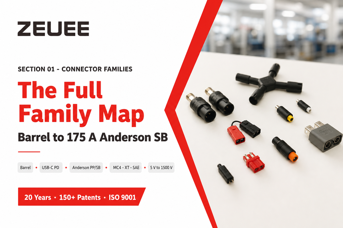
DC power moves through a handful of connector families, each tuned to a voltage and current band. Low-power electronics lean on coaxial barrel jacks and, increasingly, USB-C Power Delivery. Battery, solar, and mobility systems use keyed, high-current families such as Anderson Powerpole, MC4, and XT60/XT90. Anderson Powerpole connectors and MC4 connectors dominate battery systems and solar panels, while portable power stations mix barrel and USB inputs across 12V and 24V low-voltage rails. Below, the table maps the common families to the ratings that decide whether one fits your application. If you’re building these at scale rather than buying them, the same map drive connector assembly machine selection.
| Connector type | Typical voltage | Typical current | Common use |
|---|---|---|---|
| Coaxial barrel (e.g. 5.5×2.1 mm) | 5–24 V | ≤5 A | Routers, LED, instruments |
| USB-C PD | 5–48 V | 3–5 A | Laptops, phones, tools |
| Anderson Powerpole (PP15/30/45) | 12–48 V | 15–45 A | Ham radio, 12 V distribution |
| Anderson SB (SB50/120/175) | 12–48 V+ | 50–175 A | Forklifts, battery packs |
| MC4 | 18–50 V (string ≤1500 V) | 10–30 A | Solar PV strings |
| XT30 / XT60 / XT90 | 7–28 V | 30–90 A | RC, drones, battery |
| SAE 2-pin | 12–24 V | Moderate | Automotive, solar trickle |
| GX12 / GX16 / GX20 (aviation) | 12–48 V | By pin count | Panel-mount equipment |
| Automotive 12 V socket | 12–14.4 V (24–28 V trucks) | 10–15 A | Accessory power |
| D-Tap / P-Tap | Unregulated battery | Low | Cinema / camera rigs |
Ratings compiled from manufacturer datasheets and field data; treat them as typical bands, not guarantees for a specific part.
Two patterns matter for selection. First, raising system voltage is the cheapest way to cut current: the same power at 48 V draws a quarter of the current it would at 12 V, so cables and contacts shrink. Second, the family decides ease of assembly, barrel jacks and Powerpoles crimp quickly, while MC4 demands a calibrated die and a torque step. These are the main types of DC power connectors, and getting the connector types right means choosing the right DC connector by ratings, not by what happens to fit. Bench DC power supplies and field power systems both rely on the same matching discipline. Those assembly differences scale fast once you’re building thousands of units across the industries an automation line serves.
How to Read a DC Barrel Jack: The 4-Number Code
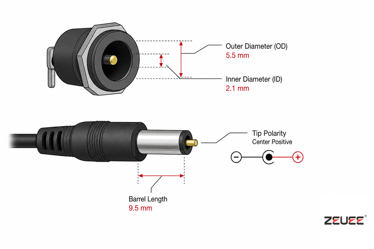
Every barrel jack is described by four numbers, outer diameter, inner diameter, length, and polarity, and missing any one of them is how the wrong part ends up in a box. Call it the 4-Number DC Barrel Code: OD × ID × length, plus tip polarity. By far the most common is the 5.5 mm OD with a 2.1 mm pin (the “DC5521”), but a 2.5 mm pin uses the same 5.5 mm shell.
There are two named standards behind these numbers, IEC 60130-10 and EIAJ RC-5320A, but neither is universal, so identical-looking plugs can carry different voltages.
| Barrel type | OD × ID (mm) | Typical voltage | Notes |
|---|---|---|---|
| DC5521 (IEC type A) | 5.5 × 2.1 | 9–24 V | Most common; center-positive |
| DC5525 | 5.5 × 2.5 | 12–19 V | Fits a 2.1 mm jack but intermittent |
| EIAJ-01 | 2.5 × 0.7 | 0–3.15 V | Micro devices |
| EIAJ-02 | 4.0 × 1.7 | 3.15–6.3 V | Small adapters |
| EIAJ-03 | ~4.75–5.0 × 1.7 | 6.3–10.5 V | Sources differ on OD |
| EIAJ-04 | 5.5 (internal pin) | 10.5–13.5 V | Has male center pin |
| EIAJ-05 | 6.5 (internal pin) | 13.5–18 V | Has male center pin |
| DC7909 (“8 mm”) | 7.9 × 0.9 | Power stations | “8 mm” hides 3 non-interchangeable sizes |
| Laptop pin-type (Dell/HP) | 7.4 × 5.0 + pin | 19–20 V | Center sense pin |
How to identify a DC connector size?
Measure the inner diameter first, because that’s the dimension that decides fit. Round toothpicks gauge roughly 2.1–2.2 mm and sit snug in a 2.1 mm jack but loose in a 2.5 mm one; a 5/64-inch (1.98 mm) drill shank enters a 2.1 mm pin while a 3/32-inch (2.38 mm) shank only enters a 2.5 mm one. Manufacturers hold tolerances near ±0.03–0.05 mm, so two sizes that differ by a hair are genuinely not interchangeable.
Calipers tend to read a round bore undersized, which is why pin gauges beat a quick measurement. On the device side, a DC power jack is the female connector, while the male plug and its center pin sit on the cable (male connectors mate into the jack). Common inner diameters are 2.0, 2.1mm, and 2.5 mm, and the molded housing keys each barrel plug to its jack.
💡 Field note
The most common service complaint — “it only works if I wiggle the plug” — is almost always a 2.5 mm pin in a 2.1 mm jack. Its outer shell mates, so it looks right, but the spring contact never seats on the undersized pin.
Voltage, Current, and Contact Resistance: The Contact-Resistance Heat Budget
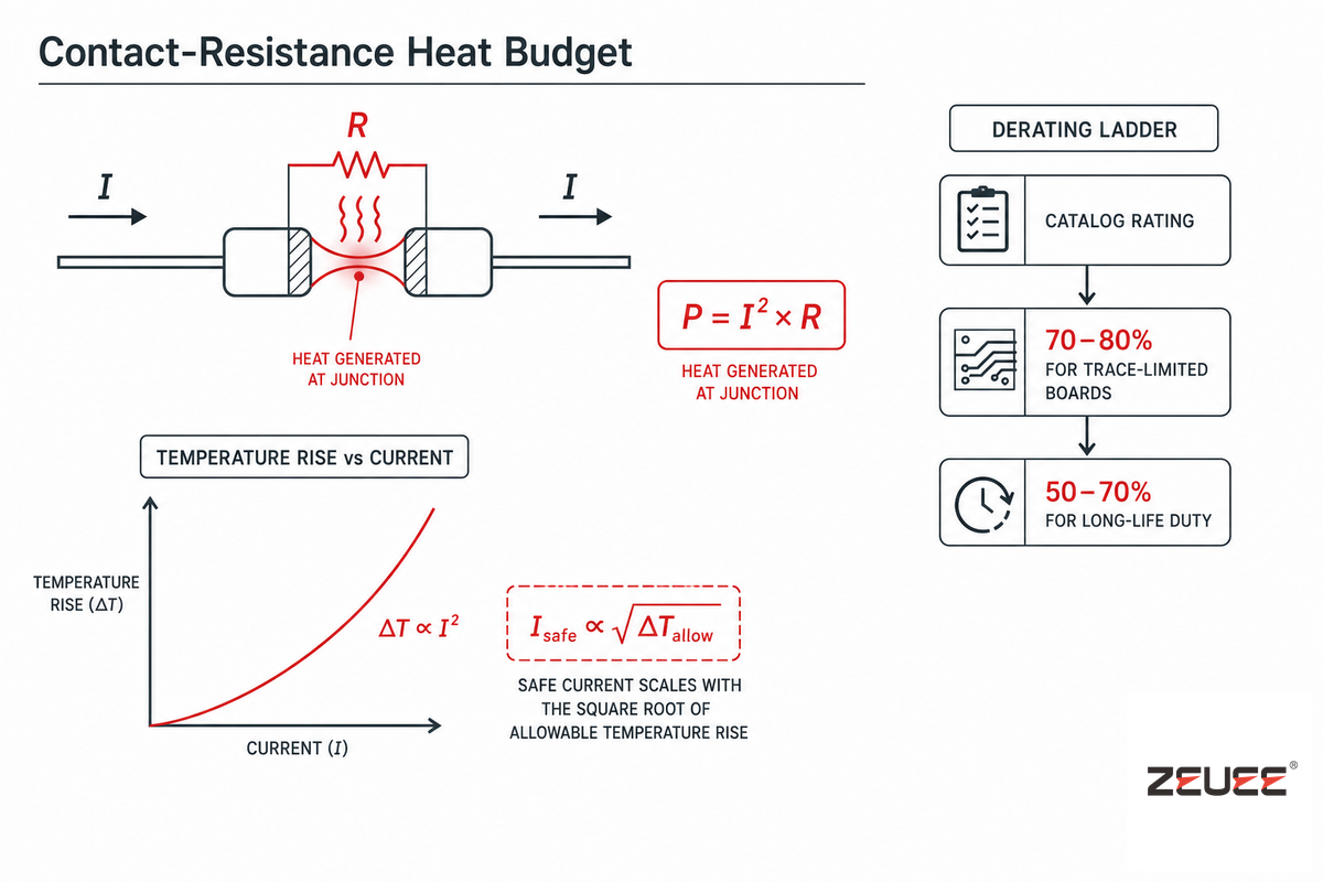
A connector’s printed amp rating is a test result under ideal conditions, not a working number you can lean on. That real ceiling is thermal, and the cleanest way to see it’s the Contact-Resistance Heat Budget: every contact dissipates power equal to current squared times its resistance (P = I²R). As connector engineers at Lumberg note, even a few milliohms of contact resistance produces noticeable heating once current climbs. Because heat rises with the square of current, the safe load scales with the square root of the allowable temperature rise, not linearly.
What makes a DC connector safe for high power?
Headroom at the contact, not a big number on the datasheet. Rated current comes from a temperature-rise test, usually current is raised until the hottest contact sit about 30 K above ambient. Use the square-root rule to re-rate it: a 12 A connector qualified at a 30 K rise, run to a tighter 25 K target, carries 12 × √(25/30) ≈ 10.95 A.
Real installations derate further, 70–80% of catalog for trace-limited boards, 50–70% for long-life automotive and industrial duty. For 20–500 A DC, a 200 A connector in a 60 °C enclosure should be planned around 140–160 A continuous.
Wire behind the connector has its own ceiling. Pairing copper wire gauge with current shows a large swing between in-conduit and free-air ampacity, the same 8 AWG copper carries 50 A in a raceway but 70 A in free air. Match the voltage and current to the wire: a 12V DC rail in automotive applications behaves differently from a 48 V battery bank, and electronic devices sharing one V DC line each add load. A peer-reviewed 2025 study in Applied Sciences measured a quieter variable: a rougher contact surface raised resistance and pushed temperature up faster, cutting allowable current, finish quality, not just plating, drives the budget.
| Copper AWG | In raceway, 75 °C | Free air, 75 °C | Breaker cap |
|---|---|---|---|
| 14 | 20 A | 30 A | 15 A |
| 12 | 25 A | 35 A | 20 A |
| 10 | 35 A | 50 A | 30 A |
| 8 | 50 A | 70 A | — |
| 6 | 65 A | 95 A | — |
| 4 | 85 A | 125 A | — |
Values assume a 30 °C ambient baseline; derate above that. Free-air column from NEC Table 310.17.
📐 Engineering Note
Published derating curves often sit about 20% below measured performance to cover measurement tolerance, not to give you a safety margin. Add your own guard band on top, a contact spring also weakens with insertion cycles, so a connector that runs at 52 °C at 5 A when new is safer planned at 3 A over its life.
Polarity and Wiring: The Polarity-First Principle
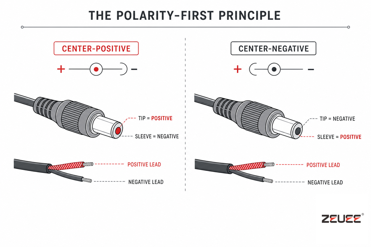
In DC connectors, polarity kills before current does. That’s the Polarity-First Principle: more devices die from a reversed center pin than from being slightly under-rated on amps, because there’s no universal polarity standard. Center-positive is the de facto norm for modern barrel devices, but guitar pedals, pre-2000 gear, and jacks that double as a battery-disconnect switch are routinely center-negative, a point ASME’s primer on AC and DC plugs underscores. Only measuring tells you for certain.
Which wire is positive on a DC adapter?
On a barrel adapter the tip is normally positive and the sleeve negative, but you should confirm it rather than assume. Look for the polarity symbol printed near the jack, a diagram showing whether the center or the outer ring carries the plus sign. With a multimeter on continuity, the negative barrel terminal is the one that read near zero ohms to the device’s ground plane or chassis.
On the cable itself, the conductor with a stripe, ridge, or printed marking is conventionally the positive lead, though that too is worth verifying before you power up.
⚠️ Important
A telltale of reversed polarity is a device that runs fine from USB but is dead from the barrel jack — the protection diode or voltage regulator usually fails first. If a second cable shares a common ground with the supply, reversed polarity can spread damage well beyond the local diode. Identify the positive and negative terminals first, since a connector is only used to connect or used to power a load safely once its polarity is verified.
AC-DC Adapter Cables and Cordsets: Matching Source to Device
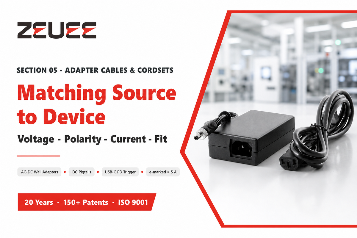
An adapter cable only works if four things line up: voltage, polarity, current headroom, and the connector itself. As ASME’s guide to power-adapter input and output plugs explains, AC-DC wall adapters and DC pigtails are the obvious cases, but the fast-growing one is the USB-C-to-barrel trigger cable, which negotiates a fixed voltage out of a USB-C PD source. Current is the catch: pulling the full 5 A (and 240 W) needs both a 100 W-plus PD source and an e-marked cable, without the e-marker, the cable caps at 3 A, and people then blame the barrel jack for the shortfall. Audio TRS plugs, despite fitting, aren’t a power connector; their exposed conductors short on insertion. Whether you’re using DC from a wall power adapter, a USB-to-DC lead, or a dc power cable off a bench supply, confirm whether the source is AC or DC and then match the voltage; in every setup a low-quality connector or the wrong power plug can starve a device that needs to get power cleanly.
✔ Check before you buy
- Output voltage matches device input exactly
- Polarity matches (tip-positive vs tip-negative)
- Current rating exceeds device draw with margin
- Plug OD and ID both match the jack
⚠ Common adapter mistakes
- Right connector, wrong voltage
- Right voltage, reversed polarity
- USB-C cable without an e-marker for 5 A
- 2.5 mm plug forced into a 2.1 mm jack
How DC Cables Are Assembled: The Crimp-Solder-Overmold Decision Triangle
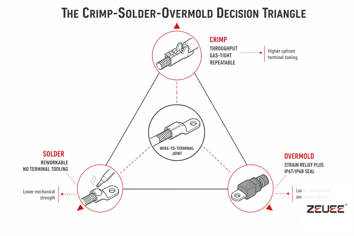
A connector is only as good as how the wire is attached to it, and roughly 90% of cable failures occur at that termination. Three methods dominate, and choosing among them is the Crimp-Solder-Overmold Decision Triangle: crimp for throughput and repeatability, solder for reworkability, and overmold for strain relief and sealing. Most production cables use a crimp as the electrical joint and an overmold as the mechanical and environmental jacket; solder fills the gaps where a crimp terminal isn’t available.
| Method | Strength | Weakness | A-620 chapter |
|---|---|---|---|
| Crimp | Gas-tight, fast, repeatable; locks out moisture | Needs calibrated die and pull testing | Ch. 5 |
| Solder | Reworkable; no terminal tooling | Wicking, cold joints, strain at the wick line | Ch. 4 |
| Overmold | Strain relief plus IP67/IP68 sealing | Tooling cost; material pair is critical | Ch. 10 |
Overmold is where good intentions go wrong. Matching overmold to jacket material (PVC on PVC, TPU on TPU) raises pull-force 30–50% through a chemical bond, while a mismatch can cut it 60–80% and let moisture in, so “overmolded” isn’t automatically rugged. A granted US patent, US 9,184,534 B1, even ties the overmold’s length to a fraction (45–50%) of the cable’s minimum bend radius. And a zip tie cinched behind a connector isn’t strain relief; its hard edge abrades through the jacket within a few hundred flex cycles.
“On a production line the crimp is where reliability is won or lost. We pull-test to the gauge minimum, monitor crimp force on every cycle, and treat a single severed strand as a reject, because the failure you cannot see in the factory is the one that comes back from the field.”
The Quality Standard Behind DC Cable Assemblies: IPC/WHMA-A-620
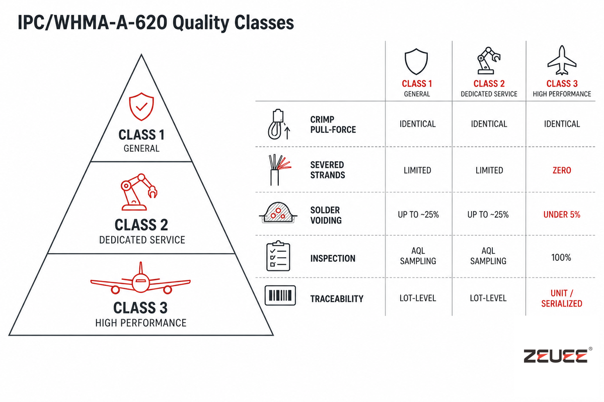
When a buyer asks whether a cable assembly is “good enough,” the answer live in one document: IPC/WHMA-A-620, the only industry-consensus standard for cable and wire assemblies. First published in 2002 and revised on a roughly three-year cadence, its current edition is Rev F (2025), which supersedes Rev E from October 2022. It defines three product classes by how much a failure cost.
| Criterion | Class 2 (Dedicated Service) | Class 3 (High Performance) |
|---|---|---|
| Crimp pull-force (Table 19-2) | Gauge minimum | Same gauge minimum |
| Severed conductor strands | Limited nicks allowed | Zero allowed |
| Solder-joint voiding | Up to ~25% | <5%, 360° fillet |
| Visual inspection | AQL sampling | 100% on critical features |
| Traceability | Lot-level | Unit-level / serialized |
Here’s the trade-off most buyers miss, and it cuts against intuition: the Table 19-2 crimp pull-force minimum is identical for Class 2 and Class 3. Stepping up to Class 3 doesn’t buy a tighter crimp, it buys 100% inspection instead of sampling, zero tolerance for strand damage, and serialized records, typically at a 15–30% cost premium per assembly. Class is assigned by you, the user, not by the inspector, and for Class 3 the record itself is part of the deliverable: a crimp isn’t Class 3 unless the test record exists and the tooling calibration matches the build date.
From Prototype to Production: Sourcing and Scaling Assembly

A handful of cables get built on a bench; thousands get built on a line. What pushes a shop from manual crimping to an automated DC connector and adapter cable assembly line is rarely the headline machine price. It’s the point where crimp repeatability and first-pass yield under A-620, plus labor cost, cross over the cost of the equipment. Crimping is also the step that benefit most from automation, because it moves the torque-critical, operator-sensitive process into a controlled factory environment with crimp-force monitoring on every cycle.
| Stage | Manual bench | Automated line |
|---|---|---|
| Cut & strip | Hand tool, operator-set length | Programmed cut/strip, length verified |
| Crimp | Hand crimper, periodic pull test | Applicator with crimp-force monitoring |
| Connector insert | Manual seating | Guided insertion, seat detection |
| Overmold | Outsourced or skipped | In-line injection |
| Test | Sample continuity check | 100% continuity + hipot gating |
If you’re evaluating that step, the questions to ask a builder are concrete: what’s the crimp-force monitoring resolution, is every assembly continuity- and hipot-tested, and which A-620 class does the line target by default. Done right, 100% continuity and hipot testing ensures long-term reliability in the field. ZEUEE has built whole-line solutions across precision electronics, automotive, and new-energy work, and the same logic that governs a barrel-jack cable scales to a multi-station line through automated test and continuity equipment and custom automation equipment built around the part.
Industry Outlook: High-Current DC, Electrification, and Automated Assembly
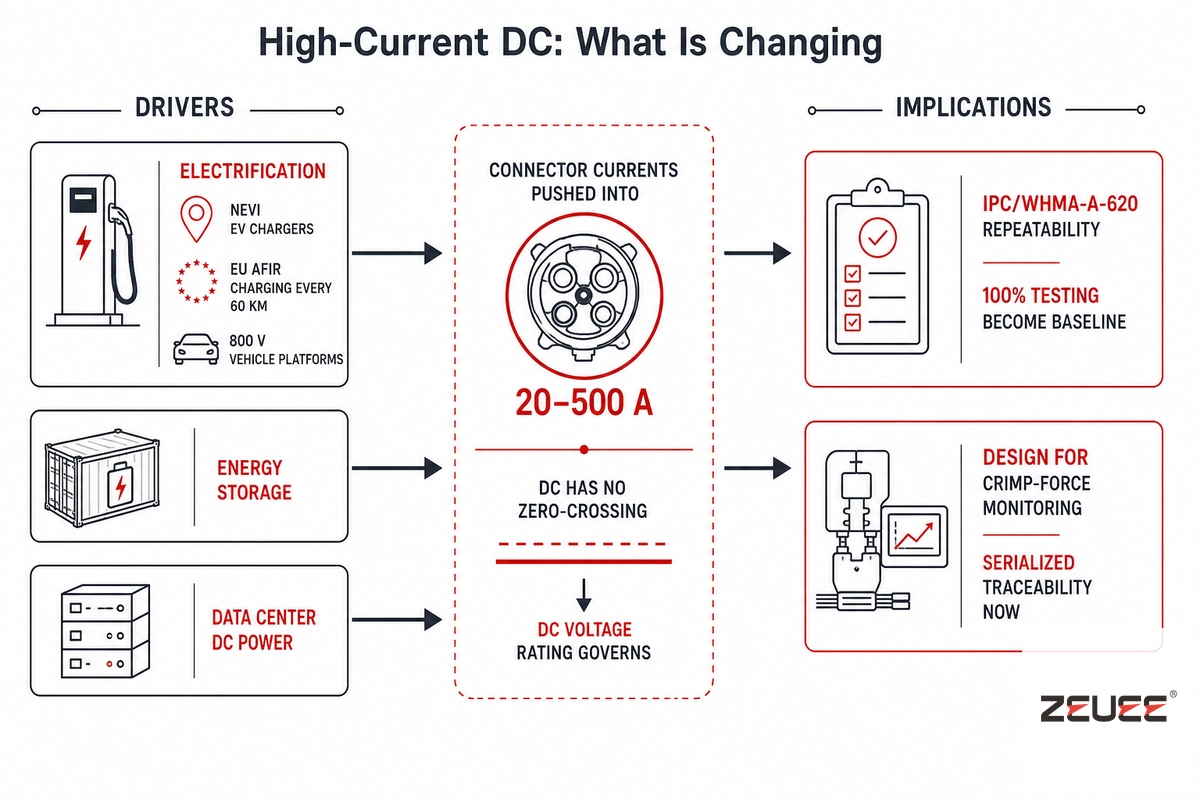
The center of gravity in DC connectors is shifting toward higher current, and that shift is driven by hard policy and physics rather than by market hype. Electrification is the engine: the US NEVI program committed up to $5 billion to EV chargers, the EU’s AFIR mandates a charging point every 60 km along its core network by 2025, and automakers are standardizing on 800 V platforms that push connector currents into the 20–500 A band. Energy storage and data-center power are pulling in the same direction, and DC is harder on a contact than AC because there’s no zero-crossing to extinguish the arc when you disconnect under load, so the connector’s DC voltage rating, not its AC rating, governs.
For buyers, the practical consequence is that the assembly bar is rising with the current. A loose crimp that was tolerable at 5 A becomes a hot spot at 150 A, which is why A-620 repeatability and 100% testing are moving from “nice to have” to baseline. As a directional backdrop, the broader AC-DC cable assembly market is projected to grow at roughly 6.8% a year through 2035, and the International Energy Agency reported electricity demand rose 4.3% in 2024, useful context, but the decision driver is the current band you’re designing for, not the size of the market. If you’re planning a 2026 line for higher-current DC products, build for crimp-force monitoring and serialized traceability now rather than retrofitting them later.
Frequently Asked Questions
What is the difference between a DC connector and an adapter cable?
View Answer
A DC connector is the plug or jack itself, the contact geometry that mates and carries current, such as a barrel jack, an MC4, or an XT60. An adapter cable is the assembled wire with connectors terminated on each end, often converting one interface to another, for example a USB-C PD source to a barrel jack.
Each connector defines fit and rating; the adapter cable defines what connects to what, and how reliably the joint behind it survives use. In short, the connector is the part and the adapter cable is the finished assembly.
How do I identify the size of a DC barrel connector?
View Answer
Measure inner diameter, outer diameter, and length, then confirm polarity. Most common is a 5.5 mm OD with a 2.1 mm pin, but 2.5 mm pins share the same shell. A 5/64-inch drill shank enters a 2.1 mm pin; a 3/32-inch shank only enters a 2.5 mm one. Because tolerances run near ±0.05 mm, pin gauges are more reliable than calipers, which read round bores undersized.
Which wire is positive on a DC adapter?
View Answer
On a barrel plug the tip is usually positive and the sleeve negative, but there’s no universal standard, so verify it. On the cable, the striped or ridged conductor is conventionally positive; the polarity symbol near the jack show which terminal carries the plus sign. With a multimeter, the negative terminal read near zero ohms to the device chassis. Devices with center-negative jacks include many guitar pedals and older equipment.
Is crimping or soldering better for DC connectors?
View Answer
For production, a properly tooled crimp wins: it forms a gas-tight joint, runs fast, and is repeatable. Solder suits low-volume rework and terminals that have no crimp option, but it risks wicking and strain cracking. For volume production, a monitored crimp win.
What is IPC/WHMA-A-620 and why does it matter?
View Answer
IPC/WHMA-A-620 is the industry-consensus standard for cable and wire-assembly acceptance, currently at Rev F (2025). It defines three quality classes and the accept-reject criteria for crimps, solder joints, and strain relief. It matters because it gives buyers and builders a shared, auditable definition of “acceptable,” so a Class 3 cable means the same thing across suppliers.
Can I use any DC connector with my power supply?
View Answer
No. Connectors must match voltage, current, polarity, and physical size. Even a plug that fit mechanically can be wrong on polarity or under-rated on current, and either mistake can damage the device. Always confirm all four, size, voltage, current, and polarity, before you apply power.
Building DC connector and adapter cables at volume?
See how an automated DC connector & adapter cable line crimps, overmolds, and 100%-tests to IPC/WHMA-A-620.
About This Guide
This guide draws on the published connector standards (IEC 60130-10, EIAJ RC-5320A, IPC/WHMA-A-620 Rev F) and on ZEUEE’s own experience building DC connector and adapter cable assembly lines for precision electronics, automotive, and new-energy customers since 2005. Where field figures vary by part and installation, barrel current limits, derating, crimp pull-force, we have framed them as bands rather than fixed values. Reviewed by the Shenzhen Zeyu Intelligent Industrial Science Technology Co., Ltd technical team.
References & Sources
- IPC/WHMA-A-620F-2025: Requirements and Acceptance for Cable and Wire Assemblies, ANSI / IPC
- Coaxial power connector (IEC 60130-10, EIAJ RC-5320A sizing), Wikipedia
- Contact Resistance and Temperature Rise vs Surface Finish (Applied Sciences, 2025), MDPI peer-reviewed
- US 9,184,534 B1: Over-mold strain relief for an electrical power connector, USPTO
- The Difference Between AC and DC Plugs and Power Connectors, ASME
- IPC/WHMA-A-620 Gets an Update, ASSEMBLY Magazine
- Electricity demand and electrification data, International Energy Agency