Get in touch with Zeyu lntelligent Industrial Company
Automated Testing Equipment: How It Works, the Main Types, and How to Choose
updated june 2026. reviewed by the ZEUEE team.
– equipment for automation and for manufacturing automated testing equipment is the quiet difference between a line that ships clean boards and one that ships field returns. this guide e×plains what automated testing equipment is, how an ATE system actually works, the main test methods and where each one wins, and how to choose and budget for the right approach-without the vendor pitch. If you already know you need a custom test cell built around your part, the automated testing equipment ZEUEE designs and builds is the place to start; if you are still mapping the landscape, read on.
– definition of automated testing equipment in short: automated testing equipment (ATE) is a computer-controlled system that automatically measures and verifies an electronic component, board, or assembly-the device under test (DUT)-against a pass/fail specification, using test instruments, switching, a fi×ture, and test-e×ecutive software. It replaces manual probing with repeatable, high-speed measurement so manufacturers can find faults before a product reaches the customer.
Automated Testing Equipment at a Glance
| What it is | Computer-controlled system that tests a DUT (device under test) automatically |
| Where it runs | Component → board (PCBA) → module / system → final / end-of-line test |
| Coverage measured in | Fault coverage % + defects per million (DPPM) |
| Core methods | ICT, functional test, flying probe, AOI, AXI, boundary scan, burn-in, HIL, wafer / semiconductor test |
| Cost model | Fi×ture + test program (NRE) + instruments + per-unit test time |
| Key standards | IEEE 1149.1 (boundary scan), IPC-9252, IPC-A-610J |
Key takeaways
- – automated testing equipment options there is no single “best” automated testing equipment method-coverage leadership shifts with board volume, component density, and test-point access.
- – the 5 building blocks of a automated testing system an ATE system is five building blocks: instruments, switching, fixture, test software, and a controller-the test program, not the box, is the real project.
- – cost of quality in manufacturing the defect costs roughly 1x at component test, 10x at board/end-of-line, and 100x in the field-the cost-of-quality math that justifies test.
- – hardware automated testing equipment is not software test automation, this guide is about the physical equipment that tests electronics.
What Is Automated Testing Equipment?
– definitions automated testing equipment (ATE) is any computer-controlled apparatus that performs tests on a device under test-also called the unit under test (UUT) or equipment under test-using automation to quickly take measurements and evaluate the results against a performance and quality specification.
In other words, ATE automates the measurement work a technician would otherwise do by hand, so a plant can automate the testing of electronic devices and systems at production speed. An ATE setup can be as simple as a computer-controlled digital multimeter or as involved as a system of dozens of synchronized test instruments, as the reference definition on automatic test equipment describes. What ties them together is that the equipment-not a technician-applies the stimulus and judges pass or fail.
fundamentally ATE, then, is hardware and software collaborating on the task: the instrumentation outputs the stimuli, measuring them, and returns their judgment by means of its built-in limits the software. (Heajageg Vijifak components and system after assembly, and also during electronics manufacturing.) It perform the same function for integrated circuits and printed circuit boards, it verifies automotive avionics and modules (the module on a car’s instrument panel) , it checks the hard disks in and consumer electronics. For this matter it tests newly introduced semiconductor devices-and indeed, on line checking every die before packaging, -an d allows unattended testing of several pieces of electronics simultaneosuly, and when it gets into military or the “military” industries (also called the “aerospace and defense’ “industries), and checks aircraft radar and avionics, as well as wireless communicatio hardware. Through this breadth of applications, automation provides what man is incapable of delivering: speed, “repeatability,” and traceable test information.
⚠️ One thing to clear up first
automated testing hardware (hardware ATE) and test automation software (automated software QA based on Selenium and Python) has just the name in common. This documentation only concerns the physical devices and test rigs that the electronics use. If you came here in search of unit test frameworks, this is not the appropriate type of test automation.
How Automated Test Equipment Works: The 5 Building Blocks
All ATE systems are the same-a benchtop rig up to semiconductor test floor. An ATE is a stack of electronic test equipment (test and measurement instruments) that a team of engineers puts together and makes software perform test sequence steps. It helps if you know the blocks to quickly review a quote and understand the hardware costs.
- Test Equipment – these instruments – sources and meters – drive and measure the device under test (DUT): The equipment often used are some variety of arbitary-waveform signal generator (generator), a power supplies (fully programmable) , a 6 ½-digit DVM, a scope or digitizer(most are about 100 MHz to 1 GHz) and maybe analog and/or RF instrumentation, these take measurements.
- Switching/matrix A high-speed switching system which is able to send many instrument to a selection of test points whereby single instrument is accessible from hundreds of nodes/DUTs.
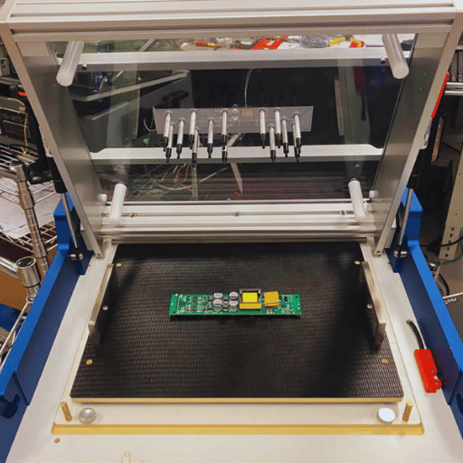
- DUT interface / fixture – Thephysical connection point to the DUT A bed of nails fixture, a flying probe, a Handler for packaged parts, or a wafer prober (for bare die), this connects through an Interface test adapter (ITA). The test probes plus the fixture establish what the system can reach in the first place.
- The Test Executive The software component that defines each measurement that is taken, how it will be tested (the pass/fail limits) and is typically comprised of the sequence or script in a programming environment (LabVIEW, Python, C, or test executive software such as TestStand). This programmability provides test sequencing functionality and transforms individual instrument instruments into an integrated system.
- Controller and data layer: An industrial PC, the glue that holds all parts together, and the data-acquisition line logging output results, often as STDF, for analysis.
These devices communicate with the controller on an instrument bus. For decades the primary choices have been GPIB, PXI, VXI, and LXI.GPIB, which transmits at more than 8 MB/s and supports 14 chained instruments, still finds favor with some users for its high bus bandwidth and the ability to link multiple instruments via a daisy-chain arrangement. Which bus you choose influences the number of channels you have, the speed of data transfers and how you scale.
📐 Engineering Note
In any low-resistance or high-current measurement, connect fixture for 4-wire (Kelvin)sensing,not 2-wire. At50 m and 1 A with 100 m of lead-and-contact resistance, real 50 mV is displayed as 150 mV – 3 error, falsely rejecting the part. How good is the contact?
Most test headaches lie in this arena, not in instrument accuracy.
What are the components of an ATE system?
An ATE system comprises a test set (instruments for generating signals-sources-and for measuring voltages-meters); a switching system to apply the test set to the device under test (DUT); a DUT test head or “handle” or “Zafi mipr”; test executive SW; and a data-log layered controller. The test set of a semiconductor ATE includes Jupihr, which is an individual devices Jupi her Dini, Par measurement units, arbitrary waveform generator digitizers and others; and this instrument set is timed under the control of the controller; to correctly activate the source at the right time; and measure in time with source activation. This system scales up to suit any number of channels from a single instrument bench top to multiple sites, test many DUTs at once in parallel.
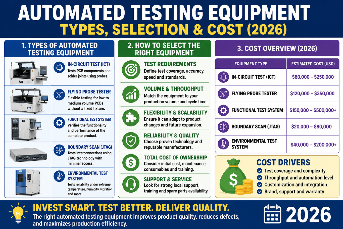
The Main Types of Automated Testing Equipment
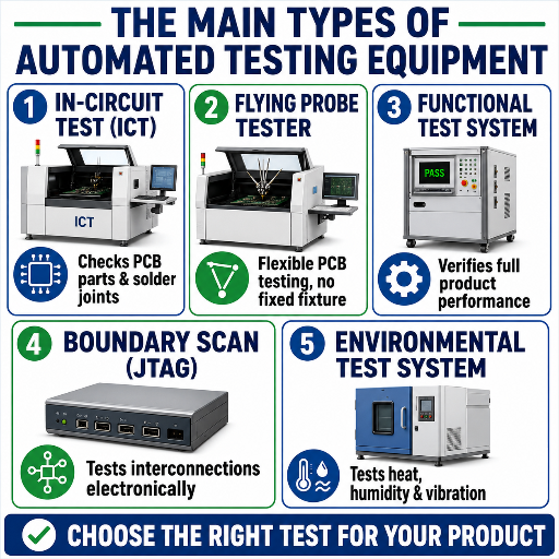
The tag “automated testing equipment” encompasses a family of methods, addressing various defects in specific stages along the manufacturing process. The following tree displays The Test-Method Family Tree, mapping out ten methods to what they check for, at what point in the line, and their detection capabilities: – a routing guide for the defect you care most about and where to locate the method that can find it.
| Method | What it verifies | Where in line | Fixture / interface | Catches |
|---|---|---|---|---|
| In-circuit test (ICT) | Each component’s presence, value, orientation | Post-assembly (PCBA) | Bed-of-nails | Shorts, opens, wrong/missing parts |
| Manufacturing defect analyzer (MDA) | Unpowered structural defects | Post-assembly | Bed-of-nails | Shorts, opens, gross value errors |
| Flying probe test | Structural integrity, fixtureless | Prototype to mid-volume | Moving probes | Shorts, opens, value, polarity |
| Functional test (FCT) | Does the board do its job? | End-of-line / final test | Custom test fixture | Behavioral / system faults |
| Boundary scan (JTAG) | Digital interconnect via chip pins | Post-assembly, no physical probe | JTAG TAP port | Opens/shorts on dense BGAs |
| Automated optical inspection (AOI) | Visible solder & placement | Post-paste / post-reflow | Camera (non-contact) | Missing parts, bridges, tombstones |
| Automated X-ray inspection (AXI) | Hidden solder joints (BGA) | Post-reflow | X-ray (non-contact) | Voids, hidden opens under BGAs |
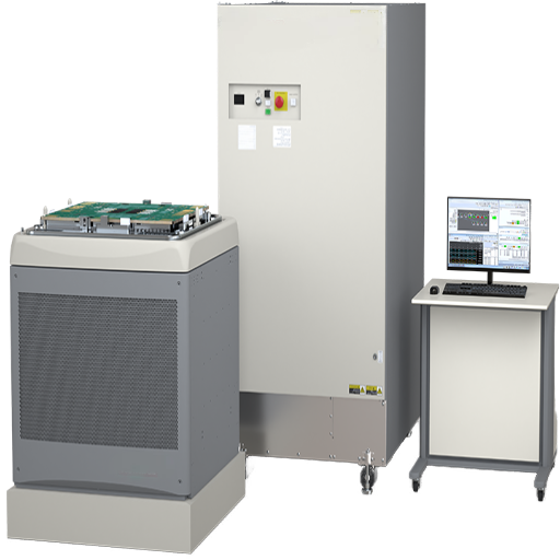
| Burn-in / reliability | Survival under stress | Pre-shipment screen | Burn-in board / chamber | Infant-mortality failures |
| Hardware-in-the-loop (HIL) | Embedded module vs. simulated world | Module / system validation | Real-time simulator | Control-logic & firmware faults |
| Semiconductor / wafer test | IC parametric & functional | Wafer & final (packaged) | Probe card / handler | Die defects before packaging |
Method definitions extracted from IEEE 1149.1 (boundary scan) standard, IPC structure-test guide lines and electronics manufacturing references.
Burn-in is the odd one out as far as cost-it exercises parts at a very high temperature-usually ranging from 40° C to 125 C -to screen for infant failures, hence it’s usually used for safety/high-reliability parts, not the whole board.
What are examples of automated testing equipment?
Typical equipment include automated testing’s in-circuit Testers (ICT) and manufacturing defect analyzers, flying-probe Testers, functional test (FCT) stations, boundary-scan/JTAG controllers, automated AOI and automated AXI machines, burn-in systems, Hardware-In-The-Loop (HIL) rigs and semiconductor wafer probers and final-test handlers. Most production lines use a combination of two or three – e.g. AOI after reflow then ICT or flying probe for structure then functional test at end of line.
In-Circuit vs Functional vs Flying Probe: Choosing a Test Method
The one assumption to kill here is that the in-circuit circuit test is always your best option. it isn’t. ICT, flying probe and functional test go toe-to-toe based on volumes, component densities and the simple fact that you have to access the test points at all. According to Keysight, the flying probe might not achieve higher fault coverage then the classic, and isn’t best for prototypes or low volume run tests whereas the in-circuit test might not provide a good electrical contact for higher density surface-mount boards where there simply isn’t enough space for probe/pad interface – when does bed-of-nails fail as access becomes compromised by dense boards?
It is why testers debate among themselves whether they are seeing the death of the old school ICT tests.
✔ In-circuit test (bed-of-nails)
- High structural coverage, fast per board (often 10–60 s)
- Needs test-point access + a fixture (high NRE)
- Wins at high, stable volume
⚠ Flying probe
- No fixture, near-zero NRE, fast to program
- Slow per board (minutes), not for high volume
- Wins at prototype / low-to-mid volume + high mix
✔ Functional test (FCT)
- Proves the board actually works
- Lower structural-defect coverage than ICT; slower
- The end-of-line safety net
Only one number dictates the battle of ICT versus Flying probe, known to me as The Fixture-Cost Crossover. In dollar terms it’s only about the slope of a single line — in a nail-bed fixture that up front cost of doing business you amortize over the volume, whereas in Flying probe it’s a zero up front cost, but you pay with time board-after-board.
Worked Example (numbers are typical for this field: tailor them to your fixture quote and your labor rate):
At 200 boards / yr.
– just the $15,000 ICT fixture is ~$75 /board – the flying probe with no fixture but 5 minutes per board at a $60/ hour cell is ~ $5 per flying probe win. The crossover point At 50,000 boards per year, that same $15,000 ICT fixture costs $0.30 / board, and a 20 second ICT ( $.33/board) easily beats the $5 flying probe ICT win. At 5000 or more boards per year, get the fixture, anything less, build without.
The ICT-or-Functional Decision Tree
- Are volumes greater than low thousands annually and is the design stable?If not, then no flying probe (no fixture to amortise)
- Can you access probe-able test points on an not-so ultra dense board?I.e no Boundary Scan and Flying probe (access through Bed-of-nails not found).
- If there’s firmware/system behavior of the product that structure test alone cannot demonstrate, add functional test to the end of the line after structural test.
- Need a hidden bga? AXI. Only visible solder?AOIafter the reflow.
How to Choose an Automated Test System: 7 Selection Factors
After you decide the methodology, selecting the automated test system is then determined by a “big 7” factors, apply these to an RFQ and you can compare apples to apples, no black box for your supplierQuotes that are provided can also be analyzed by using these “big 7” so that all apples are alike.ModularATE and SW Test solutions scales far better than the fixed rig with your products changing.
- ✔Fault-coverage target — what percentage of likely defects must the system catch, and how is that coverage proven?
- ✔Throughput and cycle time — the takt target sets the architecture; a shorter test time may force servo handling and parallel multi-site testing.
- ✔Product mix and changeover — one product or twenty? High mix rewards reconfigurable fixturing and a modular ATE platform.
- ✔Fixturing strategy — bed-of-nails, flying probe, or handler, decided by the Fixture-Cost Crossover above.
- ✔Test program and NRE — the test program is the real deliverable; budget the engineering to write and debug it, not just the hardware.
- ✔Scalability and upgrade path — can you add channels or instruments without replacing the system? Modular, software-reconfigurable platforms age better.
- Does it log per-part test data (STDF) into your MES for yield analysis and audits?
What’s missing from that list?
Price. Cheapest upfront price is often most expensive in test, because software and support cost real money far beyond the quote.
The Real Cost of Test: Why Automated Testing Pays Back
Test isn’t a tax-it’s insurance that can pay off.
The reason ATE can really pay for itself, is the cost-of-quality cascade. Lowest possible spot to catch a defect: earliest possible spot.
The 1-10-100 Test-Escape Cascade
Catch at incoming component test: $1 of effort for the scrap or swap.
Catch at board or in-line functional test, and the cost escalates to 10x (diagnosis, rework, retest). Catch at field failure (return or field service call) and the cost is 100x+ (at a minimum). (Note: the scale factors above are illustrative, not absolute laws-NIST, for instance, has produced models that vary with component lifecycle from roughly 1x (design) to 30x (field failure), but they demonstrate the general principle that justifies the cell.)
Cost-of-Quality Example For a 10,000-part production run with an end-of-line test escape rate of 0.5%, 50 units contain a latent flaw. If caught at end-of-line test ($10/unit), it costs roughly $500 to recover those units.
If that same defect gets into the field ($100+/unit including service calls, recalls, lost productivity, brand impact), that 50-unit escape costs over $5,000 or a $5,000+, a 10x increase from that single production run. Given that even in high volume, typical inline detection rates are over 95%, those cost-of-quality dollars rarely have a chance to spill into the field, which in turn lifts first-pass yields from, for example, 95% toward 99%.
How the 7 Levers Control Your Cost of Test What factors are we discussing beyond sticker price to account for your cost of test cell?
These are controlled through 7 critical parameters described in the model below.
| Lever | Drives |
|---|---|
| Fixture | Upfront NRE; amortized over volume |
| Test program (NRE) | Engineering hours to write + debug |
| Instruments | Capital; accuracy and channel count |
| Throughput | Per-unit test time × volume |
| Coverage depth | More coverage = more test time + program |
| Uptime | Calibration, maintenance, spares |
| Rework avoided | The return side of the ledger (escapes prevented) |
Here again, testing ceases to be just a button push and starts becoming a judgment-as the authoritative textbook literature on ATE suggests, “inexpensive electronic devices are seldom tested fully, while high-yield, medical-grade and reliability test components are tested much more extensively.” So you’ll begin to understand that testing has become an exercise in optimizing test for the appropriate cost/yield tradeoff.
Standards and Compliance for Automated Test
The standards on which automated’s electronic test offerings are based are your key for distinguishing true test partners from reseller brokers.
Below are the “go-to” standard requirements of 2026.
- IEEE 1149.1 – This is the Test Access Port and Boundary-Scan Architecture standard, often cited in FAA guidance as the standard on which tests like boundary scan is performed. Note: Although the 2013 revision of this standard carries an “inactive-reserved” designation from the IEEE SA, it remains the pervasive and accepted boundary scan reference standard; see its companion standards for boundary scan on analog and embedded instruments (IEEE 1687/IJTAG).
- IPC-A-610J (2024), which is the 2024 revision of the most widely utilized guide line as for what a “good” solder joint and assembly looks like. IPC has also released a new “J” revision of the IPC J-STD-001 (solder process control), and the IPC A-610 (acceptance standard).
- IPC-9252 — guidance for electrical test of unpopulated boards.
- IATF 16949:2016-the automotive quality-management standard; its certification scheme, IATF Rules 6th Edition, went into effect January 1, 2025, pushing lines to 100% on-line testing, the rules’ new traceable requirement.
- In addition to the defence (and currently only aerospace programs) requirement electronics standard adds traceability on per-part and verification for AS9100 (aerospace) and Vahevig Rovenor (medical devices).
In practice a test plan that states the relevant standard in your industry – and provides coverage against it – is worth much more than one that merely promises to deliver quality.
Design for Test: Fixtures, Test Points, and Avoiding False Fails
“Many of the worst test problems occur long before the first board ever gets constructed. Design for test,” a field of activity which NASA’s Jet Propulsion Laboratory is formalizing as practice for boundary scan and beyond, “is really an effort to keep the board addressable and to make sure the information that you get is valid. We see three main failure modes in the field:
⚠️ Common mistakes that wreck test results
- Test-point access gaps. Increasing density leaves no room to land a probe; bed-of-nails coverage fails and you are stuck with boundary scan or believe blind nodes. A typical DFT command is a padprobe-able of minimum 0.9 mm – plan them in the layout!
- False fails. Boards good enough in manufacturing that fail at test-often a test fixture fixture error, a poorly set test limit, or an incorrectly planned and programmed step-subvert yield and build skepticism. A test fails for the right reason when good boards still do.A board that fails for the wrong reason is more dangerous than no test at all because operators lose respect and begin dismissing test failures. Just as bad is moving too aggressively to eliminate false positive calls in a camera orAO I inspection, and then passing defective boards (in medical and safety fields especially, the decision to allow a certain rate of passes and failsis a conscious one).
- No correlation/Weak correlation or gauge repeatability The test is set up for boards to pass one day and fail the next which means it’s the board not the measurement system which is at fault. You need to prove a system can repeat and pass identical board day after day.
Diagnostics is the tough half of ATE: a failed-tester doesn’t help unless you know the right suspect. Signature analysis by analog and flying-probe follow-up reduce a board-level failure down to an ambiguity group to keep rework costs down.
Implementing ATE on Your Line: Integration, FAT, and Traceability
Once a methodology is selected the progression to a test cell is well defined, it begins with a definition of the DUT and desired coverage. Test program creation, test hardware development and validation, a test cell FAT prior to ship and subsequent implementation of the handler and data interface, followed by a ramp. Because a hardware cell includes presses, handlers, and moving Zafigrips, operator safety MUST be an early concern as is noted in OSHA 29 CFR 1910.212 which mandate guarding of point-of-operation hazards, nip point hazards and rotating equipment; Safety guards, electronic and physical, are intrinsic elements of compliant stations, not add-on items.
What purchasers misunderstand is that for test programmers the position is defined as writing software for station control and selecting and purchasing the proper instrument, not just attaching the station hardware and saying that test is done.
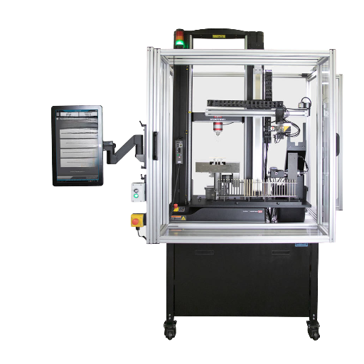
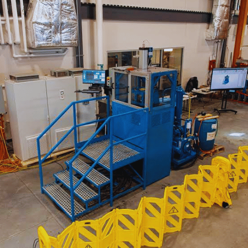
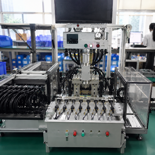
For our in-house builds, a two-part decision determines if a line escapes or ships them. For one, we hardwire CCD visual inspection and electrical test onto each station; we don’t use sampled end-of-line testing – a sample batch could overlook the critical defect. Second, we ensure traceability at the part, not lot, level, so a call from the field identifies a single serialized unit and its test history.
On our connector-mating and pin-insertion stations, we use CCD for 0.1 mm- class placement with 0.4 mm-pitch components, hold station repeatability within ± 0.02 mm, and reject crimps the instant pull- force dips about 5% below spec. Each machine is factory verified prior to shipment with in-house remote diagnostics and spared parts – a logical decision when building equipment for more than 30 countries.
“The machine must justify each cycle, not just do one fast one. Which is why we build the CCD inspection into the station as it is made, and it’s not an attachment we’ll stick on. Traceability is not batch – it’s per part.”
The automated testing line of test cells sits with connector and automated machines which fill the line, and can be plugged into automation for end-to-end production. If you’re building test equipment around particular assemblies, these machines fit in beside your connector/automated building lines.
The Outlook: Where Automated Testing Equipment Is Heading
Three trends are dictating future buying decisions, and none of them include the phrase “the market is growing.” The first: The refactoring of electronics operations. Lines are coming back to locations where they had been contract-manufactured in the past. Those locations now require their own test operations rather than the contract manufacturer’s test resources.
Second, increasing product complexity, the silent killer, provides the second, less shouted story. As packaging gets tighter, the I/O count grows higher and the test platforms slide down toward 3 nm class, physical access to probe becomes smaller and the need for coverage shifts to the boundary scan domain over the familiar bed-of-nails ICT and boundary scan access and flying probe as the key method. Thirdly, Zero Defect/Traceability as is occurring in both the automotive space and under AS9100 within aerospace with requirements associated with 16949 due in 2025 are all making what was once a sampled measurement a 100 percent in-line measure with part by part reporting.
Beyond all that, the AI/ml assist is being used for defect classification on AOI and x-ray test, and patent filings have highlighted modular, scaled, and multi-domain testers-including ones testing both electrical and optical features together in a single pass. Just to add context: industry analysts put the ATE market in the high single-digit billions of dollars globally and project it’ll be in the low teens of billions of dollars by early 2030-so if you see that, file it under “context,” not “buy now.” You should be guided by your roadmap instead: If you know your 2026 line will incorporate denser boards, and/or someEV/battery modules, you’ll be smart to plan-in your layout design, before the board layout is final, as this is a vastly cheaper proposition than fixing things after the fact-for sufficient test access including for Boundary Scan or functionally-related techniques now.
Frequently Asked Questions
Q: What is automated testing equipment (ATE)?
View Answer
Automated testing equipment is a computer-controlled system that automatically tests an electronic device under test (DUT) — a component, board, or assembly — against a pass/fail specification. It applies signals through test instruments, captures the responses, and judges the result without a technician taking each measurement. ATE ranges from a single computer-controlled multimeter to a multi-instrument system that tests many devices in parallel, and it is used across electronics manufacturing, semiconductor, automotive, and aerospace production.
Q: What are examples of automated testing equipment?
View Answer
Common examples are in-circuit testers (ICT) and bed-of-nails systems, flying-probe testers, functional test (FCT) stations, boundary-scan/JTAG controllers, automated optical inspection (AOI) and automated X-ray inspection (AXI) machines, burn-in chambers, hardware-in-the-loop (HIL) rigs, and semiconductor wafer probers and final-test handlers. A typical surface-mount line runs several in sequence — AOI after reflow for visible defects, ICT or flying probe for structure, and functional test at end of line to prove the product works.
Q: What is the difference between in-circuit test and functional test?
View Answer
In-circuit test (ICT) checks the board’s structure — is every component present, the right value, and correctly oriented, with no shorts or opens — usually through a bed-of-nails fixture. Functional test (FCT) checks behavior: does the finished board actually do its job when powered and exercised like the real product? ICT generally gives higher structural-defect coverage and runs faster per board, while FCT catches system-level and firmware faults that structure alone cannot. Most lines use both: ICT or flying probe for structure, then functional test as the end-of-line safety net.
Q: How much does automated test equipment cost?
View Answer
There is no single price, because the cost of automated test equipment is driven by seven levers, not a sticker: the fixture (a bed-of-nails fixture is a real upfront NRE; flying probe needs none), the test program (engineering hours to write and debug it — often the largest hidden cost), the instruments and their accuracy and channel count, the throughput target, how deep the coverage must go, ongoing uptime costs like calibration and spares, and the rework the system prevents. A useful way to size it is to compare the test-cell investment against the cost-of-quality cascade: if your escape rate times field-failure cost exceeds the amortized cost of the cell, the test pays for itself. Quote against those levers, not against the lowest headline number, or you will buy the cheapest system and the highest total cost of ownership.
Q: Is ATE the same as software test automation?
View Answer
No. Hardware ATE tests physical electronics; software test automation (tools like Selenium) tests code. They share a name but solve different problems.
Q: What standards apply to automated electronic testing?
View Answer
Boundary scan follows IEEE 1149.1; board test and acceptance follow IPC-9252 and IPC-A-610J (2024), with soldering under IPC J-STD-001. Sector quality systems add requirements: IATF 16949 (automotive, 6th-edition rules effective 2025), AS9100 (aerospace), and ISO 13485 (medical devices), all of which lean on per-part traceability.
Q: When should I choose flying probe over a bed-of-nails fixture?
View Answer
Choose flying probe for prototypes, low-to-mid volume, and high-mix work where a bed-of-nails fixture cannot amortize its NRE, or for boards so dense that probe access is limited. Choose a bed-of-nails ICT fixture once volume climbs above the low-thousands-per-year crossover and the design is stable, because its fast per-board time then beats flying probe’s slower cycle. Many shops keep both and route boards by volume.
Q: Can automated test equipment be custom-built for my product?
View Answer
Yes — most production test cells are custom, because the fixture, test program, and handling are built around your specific part and takt target. A manufacturer scopes the DUT interface, writes the test sequence, proves it at a factory acceptance test, and integrates data logging into your line. If you want a cell engineered to your assembly, ZEUEE’s automated testing equipment is built in-house to your part rather than adapted from a catalog.
Considering the appropriate test setup for your particular board, module, or assembly?
Why We Wrote This Guide
We design and build assembly and in-line test systems at our ZEUEE automated facility, starting in 2005, and the examples discussed in this whitepaper–the “test cell” cost cross-over point, per-device testing at line as compared to sampling at the back of the line, and itemized trace–spring from cells we have installed in 30+ countries serving electronics, connector, and auto production lines. We’ve composed this document for buyers looking for an impartial primer on how to best proceed before receiving the first quote from a provider.
Vetted by the technical group at ZEUEE.
References & Sources
- Automatic Test Equipment — Wikipedia (ATE architecture, instruments, platforms, boundary scan, test economics)
- DOT/FAA/AR-95/31: Design, Test, and Certification Issues — U.S. Federal Aviation Administration (boundary-scan test = IEEE 1149.1)
- Design for Test (DFT) — NASA Jet Propulsion Laboratory
- Deep-learning framework for PCB defect inspection — U.S. National Library of Medicine (PMC)
- US11320480B1: Scalable tester for testing multiple devices under test — USPTO / Google Patents
- Acceptability of Electronic Assemblies (IPC-A-610J-2024) — American National Standards Institute (ANSI)
- IATF 16949 Rules 6th Edition — International Automotive Task Force
- The Economic Impacts of Inadequate Infrastructure for Software Testing — U.S. National Institute of Standards and Technology (relative defect-repair cost examples)
- 29 CFR 1910.212 — General requirements for all machines — U.S. Occupational Safety and Health Administration
Related Articles
- Connector Assembly Machines Guide — how connector assembly automation feeds test
- Automated Assembly Machines Guide — the upstream assembly cells
- Connector Crimping Machine Guide — pull-force and crimp quality
- Custom Assembly Machine Guide — building the cells that feed inspection and test
- Industries We Serve — sector-matched automation and inspection