Get in touch with Zeyu lntelligent Industrial Company
What is a vision inspection system?
The systems work through: A vision inspection system-also known as a machine vision, automatic visual, or automatic optical inspection- is a machine vision system used to inspect the part on the production line itself in about 20 milliseconds and give a go or no-go decision (or, if within limits, provide measurements). However, with these systems, it’s possible to use the same inspection procedures with the first and millionth item, a challenge in modern manufacturing where line speeds can hit tens or even hundreds of items per minute. This guide is to help you pick the right type.
In this vendor-neutral report, you’ll find explanations of how vision inspection systems work, the four building blocks of vision inspection systems, the major varieties, and their architectural options; what to expect them to reveal about parts (and what not to); how to figure out their costs; and a concise 7-point questionnaire to aid you in picking one that fits.
Quick Specs: Vision Inspection Systems at a Glance
| Core components | Camera/sensor, lighting, lens/optics, processing software (4 blocks) |
| Camera resolution | ~0.4–24 MP (area-scan); 2k–16k px (line-scan) |
| Measurement accuracy | a few µm down to sub-µm (3D laser profilers; model-dependent) |
| Image-to-decision time | <20 ms; high-speed frame rates to ~60 Hz; hundreds of parts per minute |
| Imaging modes | 1D, 2D (area/line-scan), 3D, multispectral |
| Processing approach | Rule-based, deep-learning (AI), or hybrid |
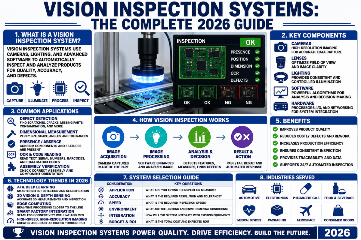
What Is a Vision Inspection System? (And How It Actually Works)
Vision inspection system A vision inspection system acts like the inspectors’ eyeballs (an industrial camera, really) and his brain(the software logic), replacing it’s subjectivity. Machines do not only ‘see’ better – they eliminate the human elements of fatigue, shift drift, and changeover drift from decision making, meaning why a machine can complete a 100% inspection while sampling every hour. Authorities respect that difference: US FDA claims humanvisualdetection of a particulate is a probabilistic outcome dictated by defect size and contrast , the precise problem that automatic inspection exists to solve.
Under the hood, almost every machine vision system operates with the exact same (four-step) sequence to accomplish its mission in milliseconds:
- Acquisition. As the workpiece arrives at the camera’s view, a trigger (encoder pulse, photoelectric sensor, timer) triggers the camera. Exposure, aperture, lighting geometry, and trigger timing are determined here-if they’re incorrect nothing downstream can recover.
- Then software then extracts the edges, areas, textures and locations pertinent to the application (feature extraction)-high contrasts patterns in the case of the barcode; borders in the case of the linear measurement; areas out of whack for defect finding.
- Region-of-interest masks confine computation to the areas of interest (detection and segmentation) thereby reducing compute and removing false positives from background noise.
- D) finally, software identifies the part, checks conformance or measures to a CAD tolerance, and responds with a digital I/O accept/reject, a record of inspection results, or a position correction signal to a robot or PLC (decision+output).
It’s that final step, though, that makes a vision inspection system truly “automated” – making a picture into the pass/fail signal the machine or line can act upon. Standards that link these vision components to communication infrastructure (GigE Vision and USB3 Vision as well as plant-level protocols PROFINET, EtherNet/IP etc.) carry out the command and the information beyond the vision system to the MES, SCADA, and PLC system level of the plant.
How do machine vision systems detect defects?
They look for deviations from a definition of what’s good. A rule-based system inspects image properties, such as the contrast of edges, blob areas, distances, colors, etc. If these properties don’t fall within a range, it flags them as bad. The deep-learning system learns the appearance of good parts (and possibly bad parts if examples are labeled) by processing images from a training set and rates how close a new image is to one of the good samples. In either case, lighting has to make the defect visible in the first place. Even though a scratch is only half a pixel, a darkness condition (dark-field illumination) may light up the scratch against a dark background, because the technique relies on contrast, not on resolving the whole shape of the imperfection. In both approaches, consistency is a huge improvement over humans and advanced AI-powered systems may extend the reach of defect detection to features that human inspection rules cannot describe and to parts that may have formerly escaped detection. Therefore, a reliable automated vision system hinges on the right balance of light, optics, sensor, and software – the weakest link in the chain sets the limit.
Four Building Blocks: Camera, Lighting, Lens, and Software
While people often fixate on the camera, a machine vision inspection system is actually a combination of four different components, where the camera is not typically the limiting factor. “The sensor is the heart of the system,” claims A3, the Association for Advancing Automation, yet most failure-inducing events trace back to lighting or optical issues rather than megapixels. Every link impacts image quality, and a given set of machine vision hardware (camera, lens, lighting) is limited to the strength of its least robust component. This is why a humble smart camera sensor, combined with appropriate illumination, may perform better than a costly camera alone. Let’s examine each link and the most common failures encountered.
| Component | What it does | Key spec to get right | What fails if wrong |
|---|---|---|---|
| Lighting | Creates contrast between defect and background | Geometry: dark-field, backlight, coaxial, dome | Real defects vanish; no algorithm recovers them |
| Lens / optics | Frames and focuses the image, sets field of view | Telecentric vs standard; distortion, depth of field | Edge measurements drift; parallax errors on height |
| Camera / sensor | Captures the image (area-scan or line-scan) | Resolution, frame rate, global vs rolling shutter | Motion blur; a round hole images as an ellipse |
| Processing software | Applies inspection logic, makes the decision | Rule-based vs deep-learning; ease of use | False rejects or escaped defects; brittle to change |
Component model corroborated by A3/automate.org and machine-vision basics references.
📐 Engineering Note — the resolution math (a first-order estimate, not a guarantee)
As a back-of-the-envelope estimate of the smallest feature a machine vision system can discern, one can calculate the smallest detectable defect based on: size of defect Field Of View / Sensor Pixels / Pixels Per Defect. For example, assume the widely accepted notion that a defect must span a minimum of three to five pixels to be confidently detected and classified. If we’re using a 5 MP sensor with a pixel array size of 2448 pixels across and have a 60-mm field of view, the smallest detectable feature size is 60 / 2448 / 3 = 0.073 mm. With a 12 MP sensor with a pixel array of 4096 pixels and the same field of view, we can achieve an estimate of 60 / 4096 / 3 = 0.044 mm, or if we narrow the field of view to 30 mm, the 5 MP sensor can deliver a maximum resolution estimate of 30 / 2448 / 3 = 0.037 mm. Remember, these numbers provide a rough baseline, and the true resolving power depends on the modulation transfer function (MTF) of the camera and lens combination, measured under typical operating conditions rather than by megapixel specifications. Remember also, a larger megapixel number will result in reduced frame rate and signal level for each pixel.
What are the components of a vision inspection system?
Four principal elements – light, optics, the sensor/camera and the computer program – are acquired, analyzed, and exploited as one unit. A common specification has now emerged for camera quality independently of the supplier, with the International standard (ISO 12232-1:2024, ISO 24942) for a standardized procedure for measurement of camera characteristics (quantum efficiency, readout noise, dynamic range, etc.) based on methods defined by the EMVA 1288.
Types of Vision Inspection Systems: 1D, 2D, 3D, and Smart Camera vs PC-Based
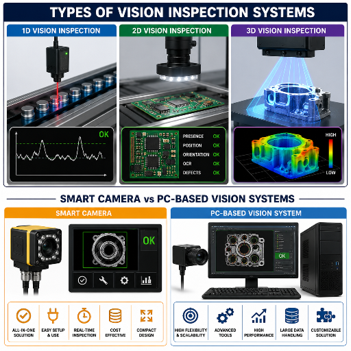
There are two ways to divide vision inspection systems: by how they image (1D, 2D, 3D) and by where processing occurs (architecture). Buy the wrong system by mixing them up. Shop for the imaging first, then the architecture.
The 2D-or-3D Decision Line
There’s one decision rule that outranks the others on picking an imaging solution. Apply 2D when the problem is within the plane of the image – scuffs, missing-component detection, print inspection,barcode reading, inplane dimensions. It’s faster and cheaper, and still the dominant installed system.
Turn to 3D, however, the instant that the defect is a “Z” variable: height, depth, volume, coplanarity, even warpage. Think of a lifted component lead, a plastic molded without fully filling the die, a dented container, or bin picking that requires the object be known in all six directions of motion. 3D vision requires gathering an extra depth map or point cloud-through some variant of 3D scanning such as laser triangulation, structured light, stereo or time of flight at a higher price tag and system cost-to know these additional data points; but it’s growing the fastest just as robots and shrinking tolerances force work into a region outside of what can be seen in just two dimensions. Line scan cameras span the other axis: they construct a high-resolution image of web stock (films, foils, paper or electrodes) that travels at speed-the entire width is never in view for a two-dimensional camera; you build an image 100% across a strip moving at hundreds of meters per minute using a line camera system.
| Architecture | Where processing lives | Strengths | Best-fit work |
|---|---|---|---|
| Smart camera | Self-contained in the camera housing | Simple to deploy, low cost, compact, rugged | Single, well-defined check in a stable environment |
| Embedded / vision sensor | Compact controller or GPU board (Jetson/FPGA) | Balances performance and footprint | Moderate complexity, machine-builder integration |
| PC-based | Industrial PC running many cameras | Greatest flexibility and compute; multi-camera | Complex multi-task lines; sub-micron metrology |
A1 series architecture divided according to A3/automate.org “Smart Cameras vs. PC-Based Machine Vision Systems.”
Here is the raw truth on this architecture decision – PC-based gives you the largest flexibility range and that comes at a cost for footprint, system integration and dollar cost.Most lines do not need this. A smart camera that inspects brilliantly a single aspect of the process is better than a PC-based system that has too many options and not enough care and support.
What Vision Systems Inspect: Defect Classes and Detection Methods
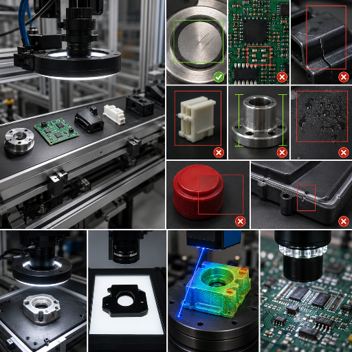
Buy a solution that reduces complaints (stops sending defects)-not a list of defects. The vision system is responsible for the entire continuum of optical-defect types, and the method determines the reasonable minimum size for each – not the camera. The following figure breaks out the typical class with its typical inspection method and minimum size:
| Defect / inspection class | Imaging / method | Typical minimum detectable |
|---|---|---|
| Surface scratch / crack / burr | Dark-field (low-angle) lighting | Sub-pixel by contrast; ~0.05–0.1 mm typical |
| Dimensional / tolerance (metrology) | Telecentric lens + backlight | few-µm accuracy; sub-µm on 3D profilers |
| Presence / absence of feature | Backlight silhouette or area-scan | Feature-scale (hole, pin, clip, seal) |
| Code & character (barcode, OCR/OCV) | High-res area-scan + diffuse light | Character / cell scale; ~99.99% read accuracy |
| Color / shade verification | Color camera + dome light | Shade-class |
| Assembly / positioning | Coaxial + area-scan, or 3D | Component-scale; sub-mm placement to ~0.1 mm |
| Foreign material / contamination | Dark-field + AI classification | ~0.1 mm and up |
| Solder / weld joint quality | Multi-angle or 3D profiling | Joint-scale; IPC-A-610 Class 3 criteria |
| Edge defect (chip / notch / split) | Backlight + sub-pixel edge tools | ~0.05 mm |
The measurement figures are Moore-like (e.g., the Keyence IM-8000 has top figures of 3.9 m accuracy and 0.5 m repeatability in controlled conditions, etc). Citation needed for the OCR/OCV reads.
Color inspection (a color camera and a dome light) and 3D inspection (a 3D camera) expand the list of defects to shade matching and height defects, which are critical for finished product quality assurance throughout the supply chain. Yet there are two objective limitations to the list. Parts with chamfers, radii or mirror finish are genuinely more challenging because the top light will reflect from their curved surfaces, and that’s a lighting problem, not a resolution problem. There is another common mistake: Some might confuses OCR (optical character recognition – which reads a text to trigger an action) with OCV (optical character verification which checks if the text is a specific one). In regulatory tracing applications, requirements for DataMatrix 2D codes are precise: DSCSA regulates pharmaceutical packs by the FDA, while the EU Falsified Medicines Directive (Regulation 2016/161) ensures the Data Matrix provides at least print-quality grade 1.5 under the ISO/IEC 15415 standard.
Can 3D and line-scan detect cylinder surface defects?
This applies to cylindrical inspection; indeed, we need to combine multiple methods in such case to detect all flaws on the inspection part. By syncing line scanning camera to the rotary part, we’re creating a straight surface view of a curved surface so that scratches can’t be missed while we change the frame of inspection. A 3D inspection can add to this the element of height difference between the part surface and the printed inspection mark which cannot be identified using standard camera inspections as flat 2D surface cannot distinguish that information. Combined use of line scan image, together with a 3D surface profile of the inspection part makes for effective identification of round objects, defects like dents, burrs on surfaces or overall geometry anomalies that can be missed by the standard cameras. As discussed previously, the trick still consists on getting the lighting on surface correct – it’s not about how small you can see but how to see.
Automated Optical Inspection (AOI): The PCB and Electronics Special Case
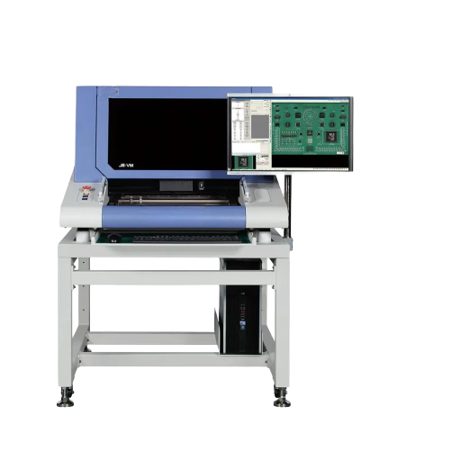
Automated optical inspection (AOI) is the term the electronics industry employs for vision inspection of printed circuit boards.AOI stands for Automated Optical Inspection which in the PCB industryis widely used inspectionprocess. It is an industry unto itself for the type of tiny, dense, standardized defects detected-such as solder bridges, tombstones, missing components or lifted leads-which correspond to accepted IPC-A-610 classes. As a segment the AOI market is worth hundreds of millions of dollars annually – 2024 market estimates for this inspection category generally hover around $850 million (depending on analyst firms) – and AOI is one of the fastest-growing inspection technologies in response to increasingly smaller component pitch dimensions down to 0.3mm for 0201 parts and the requirement for zero-defects for automotive and medical electronic devices.
One significant source of confusion for AOI buyers is cost; an “AOI system” can mean anything from a budget price point to many multiples higher. The AOI Cost Ladder shown here outlines AOI price tiers along the AOI line, highlighting the corresponding types of defects addressed at each stage.
| Tier | Where it sits | What it catches | Relative cost |
|---|---|---|---|
| Desktop / offline AOI | Bench, batch sampling | Presence/absence, gross placement, basic solder | Entry |
| Inline 2D AOI | In the SMT line, 100% boards | Component, polarity, 0.4 mm-pitch solder, OCR | Mid |
| Inline 3D AOI | In the SMT line, height-aware | Solder volume, coplanarity, lifted leads, tombstones | High |
Tiers are dynamic, with exact costs for your inspection system dependent on your board dimensions, cycle time requirements and integration details.
The number all AOI buyers underestimate is integration. The cost of integration, calibration and operator training represents anywhere from 10-25% on top of the cameras’ retail price – for a multi-station production line, engineers can cost more than all the cameras. Consider your system investment, not just your cameras investment.
Rule-Based vs Deep-Learning (AI) Vision: When Each Wins
Machine vision has its own ‘rule-based versus AI’ fallacy. There are simply distinct tasks – and the answer usually isn’t either/or. Classical (rule-based) computer vision measures defined elements, providing the fast, precise, explainable solution needed for gauging or clearly defined, repeatable tests. Deep learning has a real sweet spot in highly variable or fuzzy surfaces an algorithm would struggle to address. Deep learning, however, can be split. Supervised approaches that recognize specific defects require hundreds to thousands of labeled images per defect category. unsupervised methods train on only good examples and identify aberrations – the far better option if defects are few, unpredictable, or have not yet been observed.
✔ Rule-based vision wins when…
- This inspection is based on dimensional gauging, and requires a clear pass/fail threshold.
- You need speed, determinism, and an explainable result
- Defect-free reference parts are few and consistent
- An auditor requires clarification of the exact reason for the rejection of a specific part.
⚠ Deep-learning vision wins when…
- Surfaces vary (organic, textured, cosmetic) and rules get brittle
- A sufficiently large volume of images is available (or alternatively, solely “good” samples will be provided, in the case of anomaly detection) to train a model.
- The defect set is fuzzy or evolving
- However, beware: The performance on a benchmark cannot be reliably transferred to a live production environment when lighting or product variations fluctuate.
This final caution is the detail often disregarded by vendors. A model exhibiting strong performance on a controlled benchmark can exhibit significantly lower performance in a production setting if the lighting, fixturing, or product diversity deviates from what was used during the training phase-a well-documented failure mechanism in industrial inspection. Larger models do not automatically resolve this issue; a thoroughly controlled and validated image acquisition setup is essential. The patent activity from 2024-2025 confirms this direction: new patents, such as US10964004B2, disclose deep learning AOI methodologies that improve the rate of filtering out false defects, while systems such as WO2021225876A1 formalize the use of deep learning for automated visual inspection. Published evidence of improvements is substantial where the imaging conditions are rigorously controlled (defect detection yield increased from 66% to 95% in one case study), but these gains are only realized within such a context. ZEUEE’s hybrid approach judiciously utilizes rule-based solutions for efficiency where they are applicable, and employs deep learning classifiers solely in those instances where variabilities dictate their use.
How to Choose a Vision Inspection System: A 7-Question Screen

The vast majority of failed machine vision projects stems from a failure to adequately define the problem. To make sure you are asking the right questions before approaching any vendors, answer this free 7-question assessment. Your answers will translate directly into critical design decisions concerning cameras, illumination, architecture, and software.
| # | Question | What the answer decides |
|---|---|---|
| 1 | Which defects must you catch (the actual list)? | Lighting geometry + method per defect |
| 2 | What is the smallest defect size? | Resolution, field of view, optics |
| 3 | How many parts per minute? | Camera frame rate, shutter, architecture |
| 4 | Is the defect in-plane (2D) or a height/volume (3D)? | 2D vs 3D imaging (the Decision Line above) |
| 5 | Is the defect well-defined or variable? | Rule-based, deep-learning, or hybrid |
| 6 | How does it integrate (PLC, MES, accept/reject)? | I/O, protocols, handling, data logging |
| 7 | Build, buy off-the-shelf, or custom-engineer? | Vendor type (see the landscape below) |
Answering all seven questions will provide the basis for an effective Request for Quotation (RFQ). You can also check the appropriate resolution-to-defect-size calculator based on your answers to Question 2. If you uncover evidence that the part is complex, requires multiple inspections, or warrants a fully integrated inspection cell instead of a single camera, consult a system builder rather than a catalog provider – which is precisely the approach ZEUEE takes when developing our vision inspection systems.
Cost and Vendor Landscape: Cognex, Keyence, Integrators, and Custom OEMs
Vision-system pricing is opaque on purpose – premium brands rarely publish list prices – but the cost is driven by a handful of factors you can self-estimate: the number of defect types and inspection stations, the required accuracy, the throughput, whether the algorithm is rule-based or deep-learning, and the integration scope. Identical-looking vision inspection machines can quote 2-3x apart depending on which kind of vendor you buy from. Vision providers package optical inspection systems and broader inspection solutions across the full range of inspection systems, so two products marketed as “vision solutions” can differ sharply in capability and price.
| Vendor type | Examples / model | Best for |
|---|---|---|
| Smart-camera brands | Cognex, Keyence vision systems | Standard checks, fast deployment, strong support |
| System integrators | Local/regional integrators | Multi-vendor retrofits, combining existing gear |
| AI-vision platforms | Deep-learning software vendors | Variable surfaces, anomaly detection, labeling tools |
| Custom OEM builders | Non-standard machine builders | Bespoke inspection cells engineered to your part |
Is Cognex or Keyence better?
There is no universal winner, and any guide that crowns one is selling something. Practitioners on the r/PLC community put it plainly: both do largely the same things, and “you need adequate system lighting and ambient lighting” regardless of brand-fit and lighting beat badge. As a working rule of thumb from the field, Keyence tends to win on ease of use and turnkey deployment, while Cognex is favored for full-fledged deep-learning applications and the most demanding jobs. Which way to go depends on your defect list, your team’s vision experience, and your integration scope – exactly the seven questions above.
💡 Pro Tip
Ask every vendor to prove detection on your parts before you sign. Entry-tier ROI can be fast-in one widely-cited Control Engineering case, a USD 9,500 Teledyne DALSA system at Polaris Industries cut scrap by 23% and paid back in about two working weeks – but most integrated deployments land in an 18-36 month payback window. Low sticker price rarely means the lowest total cost.
Deployment Reality: Why Vision Projects Stall (and How to De-Risk Yours)
Here is the uncomfortable truth about vision inspection: the hard part is not buying the system – it is making it work on a real line and keeping it working. Projects stall in deployment far more often than they fail at the demo, and the cause is almost always a mismatch between the system and the actual part, lighting, and product variation rather than a weak camera. A3 frames it directly: vision inspection systems are complicated and must be implemented correctly to realize the long-term benefits. Here is a de-risking sequence that survives contact with production:
Vision deployment de-risk sequence
- Build a real defect library first. Collect imaged examples of the actual defects (and good parts) you must catch – deep-learning needs them, and rule-based thresholds are set from them.
- Validate lighting on real parts, not renderings. Lock the lighting geometry to your part before choosing the camera; a 0.1mm defect that images cleanly under dark field can vanish under bright field, so benchmark accuracy does not transfer if the illumination is wrong.
- Prove detectability before sign-off. Run a factory acceptance test (FAT) and an on-site acceptance test (SAT) on your real parts – the documented release gate ISO 9001:2015 Clause 8.6 expects.
- Don’t qualify the demo, qualify the measurement! The Gage R&R attribute / measurement-systems-analysis study (reference the AIAG MSA manual) will verify that the system agrees with the standard and with itself, whether operated by operators, teams, shifts, etc. (most programs consider greater than 90% attribute agreement acceptable.) – specify the effectiveness metric you are accepting, rather than a round percentage.
- Don’t be fooled by a larger compliance envelope. For regulated industries, the only output of meeting USP, the “GO,” or an ISO certification, is to obtain a required permit or register a new machine. Even then, any machine guarding mechanism, robot, or machine press that is incorporated into the machine vision system will necessitate guarding per OSHA 29 CFR 1910.212.
We size the lighting and optics to the customer’s worst defect, prove the detectability on their real parts, and only then gets the customer’s sign-off. A spec sheet that provides only one accuracy number and doesn’t give you a false reject number is half telling a story so that we provide the number for both and tuned it to the line’s quality level.”
— ZEUEE Engineering Team, Machine Vision & Non-Standard Automation
And again, where ZEUEE experience demonstrates in build, not the pamphlet-our 150-plus patents across nine industrial sectors for vision cells, that stage the lighting before the camera and confirm detection in your product-the example being that in production, one of our CCD pin-diameter measurement systems can find .1mm detection in as few as 25 parts per minute. And that discipline extend into upstream assembly and downstream test equipment should your project also incorporate connector inspection automation and automated testing systems.
Where Vision Inspection Is Headed: AI, 3D, and Edge (2026)
For machine vision inspection, the shift in the center of gravity away from hard-coded, hand-written rule systems towards machine-learning algorithms-not just headline market sizes-is the most important driver for a today-purchase. Three trends explain the migration. The first trend is the increasing adoption of deep learning; it’s tackling applications where rule-based vision historically performed poorly: cosmetic, organic and naturally varying surfaces ( evidenced by the growing patent filings).
The second trend involves the rapidly accelerating growth rate for 3D machine vision, outpacing the broader market; its rise is fueled by the use of robotics, bin-picking applications, and demand for assessing height, flatness, or warped parts. The third trend is the move toward edge AI, specifically withinsmart cameras and embedded controllers; this decentralizes the AI decisions, performing inference inside the camera, rather than in a central server.
The practical takeaway for a customer is more specific: “Order with systems that can integrate deeper learning classifiers at a later date, and make sure cameras or controllers have headroom for AI on the edge so they won’t be orphaned come time to make the purchase in 2026 after my defect set grows and changes.” Increasingly tight rules for zero defects and traceability – such as from FDA (DSCSA), the EU (FMD), and tighter automotive quality standards – compel the entire market segment toward in-line 100 percent verification (regardless of which AI algorithm becomes standard). In fact, even as vision technology moves toward the edge, in-line, high-assurance, high-throughput inspections utilizing intelligent machine vision are now the cornerstone of nearly every quality organization. (For those in business – machine vision solutions are in the low tens of billions; this will probably expand to around the mid tens of billions with 8% to 10% yearly growth; that’s how you know the importance not an ordering guide!)
Frequently Asked Questions
What are vision inspection systems?
View Answer
Machine Vision Systems are camera-based, automated inspection instruments that check production items for errors, sizes, coding and accuracy of structure without human oversight. A system consists of 4 pieces- illumination, lens, machine and processor to capture an impression of a subject, analyze this against an interpretation of “correct, and pass/fail or estimate in 10ms using same criteria across entire batch for consistent results.
What are the 4 types of inspection?
View Answer
In the manufacturing sector there are four basic methods to check any part as it progresses thru production: incoming, intra-process, finished article, and pre-delivery check. On the other hand, if discussing machine vision specifically, work is categorised as finding defects or anomalies, making size comparisons, determining the availability or absence of items, and read barcodes or letters. Quite often a vision system completes numerous at a time.
Is Cognex or Keyence better?
View Answer
No model has proved any more successful than the other – both solve alternative requirements. Both Cognex & Keyence will complete same essential inspection types successfully and those who have experience with machine vision typically emphasize that placing correct light on your product and suitability for task are significantly more vital than model title. However typically, Keyence gets triumph on speed and uncomplicated application, whereas Cognex’s strengths include comprehensivedeep-learning applicationsand those require-ments most critical inspection operations. Pair the model with your exact failure and processing rates as well as your business group’s practical experience utilizing machine vision.
How much does an AOI system cost?
View Answer
Automated optical inspections may run to a full order of magnitude in price: desktop systems used for taking a sample are the least costly; SMT systems that do inspections on 100% of the boards and inline 2D inspections represent moderate level; inspection that measures volume of the solder & surface levels for coplanarity (in 3D) belong to a premier group. Whether your camera expenses will be low or higher, estimate an integration of installation, alignment and training of around 10-25% above – for example a high tech installation involving more than one phase and you should be prepared to pay much higher for the installation than the camera itself. Calculate costs based on the actual, physical item inspected.
What industries use vision inspection systems?
View Answer
By industry, heaviest users involve such as vehicles, electronics as well as semiconductors, pharmaceutical along with healthcare medical devices, beverages and food and also manufactured sheet materials such as film, paper, & electrode of batter. All rely upon these kinds ofautomated inspection solutionsto guarantee no item errors as well as ensure regul-atory complianceand visibility of process flow, which is extremely challenging with manual approaches.
Why use a vision inspection system instead of manual QC?
View Answer
The reasoning is as follows-human inspectors are prone to drifting standards (e.g. with fatigue), however a vision machine maintains an absolutely consist-ent assessment criterion at speed and provides fully auto-mated logging. This is, therefore, suitable for 100% inspection (rather than sampling).
How do vision systems support traceability and QA?
View Answer
Each inspection results in a detailed log entry such as defect type, location of defect, measurement, barcode value, and timestamp. This information goes directly into the shop floor system for quality tracking. This provides auditable traceability, fulfilling such regul-atory needs like pharmaceuticals product serialization DSCSA. It likewise supplies crucial inputs designed for improving the manufacturing process over the long term.
About This Analysis
These unbiased guidelines utilized machine vision industry benchmarks (ISO 12233:2024, EMVA 1288, IPC-A-610),FDA and USP inspection guides, AIAG’s MSA, A3 references, and ZEUEE’s non-standard vision cells used in various businesses (such as electronics, autos, medicine, as well as renewable power). The direct measurements regarding vision performance and lighting sequences come from ZEUEE-manufactured devices. The article was evaluated by theZEUEE expert technical team.
References & Sources
- ISO 12233:2024 — Photography, electronic still-picture imaging, resolution and SFR — International Organization for Standardization
- Visual Inspection of Injectable Products for Visible Particulates — U.S. Food and Drug Administration
- Drug Supply Chain Security Act (DSCSA) serialization — U.S. Food and Drug Administration
- Toward Standardization and Consistency of Visible Particle Testing — NIST
- Commission Delegated Regulation (EU) 2016/161 (Falsified Medicines Directive) — EUR-Lex
- Automate 2025: Machine vision standards update (EMVA 1288 → ISO 24942) — Control Engineering
- Smart Cameras vs. PC-Based Machine Vision Systems — A3 / Association for Advancing Automation
- US10964004B2 — Automated optical inspection method using deep learning — USPTO / Google Patents