Get in touch with Zeyu lntelligent Industrial Company

Connector Contact Types Explained: How Twist-Pin, Hyperboloid, and Stamped Contacts Compare

Connector contact types are the manufacturing method and socket geometry inside a connector – twist-pin, hyperboloid, or stamped-and-formed – and this choice, not the outer shell, is what governs mating-cycle life and shock resistance.
Quick Specs
| Manufacturing method | Machined (turned) or stamped-and-formed |
| Socket geometry (machined) | Twist-pin, hyperboloid, or solid/turned |
| Governing standard | MIL-DTL-39029 (contact), MIL-DTL-38999 (circular shell), MIL-DTL-32139 (twist-pin), MIL-DTL-83513 (Micro-D) |
| Typical mating cycles | 750-5,000 (stamped/standard D-sub) up to 100,000+ (hyperboloid) |
| Shock rating (hyperboloid) | 250 g / 0.4 ms per IEC 60068-2-27 |
| Contact pitch range | 1.27 mm, 2.00 mm, 2.54 mm (common) plus miniature sub-mm variants |
| Contact size / wire size | Size #16-#22 typical, matched to 28-16 AWG wire size depending on current |
| Voltage and current class | Signal-level (low voltage/low current) through several hundred volts and tens of amps, contact-size dependent |
It’s this contact-level choice, not the outer shell style, that decides if the connector makes it through 500 mating cycles or 100,000, and if it’s resistant to shock loading or subject to periodic failures in the field. The engineer choosing a connector will typically start with the shell style-round, D-sub, rectangular-then find out that, much later, the contact on the inside is the real key to reliability. This white paper examines the three contact families of most importance to electromechanical and defense-adjacent applications.
There are two distinct types of connector contact based on machining process (machined and stamped-and-formed), and for the machined type based on the socket geometry (twist-pin, hyperboloid or solid/turned pin). Twist-pin contacts will offer more than 7 micro-contact points on a male pin versus 2-3 on a stamped one. And for the hyperboloid contacts it goes further with an rating in excess of 100 000 mating cycles, with a 250 g shock load rating based on IEC 60068-2-27, which stamped and solid/turned contacts cannot match.
In This Guide
- Two axis taxonomy – manufacturing method vs. socket geometry is a separate decision
- Twist-pin’s advantage over stamped connectors under vibration, due to 7 points of contact.
- Hyperboloid’s assured 250 g / 100,000-cycle rating and the quiet revolution in value of its stamped model.
- A 4-standard cross-walk (MIL-DTL-38999 / 39029 / 32139 / 83513) nobody else published in a table
- A plating choice with more depth than the “gold is gold is gold” choice.
Connector Contact Types at a Glance
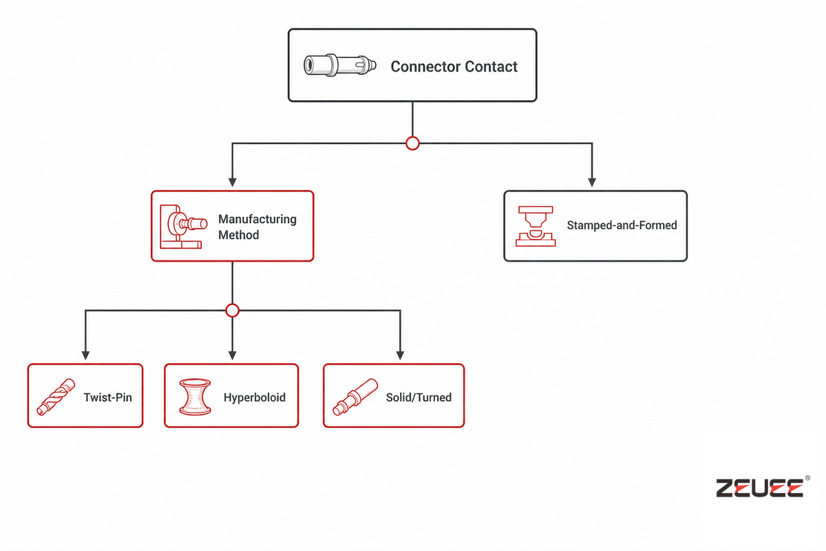
Each electrical connector is defined by two independent design factors operating in parallel: the number of contacts the individual connector carries (i.e. the number of wires used to carry the current and form the contact surfaces), and the socket geometry of each individual contact. Standard buying guides talk of a continuum of contact type, from cheap to expensive, whereas in practice, there are two stacked design choices. Choice number one: what manufacturing method do you want to use?
Do you machine the contact from bar stock, or do you stamp and form the contact from sheet metal?
The connector contact types chart below (an electrical connector contact types comparison) lays out all three families side by side. Connector and interconnect reliability under harsh conditions is an active university research area, precisely because this taxonomy decision has downstream reliability consequences. The same reasoning applies to any heavy-duty connector family carrying signal and power together, not just the three contact types covered here, and it holds whether the connector bodies in question use contact arrangements of two pins or two hundred. If you choose stamped, there’s no socket-geometry choice – the contact is a single stamped and formed piece of material, end of story. If you chose machined, there are then three choices of socket geometry – do you use a twisted wire bundle (twist-pin), a wire basket with hyperbolically shaped strands (hyperboloid), or a simple bore which you’ve turned or drilled?
| Contact Type / Attribute | Twist-Pin | Hyperboloid | Stamped-and-Formed |
|---|---|---|---|
| Manufacturing method | Machined / wire-wrapped | Machined (turned) or stamped variant (HCS) | Stamped and formed sheet metal |
| Micro-contact points | 7 or more | Multiple wire lines, full 360° wrap | 2-3 |
| Typical mating cycles | Several thousand (family-dependent) | 100,000+ | 750-5,000 (sub-D/M-type family) |
| Shock rating | High (MIL-spec qualified) | 250 g / 0.4 ms (IEC 60068-2-27) | Lower; datasheet-dependent |
| Insertion force | Moderate (wires compress into socket) | Very low (VLIF), under 1 oz for size #22 | Low to moderate |
| Relative cost | High | Highest (turned) / moderate (HCS stamped variant) | Lowest |
| Governing standard | MIL-DTL-32139 | No single dedicated MIL spec; qualified under connector-family specs | MIL-DTL-39029 dash numbers |
| Automated crimp/insert compatible | Yes | Yes (HCS variant purpose-built for reel-fed crimping) | Yes, high-volume default |
| Best-fit application | MIL-spec Micro-D, harsh-vibration signal paths | Aerospace/defense, medical sterilization cycles, high-cycle test equipment | Cost-sensitive, high-volume commercial builds |
💡 Pro Tip
Don’t start with “machined or stamped?” Start with: how many mating cycles and how much shock will this contact see in service? The answer usually picks the manufacturing method for you.
Manufacturing Method: Machined vs. Stamped-and-Formed Contacts
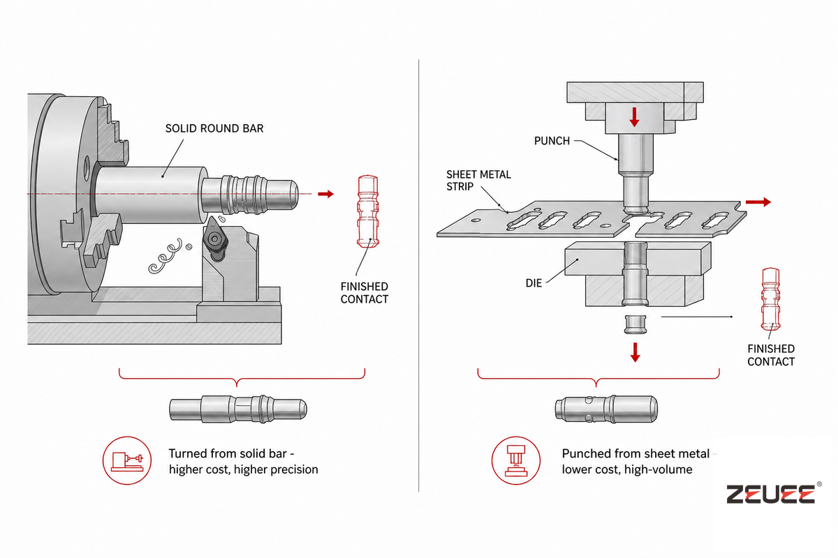
You’ll see in just about any industry buyer’s guide for connectors that “machined contacts offer higher power density, lower resistance, and higher current compared to stamped contacts and have better strength and durability”-no numbers attached to these statements, however. Those are the numbers in which connector selection mistakes lurk. Here’s what’s really going on: A stamped-and-formed contact is simply a piece of sheet metal that’s punched and formed-optimized for cost and ease of feed by automated crimping machines. A machined contact is turned from a solid bar of material-or in the newest hybrid cases, stamped and rolled into a geometry that approximates a turned one-optimized for number of contacts, type of wipe action, and duty cycle. Environmental operating temperature range-which often has absolutely nothing to do with the shell geometry contact type but a lot to do with which plating and insulating materials material will withstand that range without degrading-is another easy-to-miss but important factor: the general purpose circular connector can operate from -40°C to +85°C, while its sealed, harsh environment version goes from -55°C to +125°C. Mating/unmating forces likewise grow with the number of contacts; a tiny D-sub style connector might specify maximum mating force of 3.3 N per contact and minimum unmating force of 0.25 N per contact, which is easily manageable for a dozen positions but can become an ergonomic problem with several dozen, driving designers to zero-insertion-force (ZIF) connections in the highest pin-count scenarios. Sealed versions of these most product lines provide IP67 or IP68 ingress ratings to protect against dust and water ingress, respectively. Push-pull connector families are a good example of how contact choice and mechanical design work together: their machined contacts are a large part of why they’re rated for 5,000-plus mating cycles, well above a typical stamped-contact connector. None of this is specific to male pins versus female connectors either – the same contact-family logic applies on both halves of a mated pair, since making a reliable electrical connection depends on the contact geometry, not which side carries the pin.
Factors to Weigh: Machined vs. Stamped
- * The expected mating cycles for the life of the product. Stamped/standard D-sub contacts are rated to approximately 750 cycles at lower pin densities and based on plating, but high-end push-pull and hyperboloid machine contact designs are rated well over 5,000 and 100,000 cycles, respectively.
- * Exposure to vibration and shock. Machined twist pin and hyperboloid contacts retain contact even during motion, helping to minimize temporary signal drops.
- * Cost, volume and termination type. The stamped/formed approach is a natural fit for high-volume commercial builds where per-unit termination cost is paramount and designed to feed easily into automated crimping machinery, regardless of which termination type is ultimately selected.
- * Contact resistance and current carrying capabilities. While any connection’s ability to handle high current/low resistance will increase as you decrease contact count and increase contact area, the inherent design of machine contact geometry keeps this property more consistent across the life of the connector.
Another quiet and very costly mistake: We often treat the decision as a one-time cost choice rather than considering the total cost of ownership over the lifetime of the device. A connector contact failure most often traces back to physical damage, contamination, or an installation error rather than a single catastrophic event. The connection between mechanical integrity and electrical performance under the actual conditions of operation for the device is critical, and an undersized contact is often a choice that looks fine on the bench but results in a failure months or years into field service. Sandia National Laboratories’ connector reliability research and other industry failure analysis reports consistently point to these as the primary causes; factor in the enormous gap in rated mating cycles (hundreds of thousands for hyperboloid compared to several thousand for standard stamped contacts) and it becomes clear the failure often starts with an inadequate selection for the device’s intended operating conditions rather than an inadequate selection for the shell itself.
“Connectors that pass incoming inspection still fail in the field more often from a mismatched duty-cycle rating than from a bad part. The contact family has to match the actual mating-cycle and vibration profile, not just the connector’s headline spec sheet.”
— Common field observation among connector reliability engineers
Twist-Pin Contacts: Construction, MIL-DTL-32139, and the 7-Point Advantage
What is a twist-pin contact?
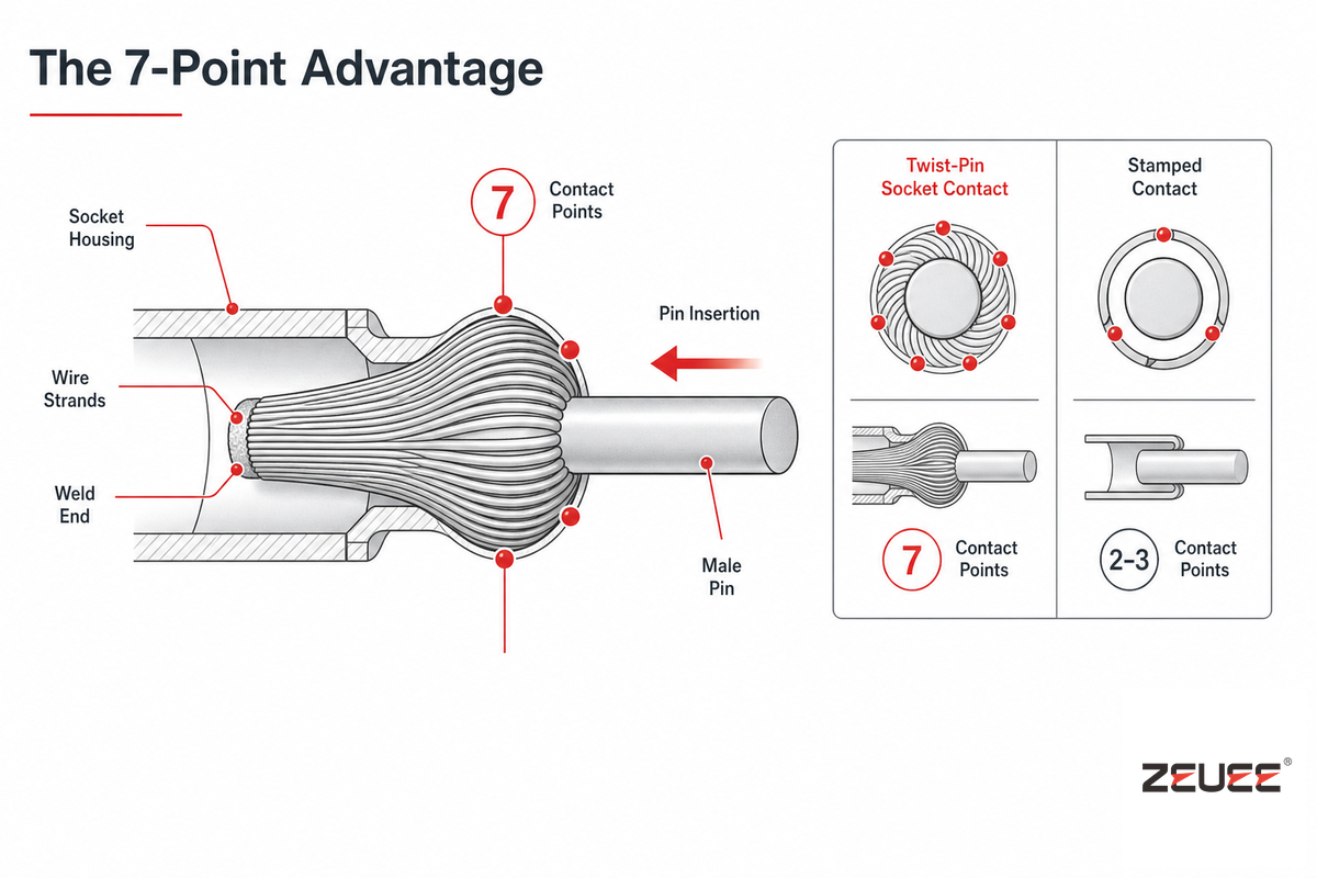
The twist-pin is a machined socket contact made of a bunch of beryllium copper wires welded at one end, rounded, and expanded outward like a mushroom to provide a spring action. Most twist-pin parts ship as a removable crimp contact rather than a fixed one, so a damaged contact pin can be extracted and replaced without scrapping the whole connector.
As a male pin is slid into a twist-pin socket, the mushroom bundle of wires is squeezed around the pin and each of the wires functions as an individual point contact rather than as a machined surface. The only reason that the twist-pin performs better than its stamped counterpart in an environmental situation, is because of this: the redundancy of contacts lets the connection survive even if any one point loses contact through wear, contamination, or momentary separation during a shock event.
The improvement isn’t merely a marketing concept, it’s a documented, two source statistic. A stamped contact has only 2-3 points of contact, whereas a twist-pin contact has 7 or more independent points of contact, as independently noted in two separate sources for Micro-D connector performance. That’s a 2.5-3.5x jump in redundant contact paths for one mated pair, enough of an edge to keep a signal alive through a shock that would momentarily open the single contact surface on a stamped design.
📍 Engineering Note
The spring-loaded, multi-point contact-pressure principle behind twist-pin construction has a long patented lineage (see, for example, US Patent 5,897,404 for a socket terminal using a separate spring member to increase contact pressure). Twist-pin contacts are qualified under MIL-DTL-32139, which specifically defines twist-pin plug contacts, as separate from the general purpose contact family which are covered by MIL-DTL-39029. If the bill of materials mentions a Micro-D or circular connector contact without specifying one or the other, it’s worth pursuing further to understand which standard is governing the part as it carries different mechanical and dimensional requirements.
Hyperboloid Contacts: The Wire-Basket Design Built for 100,000+ Mating Cycles
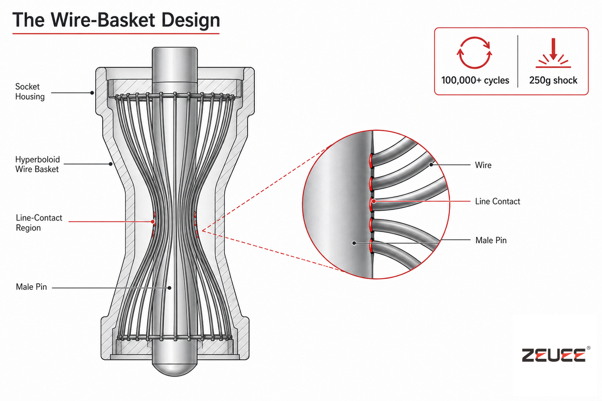
A hyperboloid contact uses a hyperbolic-shape surface, instead of a cylindrical surface, for electrical contacts. The hyperboloid surface consists of multiple wires in the shape of hyperbolic curves. As a pin enters the connector, the wires elastically bend to follow the contour of the pin, thus creating multiple line-contact regions. This creates the performance enhancements claimed below: it spreads out the electrical current and mechanical forces across multiple contacts rather than a single surface or wire bundle.
100,000+
Mating Cycles
250 g
Shock, 0.4 ms (IEC 60068-2-27)
<1 oz
Insertion Force, size #22
Smiths Interconnect’s Hypertac-brand hyperboloid contacts are documented sustaining 100,000 insertion/extraction cycles with no measured performance degradation. The same source reports its own shock testing, using the IEC 60068-2-27 shock test method, at 250 g over a 0.4 ms half-sine pulse, along with sine-vibration testing per IEC 60068-2-6 at 20 g from 10 to 2,000 Hz and random-vibration testing per IEC 60068-2-35 at 0.5 g²/Hz across the same frequency band-the IEC standards define the test methods, while the specific pass/fail ratings are the manufacturer’s own qualification results, not figures published by IEC itself. The smallest practical hyperboloid pin diameter is around 0.3 mm, with effectively no upper limit on the larger end. NASA’s own analytic modeling of first contact resistance gives a sense of just how much basic physics research underlies why multi-point contact geometries behave the way they do. IEH Corporation, a second, independent connector manufacturer, confirms the same order-of-magnitude cycle life, stating that its hyperboloid contacts exceed 100,000 mating cycles against a 10,000-to-20,000-cycle range for many standard connector contacts-a five-to-ten-fold difference. That cycle-life gap is precisely why hyperboloid contacts show up disproportionately in aerospace, defense, and medical-device connectors that are mated and demated dozens of times during sterilization, diagnostics, or maintenance cycles rather than once at final assembly.
Here’s the finding that should reshape how buyers think about the machined-versus-stamped question: hyperboloid geometry is no longer exclusive to machined, turned contacts. Contact manufacturers now offer a stamped-and-rolled hyperboloid variant-built to the same wire-basket principle and mechanically compatible with turned hyperboloid contacts-specifically to cut cost and enable full automatic crimping-machine processing. That directly contradicts the common assumption that “hyperboloid” and “machined-only, high-cost” are the same thing. The real decision driver is socket geometry (does the design need multi-wire wrap contact?), not manufacturing method (machined versus stamped)-the two are separable, and a buyer who rules out hyperboloid performance purely because “we need a stamped, high-volume solution” may be working from an outdated assumption.
Standards Crosswalk: The Circular Connector’s MIL-DTL-38999, MIL-DTL-39029, and MIL-DTL-32139
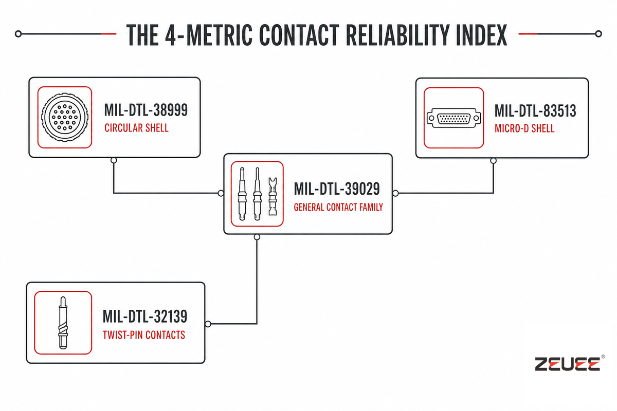
A circular connector isn’t governed by one MIL specification-it’s governed by a stack of them, each covering a different physical layer, and no single competitor resource currently maps all four in one place. MIL-DTL-38999 covers the circular connector shell itself: currently at Revision M with Amendment 2 (dated 2017), confirmed active by the Defense Logistics Agency’s official specification index (ZEUEE covers the assembly-equipment side of this standard in its own MIL-DTL-38999 machine guide). Contacts that go inside that shell-and inside several other connector families-are covered separately by MIL-DTL-39029, a general contact specification broken into individual dash-numbered sheets (for example, one MIL-C-39029 sheet explicitly covers crimp-removable pin contacts for use in MIL-C-24308 and MIL-C-38999 Series I through IV connectors). Twist-pin contacts specifically fall under their own dedicated specification, MIL-DTL-32139, separate from the general MIL-DTL-39029 family. Micro-D connectors-the miniature cousin of the 38999 family-are covered by yet another standard, MIL-DTL-83513, with contacts still drawn from the MIL-DTL-39029 dash-number system (see our Micro-D connector guide for the full MIL-DTL-83513 shell-size breakdown). Parts-screening and acceptance documents such as NASA’s EEE-INST-002 instructions illustrate just how granular this dash-number-level bookkeeping gets in practice. It’s also worth remembering these four standards don’t cover every one of the many types of circular electrical connectors on the market – smaller metric families like M5 connectors and M8/M12 industrial-automation connectors are simply different types of circular connectors that follow entirely separate specifications with their own dash-number systems. Mixing these up on a purchase order is a real, recurring headache: a buyer who orders “MIL-DTL-38999 contacts” without a specific MIL-DTL-39029 dash number, or who assumes a Micro-D contact and a standard circular-connector contact share a part number, routinely ends up with parts that fit the wrong shell or miss the wrong crimp tooling entirely.
| Standard | Governs | Current Status |
|---|---|---|
| MIL-DTL-38999 | Circular connector shell (bayonet/threaded/breech coupling, environment-resistant) | Rev M + Amendment 2 (2017), Active per DLA |
| MIL-DTL-39029 | General pin/socket contact family, dash-numbered per connector-family fit | Active, multiple dash sheets |
| MIL-DTL-32139 | Twist-pin plug contacts specifically | Active |
| MIL-DTL-83513 | Micro-D connector shell (miniature, high-density) | Active |
Contact Plating and Materials: Gold vs. Silver vs. Rhodium
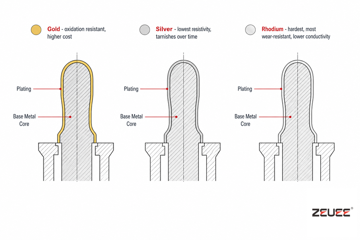
It’s in choice of plating where the ‘expensive is best’ aphorism starts to fall apart most conspicuously. Gold is the obvious choice for signal level connector contacts due to it’s resistance to oxidation, and it also helps keep contact resistance consistent over time. Plating always sits on top of a base contact material – typically a copper alloy chosen for its own mechanical strength and conductivity – so the plating decision and the underlying contact material decision are two separate specifications, not one. However, several independent industry sources, some referring to MIL-STD-1353 (which discusses gold and nickel plating), recognize that it’s comparatively expensive, and may not be the most cost-effective option depending on the actual operating environment, current requirements, and expected life cycle count of an application.
As a pure element, silver has less electrical resistivity than gold; this has been known for a very long time, and NIST’s own historical resistivity survey of 16 pure metals tabulates the data to support it. The catch is that silver forms an oxide/sulfide film that has considerably more resistance than gold does under normal conditions; the potential advantages of silver can be quickly eroded in any environment outside of laboratory conditions if proper controls aren’t put into place around the mated connection and interface.
Plating Decision Guide
- In a corrosive or humid environment, gold-plates the contact of low current signals, although for higher cost, because an oxidization resistant gold layer ensures the stability of the signal over the desired life span.
- Silver plating can also be used on high-current power contacts where immediate conductivity is a greater concern than susceptibility to oxidation with time, assuming the connector will be isolated from atmospheric effects.
- In high wear, high micro-motion, and fretting corrosion sensitive applications, at least one hyperboloid contact manufacturer’s internal design handbook suggests against use of oxidizing coatings such as gold to avoid increase of fretting related contact resistance, and instead proposes the use of lubrication and contact force.
- Where extreme wear resistance and hardness are the priority, rhodium plating gets selected in spite of its higher cost and lower conductivity relative to gold or silver.
A common, avoidable mistake at the specification stage is to gold plate a whole family of connector without seeing how it affects the cost per part at the production volume – this will go unnoticed on a single sample part but becomes a material line item once it’s rolled up into the entire production run. On the topic of just how much contact resistance a given plating provides you, a data point example from a single DOE-funded reliability study on photovoltaics connectors (of 75 connectors from three manufacturers) found the average contact resistance to be on the order of 2.3 milliohms per connector. Note that this number is for the particular sample of PV-connectors used in that single study and not a universal value across contact types and plating types, so it’s best to view this number only as a rough order of magnitude guide line and verify the actual resistance value for any given contact, plating, and pitch against the part datasheet itself.
Pin-and-Socket Assembly: Termination, Insertion, and Automation
Before any contact even makes it into the connector housing, it needs to be terminated to a wire and inserted into place – and each of these steps has its own set of reliability concerns. There are three terminations in common use today: crimp, where a tool cold-weld (or crimps) the contact barrel over the stripped wire (no solder involved), solder, where a solder is pressed directly to a pin or cup on the contact, and insulation displacement connectors (IDC), where a cutting blade slits through insulation as the wire is pushed in, removing the need for a pre-stripping step altogether. Crimp termination is prevalent on high-volume, field-serviceable designs from roughly 28AWG up to 10AWG wire sizes because it’s fast, reliable and compatible with automated feed machinery. a solder contact is frequently found on PCB mount and Micro-D style parts, and IDC termination is almost exclusively used on ribbon cables and telecommunications-style connectors where stripping each conductor individually would be unwieldy. Crimp connectors dominate by sheer volume across all three contact families discussed in this guide, simply because crimping scales to automated production better than either alternative. No matter which termination is selected, the crimp contact or solder joint is only one half of the equation – the strain relief work-hardens and breaks the conductor at the junction of cable and connector housing is frequently the actual failure mechanism.
📍 Engineering Note
The widely adopted general rule of thumb for successful pin-and-socket engagement calls for a minimum contact engagement length of at least 1.5 times the pin diameter.
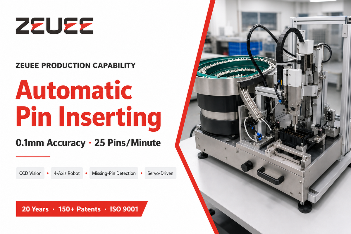
A common connector-selection guide categorizes the contact-counts into three useful levels: low-contact (2-4 position) for low-power or simple-sensor circuitry; medium-contact (5-12 position) for power-plus-data industrial automation; and high-contact (13+ position) for multi-channel data-acquisition and communications systems – and a given voltage covers roughly 24 V to several thousand volts over that same range of connector families. Once the contacts are terminated, putting the pins or sockets into the connector housings at scale is a precision-tolerance issue, not merely a labor one. For example, ZEUEE’s Automatic Pin Inserting machine achieves 25 pins/minute with a positioning accuracy of 0.1 mm using a combination of CCD vision, a four-axis robot, servo-driven insertion, and in-line missing-pin detection on a 3500 W platform. This 0.1 mm positioning band falls comfortably within the robot repeatability range for industrial robots, as set forth by ISO 9283 for the purpose of robot testing – the standard a potential buyer can use to vet the accuracy claims of an automated pin-insertion system against something other than the vendor’s marketing brochure. With large pin-counts, manual insertion also presents a problem of operator strain, not just one of throughput – the insertion-force values that are so important for zero-insertion-force connectors are just as applicable for a human operator trying to seat a pins or sockets as for a connector mechanism. For manufacturers that are still inserting contacts manually in large numbers, speed coupled with sub-0.1 mm positioning is the tipping point at which an automated line’s throughput and first-pass yield become superior to the labor costs of manual insertion – especially when you include missing-pin detection, since a single undetected missing contact reaching final assembly costs much more to rework than the added cost of automating the insertion process. This holds whether the line is running a standard catalog part or a custom connector configuration built to a customer’s own drawing. This same reliability logic underpins published research on estimating remaining useful life for power connectors: catching a defect at assembly is always cheaper than catching it after deployment.
How to Choose the Right Contact Type for Your Application
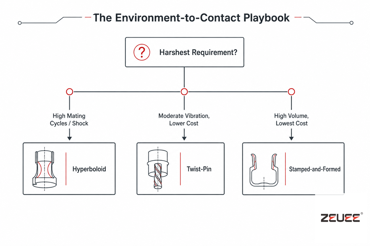
Selecting a connector contact is ultimately a matter of matching capability to duty cycle, and the Environment-to-Contact Playbook below integrates the preceding six sections into a single selection pass. Standard machined and stamped connectors are available off-the-shelf across all three families discussed here; some connectors are designed around one specific contact geometry from the start and can’t be retrofitted with another, while other modular connectors allow a degree of contact-family substitution within the same shell. No connector solutions provider gets every one of these trade-offs right for every application, and how much current a given connector can handle depends far more on contact size than on which of the three families is chosen. Begin by identifying the harshest single requirement that you face – number of mating cycles, exposure to shock/vibration, or unit cost – since this should be the deciding factor, not a vague sense of “how rugged does it need to be.” (Sandia’s and Auburn’s connector-reliability research both point the same direction: match the contact family to the actual duty cycle first, then work the cost down from there.)
✓ Choose Hyperboloid When
- mating cycles, more than 10-20K.
- Shock/vibration exposure is severe (aerospace, defense, field test equipment)
- Low insertion force required (high pin-count connectors, periodic field servicing)
- Machine-grade cost is supported by the budget, or an HCS stamped variety would work
⚠ Choose Twist-Pin or Stamped Instead When
- Twist pin (e.g., MIL-DTL-32139-qualified Micro-D) and/or the ability to withstand a moderate amount of vibration at a lower cost than a hyperboloid type
- Stamped and formed, cost is the most significant factor and total usage volume is large, while the expected mating cycles value is only a few thousands.
- The mated automatic pin-insertion machine must work at high speed, with a minimum per-unit cost.
Industry Outlook: From Category Terms to Specific Contact Technologies
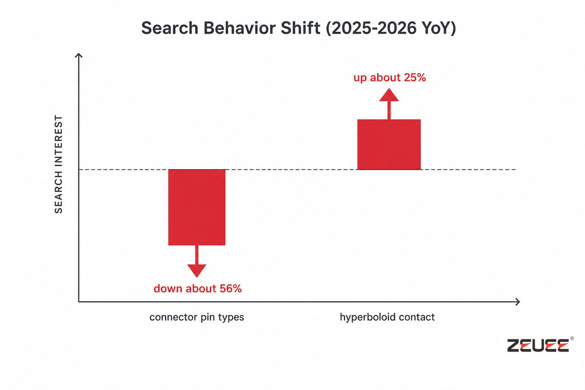
But a clearer indicator of where connector-contact buying behavior is heading is the search activity around it. Verified platform search volume data shows that broad category term “connector pin types” declined about 56% YoY while the specific technical term “hyperboloid contact” is up about 25% YoY over the same timeframe (2025-2026). Taken together, this isn’t noise – buyers are abandoning the broad category search and are instead honing in on the contact technology that they’ve identified as necessary. What this means practically for anyone who needs to specify or document connector contacts for 2026 program cycles is to quit writing and searching for generic category terms like “connector types” and “contact types” and instead, ground all documentation, RFQs, and parts selection on the specific technology name and applicable governing specification – i.e., twist-pin per MIL-DTL-32139, hyperboloid per the applicable connector-family specification, or stamped-and-formed per MIL-DTL-39029 – because that’s where both the searches and, more and more, the sourcing discussions are taking place. A buyer who keeps searching and specifying only by broad category term risks landing on generic connector-shell content that never even mentions twist-pin, hyperboloid, or MIL-DTL-32139 by name-exactly the gap this guide fills. Government-funded contact-reliability research, like NASA’s decades-long work on contact heat transfer, shows this is a deep, ongoing field, not a settled one – connector systems that once shipped as one-size-fits-all are increasingly spec’d contact-by-contact instead.
As context only: Bishop & Associates’ 2025 industry review forecast low double-digit growth for the connector market in 2025, in the range of 12-15%. That number is purely directional market context, not the driver of the recommendation above; the shift in technology-specific search and sourcing patterns is the real driver.
Frequently Asked Questions
Q: What are the two types of connector contacts?
View Answer
At the highest level, connector contacts are categorized as either machined or stamped-and-formed. Machined contacts are turned from barstock, with some new hybrid designs stamping a geometry resembling turned contacts, and include twist-pin and hyperboloid socket types; they command a premium in price but offer longer mating-cycle life, better vibration resistance, and lower long-term contact resistance. Stamped-and-formed contacts are stamped and formed from flat sheet metal, directly feed into Automated crimping systems, and are a good fit for cost-sensitive, high-volume designs in which a moderate number of mating cycles (in the low thousands) is anticipated.
Q: What are the three types of connectors?
View Answer
By convention, connectors are described according to their application level: Board-to-board connectors connect printed circuit boards directly (no cabling is involved). Cable-to-cable connectors connect the ends of two cables to extend a circuit path or enable field service. Cable-to-board connectors connect the end of a cable assembly to a circuit board. This guide goes one level deeper than these application types, addressing the choice of contact technology that fits within any of these connector types. Whether connecting to a board, cable, or other cable, twist-pin, hyperboloid, or stamped contacts can be used.
Q: What is a cylindrical connector?
View Answer
A circular (cylindrical) connector is a round connector (typically of circular connector shell construction using bayonet, threaded, or breech lock mating) used in harsh environments where resistance to vibration, corrosion, shock, and dust is required. The connector’s circular shell construction (common among the aerospace, defense, and industrial applications) is separate from the choice of contact technology; for example, the circular connector shells are often designated per MIL-DTL-38999, whereas the pin and socket contacts that reside within the shell might be per MIL-DTL-39029 and, in the case of twist-pin technology, MIL-DTL-32139.
Q: Why use ruggedized connectors?
View Answer
Ruggedized connectors are certified to withstand severe environmental conditions, including high/low temperature, vibration, shock, dust, moisture ingress that would normally cause a standard commercial connector to fail well before the end of its normal service life.
Q: Does a connector need EMI/RFI protection?
View Answer
only when the application involves sensitive signal lines adjacent to strong electromagnetics. The cost of adding shielded shell and filtered contacts to an application that only requires a power connector isn’t justifiable.
Q: What are the 7 different types of cable connectors?
View Answer
Industry references commonly organize cable connectors into seven families by application: audio/video connectors, automotive connectors, circular connectors, connector accessories, contacts (the subject of this guide), D-shaped connectors, and fiber optic connectors.
These families delineate their particular shell shape and usage context, however the contact technology – twist-pin/hyperboloid vs stamped-and-formed – might occur across more than one family rather than being unique to any particular family. An ability to make consistent decisions regarding reliability based on this distinction at the connector-contact level regardless of which connector family you may be interested in can often be very important.
We manufacture twist-pin, hyperboloid, and high-volume stamped contact assemblies at scale.
Why We Write This
ZEUEE designs and manufactures automated pin-insertion and connector assembly equipment for twist-pin, hyperboloid, and terminal-style contact families, which is why this guide focuses on contact-level performance rather than shell shape alone. The 0.1 mm accuracy and 25 pins/minute figures are first-party results from ZEUEE’s own Automatic Pin Inserting platform. Reviewed by the Shenzhen Zeyu Intelligent Industrial Science Technology Co., Ltd technical team.
References & Sources
- MIL-C-39029/58E Military Specification Sheet — EverySpec.com (U.S. defense specification archive)
- MIL-DTL-38999 Specification Index — Defense Logistics Agency
- MIL-DTL-38999 Revision M, Amendment 2 — EverySpec.com
- Reliability Model Development for Photovoltaic Connector Lifetime Prediction — U.S. Department of Energy, Office of Scientific and Technical Information
- Survey of Electrical Resistivity Measurements on 16 Pure Metals — National Institute of Standards and Technology (NBS Technical Note 365)
- PV Connectors Reliability Research — Sandia National Laboratories
- Connectors and System-Level Interconnects: Degradation and Wear — Auburn University CAVE Research Center
- US Patent 5,897,404 — Socket Terminal — USPTO / Google Patents
- An Analytic Model for Estimating the First Contact Resistance — NASA Technical Reports Server
- Heat Transfer Between Surfaces in Contact — NASA Technical Reports Server
- EEE-INST-002: Instructions for EEE Parts Selection, Screening, and Qualification — NASA (hosted via MIT)
- On-Line Remaining Useful Life Estimation of Power Connectors — National Institutes of Health, PubMed Central
Related Articles
- Connector Assembly Machines — automated equipment for pin/socket contact insertion, crimping, and testing
- Connector Assembly Machines: A Complete Guide — selecting and automating connector assembly production lines
- DC Connector and Adapter Cable Line Guide — contact and termination choices for DC power connectors
WHY WE WRITE THIS
About ZEUEE Engineering Insights
ZEUEE shares technical guides based on real automation project experience. Since 2005, we have designed and manufactured non-standard automation equipment for connector assembly, wire harness production, robotic lines, vision inspection, and smart factory upgrades.
Founded in 2005
20,000 m² production base
120+ specialists
150+ R&D patents
ISO9001:2015 certified