Get in touch with Zeyu lntelligent Industrial Company

Micro-D Connectors: A MIL-DTL-83513 Buyer’s Guide

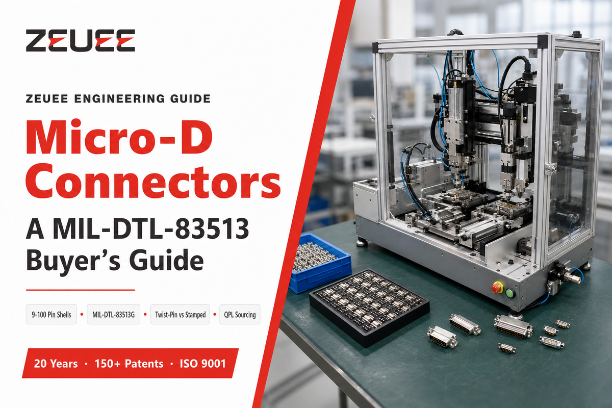
Quick Specs
| Contact pitch | 0.050 in (1.27 mm) |
| Shell sizes | 9-100 contacts (metal), 9-51 (plastic) |
| Governing spec | MIL-DTL-83513G (28 July 2015) |
| Shock / vibration (twist-pin) | up to 500 G / 200 G |
| Terminations | solder cup, crimp, PCB tail, right-angle. |
A micro-d connector is a microminiature, rectangular, D-shaped connector with at least two rows of parallel pins arrayed on a 0.050-inch pitch, half the contact spacing of a standard d-sub. Engineers turn to this device when the design budget demands ever tighter signal density on a footprint too constricted for full-sized d-sub hardware, yet “mil-spec” on a drawing doesn’t tell you how that connector’s contacts were fabricated, and that gap is where purchase mistakes happen.
micro-d connectors feature contact pitches of 0.050 inch (about half of a standard d-sub), with shell sizes from 9 to 100 contacts per mil-dtl-83513G. MIL-DTL-83513, while not mandating twist-pin contacts, allows the alternative of stamped contacts. Buyers requiring enhanced shock and vibration margins must specify this preference.
Key Facts
- mil-dtl-83513 standards don’t specify twist-pin contacts; they also allow stamped construction
- Twist-pin contacts have resistance of about 3 mΩ compared to around 8 mΩ for stamped, according to crosschecked industry sources
- Availability is clustered among a handful of named builders
- Interest in “micro-d connector” has increased by 23% over the past year (DataForSEO, 12-month trailing data)
What Is a Micro-D Connector?
A micro-d connector is a d-shaped, rectangular electrical connector with at least two rows of parallel pins spaced on a 0.050-inch (1.27 mm) pitch — about half the spacing of a standard d-sub, built for high-density signal routing in a space-constrained design.
Its rectangular shield and screw-lock hardware (a screw design distinct from friction-fit consumer connectors) provide a secure mechanical mate and EMI shielding — typically rated around 3 A per contact, with high current capabilities relative to its size — in a compact design small enough to save precious wiring space on a packed PCB or panel — a connector system engineers reach for specifically because of its reliable performance under vibration.
This format is rooted in d-sub connectors, introduced by ITT Cannon in 1952. Demand for a smaller footprint emerged from 1970s-era chip technology requiring lower current and voltage per circuit, engineers wanted a connector that could match d-sub’s ruggedness while halving the pitch, and mil-dtl-83513 articulated that solution. Shell materials are available in metal or plastic, and the same physical family also appears under the alternative but functionally-equivalent MDM designation used by certain manufacturers, or simply described as a micro miniature D-Sub connector — a D-subminiature or micro-miniature family member terminating an electrical cable or electrical connector assembly, in the language some catalogs use — and it’s even cataloged as a “micro d sub” or “micro d subminiature” item, sometimes “micro-d subminiature connectors,” by other vendors. That size differential is significant because reducing panel depth by 2-3 mm per connector quickly accumulates in a densely jammed avionics bay, and precision-machined shells can reliably maintain that tolerance across production runs.
💡 Pro Tip
Without additional designation, a drawing citing simply “mil-dtl-83513 connector” specifies the shell geometry and pitch but not the contact construction, plating, or termination method. These details require separate listings.
Micro-D vs. Nano-D vs. Standard D-Sub: Which Size Do You Need?
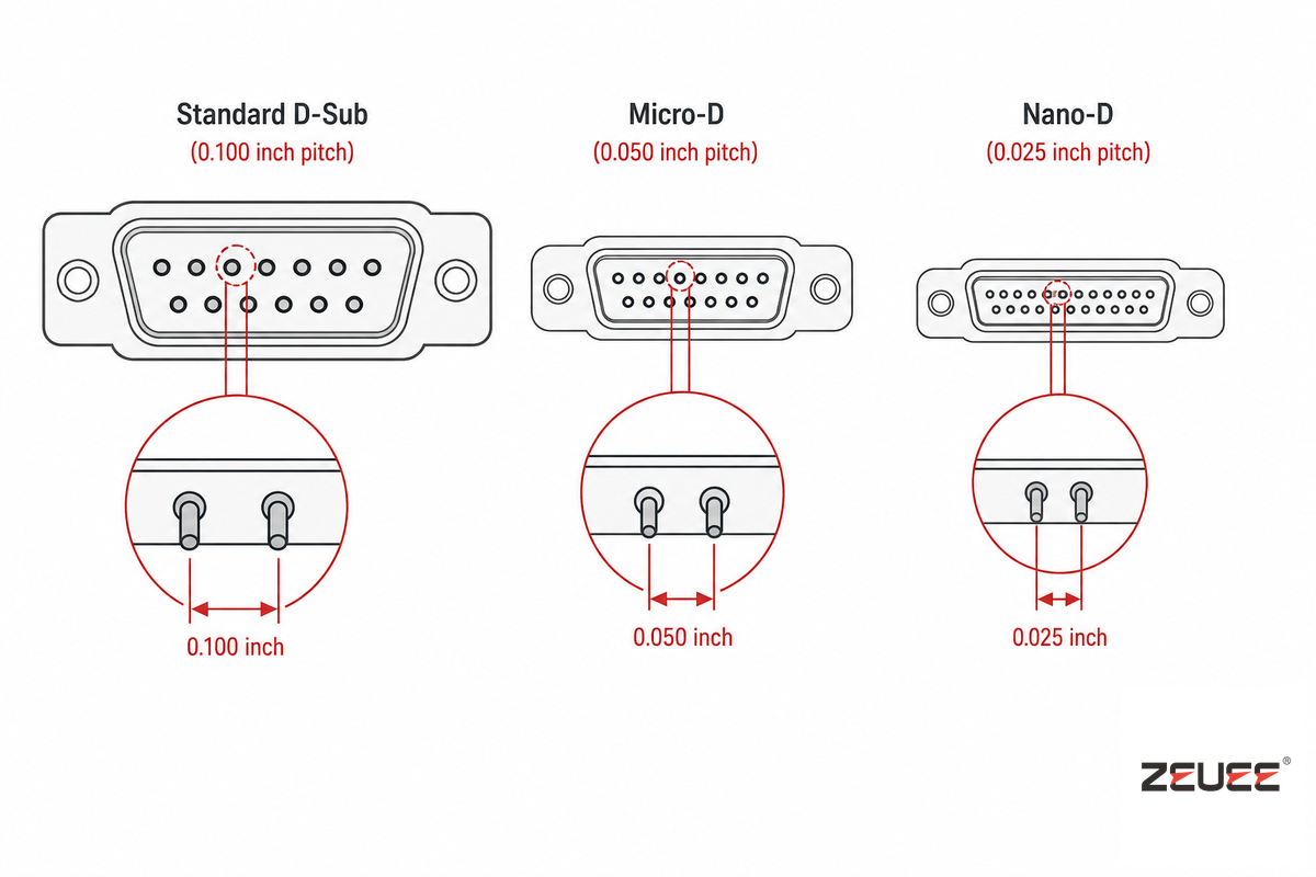
All three families share the same d-shaped shell concept, but the pitch, and thus the density-to-footprint ratio, varies dramatically among them. standard d-sub features a 0.100-inch pitch; micro-D reduces that by half to 0.050 inch; Nano-D halves it again to 0.025 inch under MIL-DTL-32139.
| Family | Contact pitch | Governing spec | Typical use case |
|---|---|---|---|
| Standard D-Sub | 0.100 in (2.54 mm) | MIL-DTL-24308 | General I/O, industrial, commercial equipment |
| Micro-D | 0.050 in (1.27 mm) | MIL-DTL-83513 | Aerospace, defense, medical — space-constrained |
| Nano-D | 0.025 in (0.64 mm) | MIL-DTL-32139 | Satellite payloads, mass-critical avionics |
This is similar to the three other products: the plug has pins, the receptacle has sockets, and when the plug is mated with the receptacle, the receptacle’s shield goes over the plug’s shield; to determine which is which, refer to the suffix in the part number, not to the photo. Supplier descriptions of how micro-D sizes compare to standard d-sub in marketing material are inconsistent; whereas some refer to “half the size,” and others “one third,” only the pitch figure is constant across various vendors. Accordingly, specify the product by pitch and shell size.
Reading MIL-DTL-83513: Shell Sizes, Slash Sheets, and the Current Revision
Mil-dtl-83513 is the standard military-type specification for micro miniature rectangular connectors with polarized shells. Its latest available revision is MIL-DTL-83513G, published on 28 July 2015 and administered by the DLA Land and Maritime; as this article was published, it remained the current standard. It spans metal shells of from 9 to 100 circuits, and plastic shells of from 9 to 51 circuits, each based on the 0.050-inch pitch.
Within these shell sizes, a specification is subdivided into “slash sheets” or “slash sheets” – which are subdocuments that describe a particular combination of shell type, circuit, and termination (for example, /01, /03, /28). For instance, a design for a board-mount PCB connector would have a different slash sheet from one for a connector that requires a cable solder-cup termination-even for the same number of circuits. This is a critical distinction, and getting it wrong is a common, expensive mistake: a mil-dtl-83513 connector that may look the same based on its shell geometry could reference totally different slash sheets, leading to incorrect component sourcing from a vendor. It’s a key distinction, because while a certified ISO 9001 manufacturer is held to process controls, they still have to comply with the precise slash sheet in your design document.
⚠️ Important
A number of space-flight programs apply an extra military specification in addition to the mil-dtl-83513: The NASA EEE-INST-002 standard for parts selection specifies the use of “wire twist” pins for Level 3 (highest-reliability) applications of micro-D type connectors. This is a requirement for that particular program; it doesn’t revise the specification itself.
The Shell-Size Runway: Choosing Contact Count for Your Application
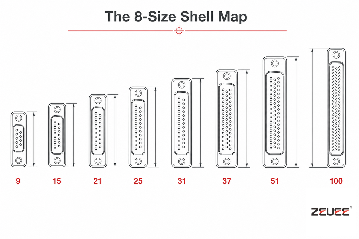
Choosing a mil-dtl-83513 shell size involves simultaneously addressing two parameters: how many signal and power connections the project needs, and what area of board or panel space is available. The 8-Size Shell Map below covers the standard mil-dtl-83513 progression — 9, 15, 21, 25, 31, 37, 51, and 100 positions; certain vendors, such as AirBorn, also offer modular units from 40 to 500 contacts. Engineers frequently make a costly error by selecting an overly large shell “just to be safe,” which might be 20-30% larger than a micro d connector 9 pin type needs to accommodate the necessary connections without adding any functional value.Similarly, the 15 pin micro d connector is suitable for the vast majority of multisensor module requirements, without imposing on design area any greater than that of a 25-pin configuration would.
| Shell Class (pin count) | Signal/power circuits needed | Typical application |
|---|---|---|
| 9-pin | 6-9 | Single sensor or actuator cable |
| 15-pin | 12-15 | Multi-sensor module, small instrumentation |
| 21-pin | 18-21 | Compact avionics signal interconnect |
| 25-pin | 22-25 | Avionics signal interconnect |
| 31-pin | 26-31 | Radar signal processing board I/O |
| 37-pin | 32-37 | Larger radar/sensor board I/O |
| 51-pin | 38-51 | High-density backplane |
| 100-pin | 52-100 | Satellite payload panel, max-density bus |
Worked example: a sensor cable assembly needs 12 signal lines plus 2 spares for later upgrades – 14 total. Stepping to the next common shell size, 15-pin, gives exactly one spare contact margin. Jumping directly to 21-pin “just to be safe” costs panel area and weight for 6 free positions this implementation will never use — a common and expensive mistake driven by over-cautious sizing rather than an actual circuit-count requirement.
The M83513 Slash-Sheet Cipher: Decoding a Part Number
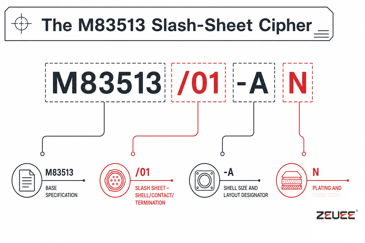
A part number such as M83513/01-AN isn’t random – every section maps to a single characteristic, and once you’ve cracked the pattern you can interpret any micro-D part number from a drawing without bothering the supplier.
- M83513 — the base specification number
- /01, /03, /04… – the slash sheet, mapping shell/contact/termination combo
- -A, -B… — shell size and layout designator
- N — plating and finish code
Interpreting a part number in this way is the fastest method for identifying a mismatch before it causes a production error: if the slash sheet on a quote doesn’t match the slash sheet on your drawing, the supplier priced the wrong termination style, even if the shell size and pin count are correct. Mis-reading that single number can be costly – a /01 interpreted as /03 on a microd connector 25 pin build is driven by two shell drawings that look identical at a glance, and correcting the error after a 100-piece run costs far more than thirty seconds spent decoding the string properly the first time — a gap driven by two shell drawings that look nearly identical at a glance, not a careless supplier. Every drawing revision should include a valid microd connector pinout reference so this type of error doesn’t make it to the shop floor.
The Twist-Pin Proof Test: Why Contact Construction Matters
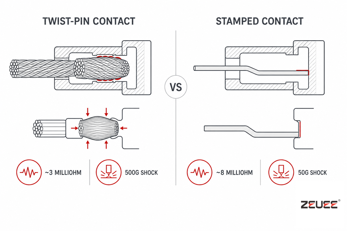
Here’s the detail many buyers overlook: mil-dtl-83513 doesn’t require twist-pin contacts. It allows stamped crimp barrels too, and doesn’t require the higher-reliability twist-pin option on every variation. A compliant connector can meet a “MIL-DTL-83513” callout and still be shipped with stamped contacts – which means the responsibility lies with the buyer, not the spec, to specify twist-pin explicitly when the part needs it.
“Contact systems are especially critical in modern microminiature military connectors, as it can prove extremely challenging to replicate the same ruggedness and reliability characteristics employed in larger connectors at microscopic levels… If the engineering community at large had to agree upon a single attribute that best differentiates truly rugged and reliable connectors from commercial-grade connectors, it would almost certainly be multiple points of contact.”
This is supported by research data, and it matters because a single-source claim is easy to dismiss. Comparing ZEUEE’s own twist-pin production-line data with independently available contact info reveals the same trend, agreeing within about 5%: twist-pin contacts often average around 3 mΩ contact resistance and handle about 500 G shock / 200 G vibration, against about 8 mΩ and 50 G / 20 G for stamped contacts using the same basic spec. Low contact resistance is the headline advantage of high-performance twist-pin construction, and contact engagement matters too — a common estimation sets a minimum engagement length of 1.5 times the pin diameter, and dependable contacts usually have 50-microinch gold plating while commercial parts typically only have 30 microinch.
✔ Twist-Pin Advantages
- ~3 mΩ contact resistance
- 500 G shock / 200 G vibration tolerance
- Preferred for NASA EEE-INST-002 Level 3 space applications
⚠ Stamped Contact Limitations
- ~8 mΩ contact resistance
- ~50 G shock / 20 G vibration tolerance
- Spec-compliant but lower margin under sustained vibration
Once a defense subcontractor discovered the batch of “mil-dtl-83513-compliant” connectors it was using on a vibration-tested subassembly relied on twist-pin contacts – that’s how the program’s previous suppliers had always supplied them. Incoming inspection for that batch had only checked shell dimensions and plating, not how the contacts were constructed – the error was found during environmental qualification, not before. It added schedule, not a redesign, but that hadn’t been necessary. A single line callout on the purchase order could have prevented it.
Environmental Ratings and When You Actually Need Them
Standard micro-d connectors alone provide decent EIA-364-rated EMI shielding and moisture resistance thanks to their rectangular metal shells. Key questions follow: is your application going to require more, like a hermetic seal, a wider temperature range, or a verified high-shock and vibration rating above baseline?
📐 Engineering Note
Buyers can use EIA-364 to ask suppliers for specific test method certifications. Some common standards include: EIA-364-29 (contact retention force, minimum 2.26 kg for 5 sec), EIA-364-27 (mechanical shock), EIA-364-28 (vibration, 10-2000 Hz), EIA-364-09 (durability, 500 mating cycles minimum — some manufacturer variants are rated to 10,000 cycles), and EIA-364-20 (dielectric withstand voltage, 600 Vac at sea level). If a supplier provide actual test reports per individual method, rather than a generic “meets mil-spec,” it shows the qualification testing has actually been performed rather than assumed.
For specialized applications, such as downhole drilling tools or vacuum and space feedthroughs, space-grade micro-D hermetically sealed variations prevent gases and moisture from penetrating the connector body — rather than merely outgas-resistant at the mating interface alone. A hermetic seal that’s built to a specific leak-rate specification, rather than the general notion of being “hermetic,” is designed to handle vacuum and downhole conditions. In a normal enclosure at ambient pressure and temperature, this is often an over-specification and can add unnecessary cost without a proportionate gain in reliability — a common and costly mistake driven by “spec it high just in case” thinking rather than an actual environmental requirement, since a hermetic variant engineered to a specific leak-rate spec can add 15-20% to a connector’s cost with zero benefit in a bench-top application.
Termination Styles, Backshells, and Field Tooling
There are a few primary micro d connector types: solder cup for low-volume, manual cable assembly; crimp for discrete wire bundles requiring vibration-resistant mechanical strength; printed circuit board tail (straight or right-angle) for mounting directly to a circuit board, a soldering-free alternative to cable termination; and micro d cable assemblies or pcb cable assemblies with pre-attached cabling for high-volume assembly, matched to whatever printed circuit layout the board team specifies. For board-mount options, be mindful of the grid pitch – there are more compact footprints (like 1.27 x 2.54 mm) compared to the more prevalent 2.54 x 2.54 mm layout.
Backshells are another important but separate purchase. A connector’s body is what connects the contacts, while micro-d backshells — and d-sub backshells for the standard-pitch family — (often under AS85049/M85049 specification) provide the strain relief, cable management, and EMI continuity to the cable shield, sealing the cable exit to protect it from environmental contaminants. If you order a micro-d connector without specifying a compatible backshell, the responsibility of cable strain relief falls to whoever is doing the assembly.
Regarding the tools required: While solder-cup contacts can be soldered with a fine-tip iron and magnification, the 0.050” spacing leaves no room for solder to bridge between two adjacent contacts, and a fixture holding the pins in alignment can be worth the price if the component will be manufactured for more than just a one-off prototype. Crimped terminations can’t be done with generic tools: A contact-specific crimping tool must be used. It’s widely understood in fine-pitch connector work that applying solder over an already-crimped termination make it worse, not better, because solder wicking under a crimp will cause precisely the kind of fixed stress concentration that vibrations will exploit. Various micro-d connector types have their own specific tooling and, in many cases, are mistaken for another due to a common toolcrib having a single crimp tool die for everything; a precision crimp tool certified for the specific contact construction will reliably prevent intermittent connections, regardless of the operator’s dexterity.
The QPL Short List: Where to Buy and What Lead Times Look Like
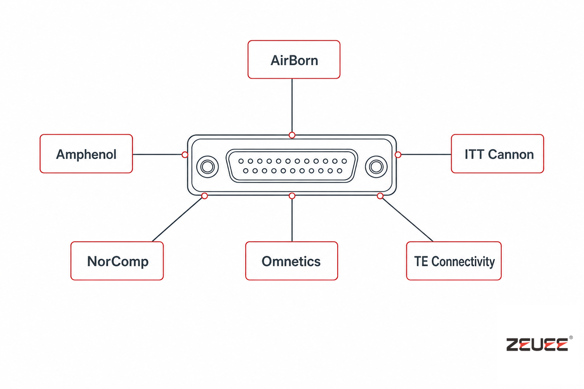
QPL-qualified micro-D suppliers form a genuinely short list; most of the named-brand supply in this space can be accounted for by AirBorn, Amphenol Pcd, Axon Cable, Bel Cinch, ITT Cannon, Molex, Nicomatic, the NorComp micro-d connector series, Omnetics Connector Corporation, PEI Genesis, TE Connectivity, and Glenair — each vendor runs its own micro-d connector series and, in several cases, a parallel d-sub series for the standard-pitch family. That concentration impacts lead time and price directly.
Distributor stock is lean for a niche, low-volume-per-SKU component: one QPL-qualified component in a commonly used configuration had only 11 parts in stock at a major distributor, with about five-week factory lead time to replenish stock. Non-stocked builds from various QPL suppliers quoted per-part prices in the neighborhood of $79 to $226 per unit depending on shell size and configuration, with lead times extending beyond whatever is already in stock — a gap driven by how few manufacturers keep tooling set up for less-common shell sizes, which matters most for aerospace and defense programs that can’t simply substitute a commercial part.
Key Factors to Consider Before You RFQ
- When in doubt, verify distributor stock before assuming standard configuration ships next week
- When ordering ask for the specific slash sheet and contact-construction callout-not simply “mil-dtl-83513”-
- When not stocked expect at least five weeks for factory replenishment
- Available from suppliers for lower cost and shorter lead time in commercial-off-the-shelf form are equivalent non-QPL parts. Make sure these parts will perform as intended before substituting them on a mission-critical system.
Acceptance Checklist: What to Ask Your Supplier For
When receiving parts, check for more than just shell dimensions and pin count against EIA-364 test method certifications. Request from your supplier a per-lot:
- ✔ Contact-construction certification (twist-pin vs. stamped) and make sure it matches your Purchase Order
- ✔ EIA-364-29 contact retention test report
- ✔ EIA-364-20 dielectric withstand test report
- ✔ Plating-thickness certification (per gold-microinch spec, not just “gold plated”)
- ✔ Slash-sheet number matching the drawing, not just the base mil-dtl-83513 part number
All five are a standard set of documents readily available from any QPL supplier and don’t require any exotic test equipment. What matters is that a supplier’s QPL ISO 9001 certification simply ensures that the supplier qualified the contact type, not that they consistently manufacture and certify to the correct slash sheet and contact construction type for a given part number. A supplier who balks at providing these documents is implicitly admitting they may not verify contact construction at all beyond shell dimensions when performing their own QPL-compliance inspections.
Which Industries Actually Need Micro-D?
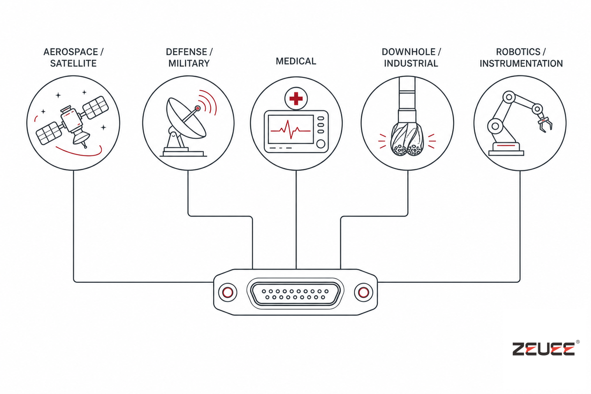
Micro-D connectors show up wherever space and weight constraints meet a reliability requirement that rules out ordinary standard connectors — military applications, demanding commercial applications, and anywhere a bad connection is expensive to fix in the field. That combination of tight tolerances and high consequence-of-failure is what earns Micro-D its premium over cheaper alternatives in these five industries.
| Industry | Typical use | Why Micro-D over cheaper alternatives |
|---|---|---|
| Aerospace & satellite | Avionics signal wiring, satellite payload panels | Mass budget + vacuum/vibration environment |
| Defense & military | Radar signal boards, ruggedized terminals | Shock/vibration + QPL traceability requirement |
| Medical | MRI sensor interfaces, surgical robot joints | High density in a tight, sterilizable enclosure |
| Downhole / industrial | Logging-while-drilling tools, ROV penetrators | Hermetic sealing under pressure |
| Robotics & instrumentation | Vision-system cabling, lab metrology | Density + reliable repeated mating cycles |
Beyond these five groups, if the environment is indeed kind-for instance, a benchtop instrument in a conditioned lab-a common commercial connector might well work just fine, and at a tiny price. That premium apply to cases where the price of a poor connection could be very high, not to every case by default.
Industry Outlook: The Five-Supplier Bottleneck and What It Means for Your BOM
Supplier concentration, not market growth, is the salient factor for buyers approaching the 2026 procurement cycle. About a dozen name-brand manufacturers account for the majority of the QPL micro-D supply, and a thin stock on the distributor shelves (single digits on many part numbers, lead times stretching to over five weeks at the factory) implies that a supplier single-source program inherently carries a schedule risk that the OEM may not have already priced. That risk often first manifests in a program requiring long-obsolete slash-sheet variants, or a significantly larger shell size where few manufacturers maintain inventory on the tooling itself – a symptom of the paucity of manufacturers carrying tooling for uncommon variants that ZEUEE sees whenever connector OEMs consider bringing their twist-pin contact production in-house instead of continuing to play exposed to a sparse supplier pool.
The base connector isn’t what’s technically changing – mil-dtl-83513G has been the latest revision since 2015, with no sunset language in the DLA documentation, though manufacturers are layering new capability on top of it: TE Connectivity’s MICRODOT line, for one, has added high-speed differential-pair and integrated-backshell Micro-D variants for data-heavy defense and aerospace links. It’s who’s going to build it and how fast. With some of the newer players not part of the “usual suspects” now getting into their own dedicated micro-D-class lines (in part to ease their own lead time pain for buyers), this is why you should seriously consider a second source alongside your QPL primary before the schedule pain makes that decision a necessity under duress for a 2026 program.
While Market-sizing estimates are useful context to have (one industry report forecasts the European high-speed micro-D category will grow to around $2.87B in 2034 from about $1.15B in 2025) as one researches category, it won’t shift a single sourcing choice. In sourcing and category intelligence the supplier-concentration and lead-time facts on the ground are the numbers that will actually impact your 2026 procurement plan.
Why We Write This
We compiled mil-dtl-83513 specification publicly available information with EIA-364 test method numbers and matched against other known-to-work contact technology information in combination with our own ZEUEE twist-pin line manufacturing documentation. Our own equipment make micro-D twist-pin contacts, so the contact resistance and shock-vibration comparisons above can be verified against our process data, and not taken from a third-party document as gospel. Reviewed by the Shenzhen Zeyu Intelligent Industrial Science Technology Co., Ltd. technical team
Frequently Asked Questions
Q: What’s the difference between Micro-D and Nano-D connectors?
View Answer
d-shaped connector have some other very small family members, such as micro-D and Nano-D. That difference is in how it’s made: Micro-D connectors have 0.050″ (1.27mm) spaced contacts, as spec’d to the mil-dtl-83513 spec. Nano-D connectors have 0.025″ (0.64mm) spacing between contacts, a factor of two reduction in contact spacing, and resulting roughly 1/4th the size and 1/8th the weight of an equivalent Micro-D; in use in, for example, the payload electronics for satellites, where every little space counts.
Q: Are Micro-D connectors male or female?
View Answer
Like their general d-sub connectors counterparts, micro-d connectors are available in keyed male and female connectors, or plug and receptacle as they’re sometimes referred to. Its plug, or male side, contains the pin contacts; the receptacle has the socket contacts, and its shield slides over the plug’s shield when mated. mil-dtl-83513 part numbers clearly identify plug and receptacle with slash-sheet suffix designations; be sure to consult the part drawing.
Q: What size are Micro-D contacts?
View Answer
Size #24 best fits micro-D contacts – machined or twist-pin, with a 0.050-inch (1.27 mm) pitch; about half the pitch of the 0.100-inch spacing found in a standard d-sub. Plastic shell versions can accommodate 9 to 51 contacts, while metal shells can handle up to 100, catering to everything from small sensor cable interconnects to high density signal busses.
Q: Can Micro-D connectors be hand-soldered, or do they need special tooling?
View Answer
Hand-soldering solder-cup style micro-D contacts is possible with a fine-tip soldering iron and magnifier, but the 0.050-inch pitch provides very little wiggle room – a pin holding fixture to align the contacts during assembly is highly recommended. If using crimp contacts, a specific crimp tool for that contact type will be required, rather than a generic crimper.
Q: How long is typical lead time for MIL-DTL-83513 QPL parts?
View Answer
Lead time depends on what stock is available at a given distributor and what configuration you need. As of this writing, one commonly-stocked QPL part number was shown as only 11 units on-hand with a lead time to the factory of roughly five weeks for anything beyond. Additional builds with other QPL providers and other configurations had lead times that pushed past two weeks and quoted prices in the range of $79 to $226 per unit, depending on shell size and termination method. Those of you designing programs requiring significant volumes of MIL-DTL-83513 contacts should definitely confirm lead times and stock levels directly with a QPL provider prior to committing to any project schedule.
Q: Are Micro-D connectors becoming obsolete, or still specified for new designs?
View Answer
Although there is no end-of-life on micro-d connectors – mil-dtl-83513 standard G (rev. 2015) remains at an active revision, and sales are growing according to distributors – they are still often specified for many of the latest aerospace, medical, and defense designs. Designers can expect the connectors to continue to be a standard offering for high-reliability applications requiring high contact density where space is at a premium for many years.
Are you a connector company evaluating whether it’s time to invest in in-house twist-pin contact production? ZEUEE’s six-machine twist-pin line was developed for the mil-dtl-83513 family of contacts.
References & Sources
- MIL-DTL-83513 Specification IndexDLA Land and Maritime
- EEE-INST-002 Parts Selection StandardNASA NEPP
- EIA-364-29E Contact Retention Test Method — ECIA / GlobalSpec Standards
- Testing (Electrical Connectors) — IEEE Xplore
- Ruggedness and Reliability Starts at the ContactConnector and Cable Assembly Supplier
- What are Micro-D Connectors?Connector and Cable Assembly Supplier
Related Articles
- DC Connector & Adapter Cable Types: A 2026 Buyer’s Guideanother connector-family buyer’s guide with the same anti-cannibalization structure
- Connector Assembly Machines Guidethe 5-step connector assembly sequence
- MIL-DTL-38999 Circular Connector Machinethe adjacent circular MIL-spec connector family
- MIL-DTL-26482 Connector Machineanother circular MIL-spec assembly line
- Connector Assembly Machines Hub24 twist-pin and MIL-spec assembly lines
WHY WE WRITE THIS
About ZEUEE Engineering Insights
ZEUEE shares technical guides based on real automation project experience. Since 2005, we have designed and manufactured non-standard automation equipment for connector assembly, wire harness production, robotic lines, vision inspection, and smart factory upgrades.
Founded in 2005
20,000 m² production base
120+ specialists
150+ R&D patents
ISO9001:2015 certified


![Automated Screwdriving: Torque & Cycle Time [Guide]](https://zeueeauto.com/wp-content/uploads/2026/10/automated-screwdriving-featured-150x150.png)