Get in touch with Zeyu lntelligent Industrial Company

Circular Connector Machine Guide: From Loose Parts to Tested Assemblies

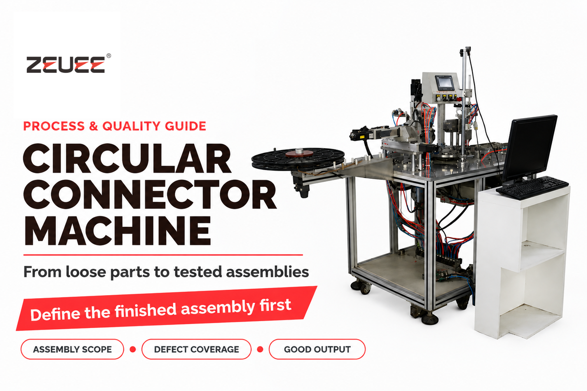
A Circular Connector Machine automates some operations for constructing round electrical connectors, such as feeding contacts, positioning inserts, and assembling and closing shells. It also checks the final part. Its output is a completed connector assembly, which meets defined checks, so determine the finished product before comparing speeds or levels of automation of the machine.
A contact can conduct electricity while sitting insecurely in its housing. A fast insertion station can also wait for a slower cable preparation step. Those two problems explain why the first step of a useful machine assessment is to define the assembly boundary and identify the defects that must be detected. This assessment covers cost per good piece and changeovers.
Circular Connector Machine: Scope and Finished Outputs
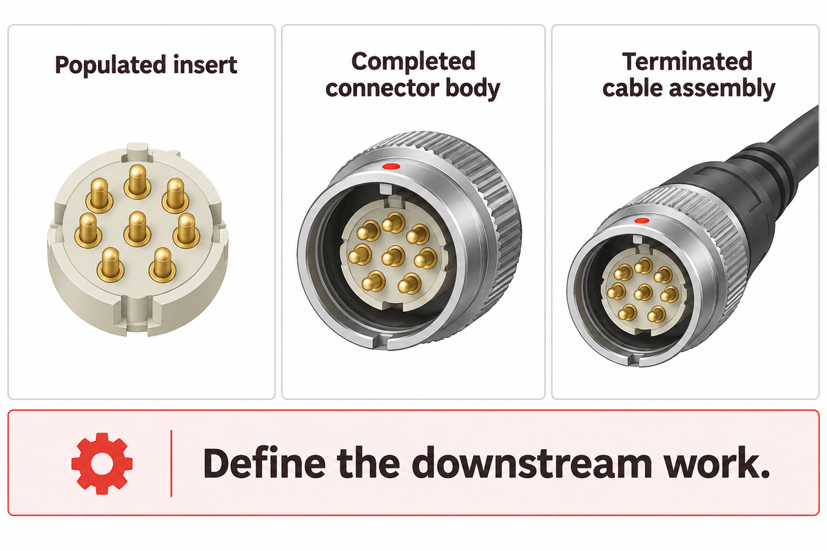
Circular connector assembly machines can create a populated insert, a completed connector body, or a terminated cable assembly. These outputs depend on different operations and inspection points. Determine the incoming components and the required output assembly state to establish whether functions like feeding, crimping, sealing or overmolding need to be done by the machine.
For example, an insert loaded with loose contacts requires a shell, and possibly other components, to be completed. A completed cable assembly requires the preparation and termination of the conductor. Some products come with contacts already installed, which changes the remaining assembly work. The surrounding equipment categories are covered in the connector assembly equipment types guide.
Specify a tangible handoff: “populated insert ready for shell assembly” is more useful than “assembled connector.” State what remains to be done downstream, who does it and where final acceptance occurs. If both ends of the cable are assembled, state whether the counter counts cables or individual connector ends.
Frisimos presents a good example of the difference between an integrated assembly line and a separate insertion cell. Its automatic circular connector assembly line includes cable preparation, crimping, insertion and overmolding, and assembly on one or both cable ends. Describing the line this way defines that line’s scope; a separate contact insertion cell is a different production device.
Connector Geometry, Terminations and Tooling Fit
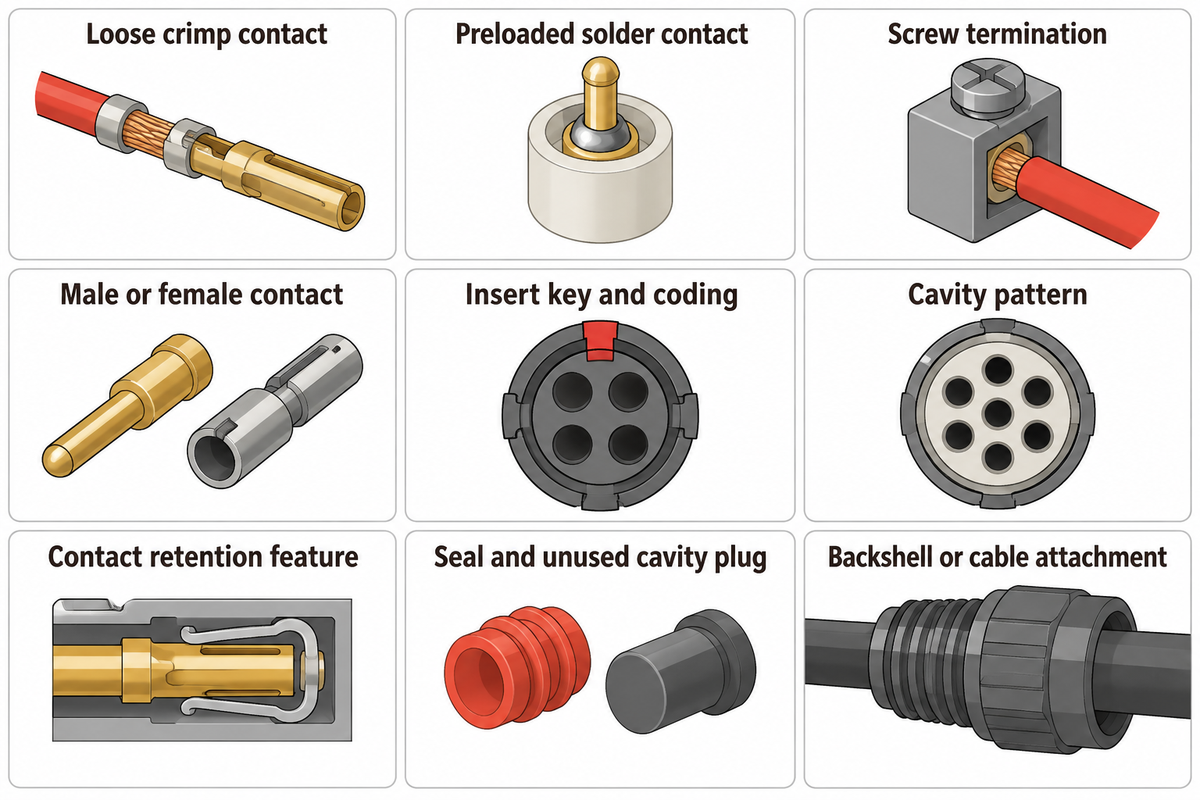
The assembly process isn’t determined by the circular shell alone. The contact design, cavity layout, termination method, and access to the locking feature determine how the part can be handled. Match the tooling to the complete connector drawing and component revision, including the view used for contact numbering and the required final orientation.
Plugs and panel receptacles require their own fixture definitions, even if they share a mating interface. Specify the support surfaces for each plastic or metal housing and check that the fixture doesn’t block the assembly path. For examples of locking systems, see Binder’s subminiature connector range: screw, bayonet, snap-in and push-pull.
If mating is part of the acceptance cycle, define the motion for tooling (e.g. for a threaded interface, tooling provides rotation; for a bayonet, it provides engagement and locking travel; for a push-pull interface, it provides axial engagement and latch confirmation). Use product instructions to specify the actual motion, limits and verification method. Mating may remain a separate operation. Inserting contacts alone doesn’t establish that the coupling works.
Even familiar labels need unpacking. TE lists an M12 field-installable connector with screw termination in its circular connector range. The assembly instructions by Amphenol Socapex describe PT/451 solder contacts supplied mounted and non-removable. Neither product follows the same sequence as loose crimp contacts that are inserted after termination.
| Feature to identify | Process consequence | What to resolve before tooling |
|---|---|---|
| Loose crimp contact | Terminate the wire before insertion where the product requires it | Contact, wire and applicator combination |
| Preloaded solder contact | Termination occurs with the contact already installed | Access and thermal process requirements |
| Screw termination | Conductor placement and fastening replace crimp insertion | Wire preparation and fastening specification |
| Male or female contact | Gripping and probe access differ | Surfaces permitted for handling |
| Insert key and coding | The nest must establish angular position | Drawing datum and permitted orientations |
| Cavity pattern | The insertion path and wiring map change | Mating-face versus termination-side view |
| Contact retention feature | Seating and locking need distinct checks | Approved retention test method |
| Seal and unused cavity plug | Additional placement operations may be necessary | Presence, orientation and seating criteria |
| Backshell or cable attachment | Assembly access and fixture clearance change | Final assembly envelope and strain relief |
Use pin and socket contact handling to study the related small-part operations in more detail. For a narrower starting point, use the guide for MIL-DTL-38999 connector families.
If the cavity pattern changes in a similar shell, don’t assume that a part loaded with one recipe will work for the other. A good contact may be placed in the wrong cavity by accurate motion. Check mapping to the drawing before the first assembly. This will help catch mapping errors that tighter positioning alone cannot correct. Ensure the physical key fits the drawing, verify the wiring map and retain a labeled part for reference. Update the inspection program alongside insertion coordinates. Leaving the electrical test map unchanged can lead to a false pass or a false rejection.
Connector Assembly Process: Feeding to Unloading
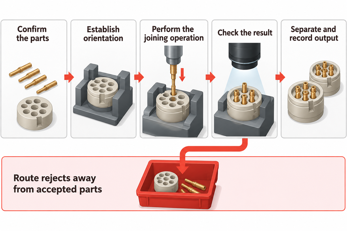
A connector assembly sequence determines the identity, orientation, positioning, and acceptance of components at each stage. Feeding puts a usable component into the system; fixtures establish the assembly datum. Controlled motion performs the assembly; inspection checks the specified result. Reject handling and unloading establish a barrier between the good product and bad product and protect the production record.
How does a circular connector machine work?
A circular connector machine is tied to a connector configuration. Frisimos describes its semi-automatic line as assembling circular connectors to multi-core cables with 3, 4, 5 and up to 8 wires. Components are presented by feeders or operators. A fixture locates the insert or shell, and an assembly mechanism inserts the contact or subassembly. A sensor verifies part presence. A press, fastening tool, or downstream station completes the joining operation.
A crimping machine forms the contact termination. An assembly machine positions and secures the contact and other connector components. Crimping can be a module within an integrated assembly line. A standalone crimping machine doesn’t by itself populate the connector housing or verify its mechanical locks.
The sequence is product-specific. Wire preparation and connector crimping equipment may be upstream from the assembly cell. Overmolding can follow the electrical assembly. Explicitly defining boundaries keeps a seemingly attractive cycle-time figure from excluding the slowest task.
- Confirm the parts — Match the component identity and recipe before loading.
- Establish orientation — Locate the key, cavity pattern and assembly datum.
- Perform the joining operation — Insert, press or fasten according to the product process.
- Check the result — Apply the checks assigned to that operation and product.
- Separate and record output — Route rejects away from accepted parts and save the required results.
Feeding comes before motion speed. An unstable presentation can require repeated attempts or damage a contact. It can also interrupt the next station. Observe presentation and transfer using production components spanning the permissible dimensional variation. Inspect the part after handling to tell if damage was caused by the feeder or if the part was damaged during insertion.
A 2024 Machines paper on connector pin and seal assembly describes a design for closing unused connector cavities and integrates feeding and inspection. The closure pins close unused cavities rather than serve as contacts. According to the authors, the equipment hadn’t reached production, so the calculations describe design estimates rather than demonstrated line output.
Connector Inspection: Match Each Defect to a Test
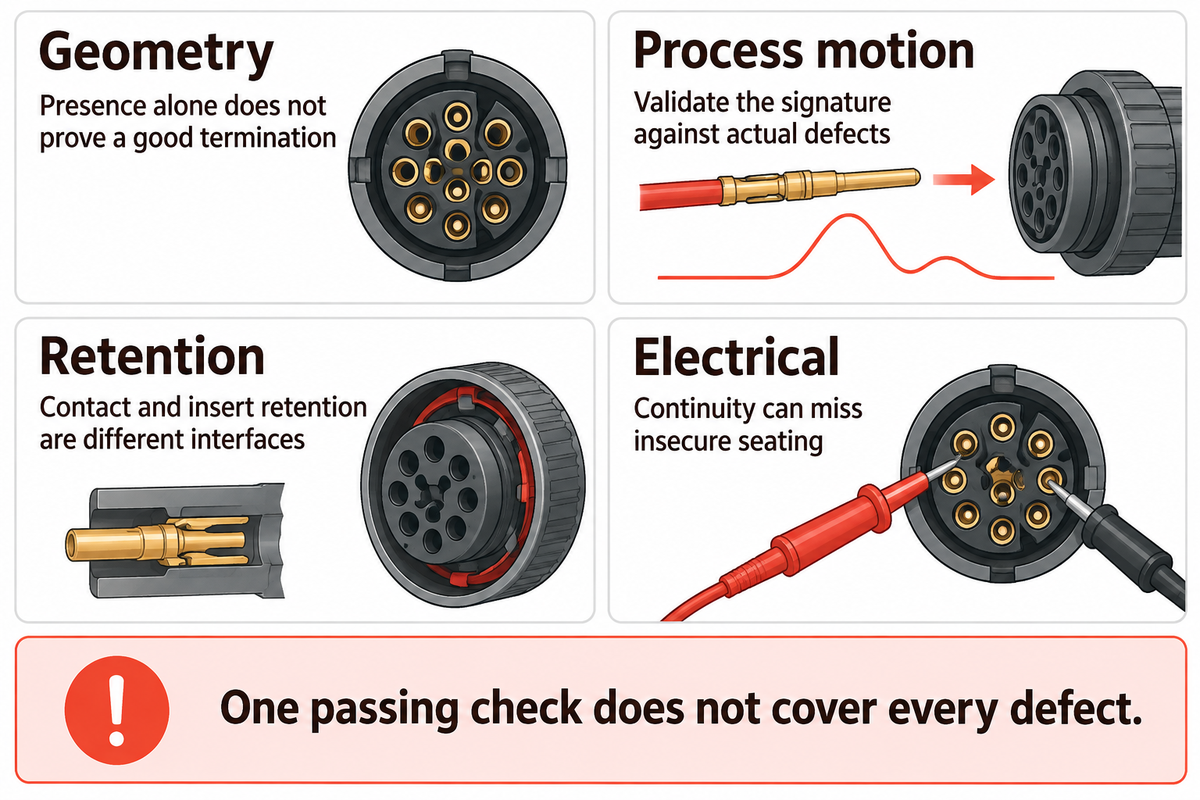
Connector inspection requires separate evidence for visible geometry, assembly motion, mechanical retention, and electrical performance. A successful result in one category can’t establish every other category. Identify what a given inspection can’t see. Assign each credible defect to a check and specify how failed assemblies leave the production flow.
NASA’s Scout launch-vehicle lesson describes contacts that recessed because they had not locked correctly, including cases involving damaged retention clips. Its practical recommendation is to address replaceable contacts prior to mating.
“Perform a push test prior to mating to detect and screen for unlocked contacts where the connector has replaceable contacts.”
National Aeronautics and Space Administration, Recessed Electrical Pins, 1995
4-View Defect-to-Test Map
Use this map to discuss coverage of specific inspections with quality and production teams. The product specification determines test force, electrical settings, sampling frequency and permitted result.
| Possible defect | Candidate check | Remaining blind spot |
|---|---|---|
| Missing contact | Geometry: cavity presence inspection | Presence alone does not prove a good termination |
| Bent exposed pin | Geometry: suitable camera view or dimensional check | Hidden damage may be outside the view |
| Wrong cavity assignment | Electrical: programmed wiring-map test | The test map itself must match the drawing |
| Abnormal insertion event | Process motion: force and displacement monitoring | A normal signature needs validation against actual defects |
| Contact not locked | Retention: approved contact retention check | Electrical continuity alone can miss insecure seating |
| Insert insecure in housing | Retention: insert-to-housing axial test | Contact retention measures a different interface |
| Weak wire-to-contact crimp | Retention: specified destructive crimp pull test on samples | Tested samples are consumed; other checks cover production parts |
| Open circuit or unintended connection | Electrical: continuity and wiring tests | These do not establish insulation withstand capability |
| Insulation defect | Electrical: specified insulation or dielectric test | Correct test settings and acceptance limits remain essential |
IEC 60512-15-1 details contact retention, while IEC 60512-15-2 details insert retention in the housing. IEC 60512-1 requires the detail product specification to describe which tests apply, their levels and permissible limits of performance.
Another NASA source, its cable-assembly crimp pull-test study, identifies spare-contact cost and availability as constraints, since pull testing is destructive. Include those samples in the quality plan and cost model. Don’t consider pull tested samples as saleable output. For example, imagine a hypothetical test fixture where a spring-loaded probe touches a partially seated contact.
The circuit passes the test, yet the contact can move when the mating connector arrives. Raising the electrical test count would repeat the same blind spot. WEIPU’s factory-audit checklist lists 100% continuity checks and insulation-resistance testing at 500 V DC as evidence to request; the actual settings still depend on the connector specification. The quality engineer would check the retention requirement, specify an acceptable mechanical test and verify that defective samples would be rejected. The production team would specify reject routing and recovery after a stop. This is why connector inspection automation should be defined by defect coverage, as opposed to a generic “tested” label or a camera count.
Semi-Automatic Cells and Fully Automatic Lines
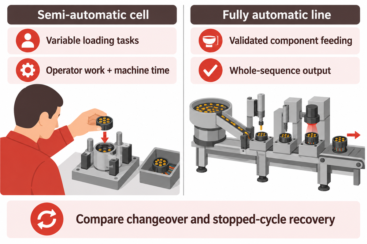
There are trade-offs among automatic cells. Semi-automatic cells retain some tasks such as loading or cable handling, while fully automatic cells automate more tasks. Choose the division of work to accommodate product variation, difficulty of handling, and sustained demand. Automation of longer processes may offer little overall benefit when largely dominated by loading or changeover work.
Which circular connector machine is better for mixed production?
For mixed production, an operator-assisted cell can be a good starting point if components or cable presentations change frequently; compare the complete changeover and recovery workload before comparing nominal cycle times. More integrated lines become attractive with stable production runs.
Semi-automatic cell
- Assign variable loading tasks to the operator.
- Measure operator work together with machine time.
- Keep repeatable joining and checking under machine control.
Fully automatic line
- Validate component feeding across the intended product family.
- Measure output through the whole linked sequence.
- Plan automatic rejection and practical fault recovery.
A 2020 Friedrich-Alexander-Universität Erlangen-Nürnberg research record analyzes task allocation between workers and automation in wire-assembly production, using weighted criteria, and makes final-assembly qualitative conclusions.
Assess changeover and stopped-cycle recovery by the operator work required, the identification of unfinished assemblies, and the separation of rejected parts from the good-parts container. Demonstrate both changeover and stopped-cycle recovery to reveal effects on labor requirements and quality that smooth operation can mask.
Connector Output and Cost per Good Piece
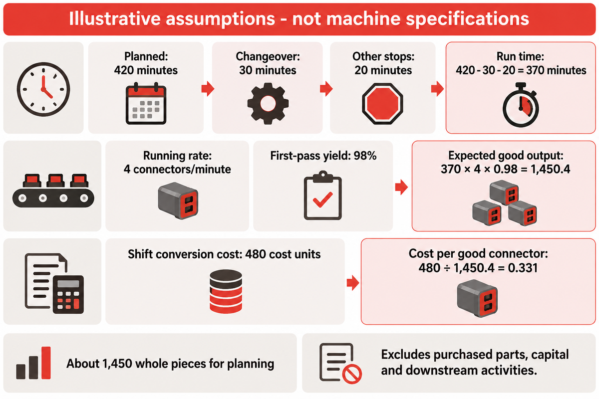
Connector output is a function of time available to run and the running rate and first-pass yield. Track pins, connector ends and completed cable assemblies as separate output units. Deduct each loss only once and divide the relevant production cost by accepted output to compare processes on the same basis.
The University of Tennessee Center for Industrial Services separates availability, performance and quality in their equipment effectiveness guide. Using the same distinction helps avoid a common estimating error: deducting small stops twice when the observed running rate already includes them.
Convert pins to pieces before comparing capacity
Let’s say a feeder supplies 24 pins per minute. With 6 pins per connector, the feeding ceiling is 24 ÷ 6 = 4 connectors per minute. Changing the product to 8 pins per connector, that same feeder supplies only 3 connectors per minute. These assumed figures illustrate the conversion from pins to connectors. Other operations can reduce the finished output even further.
For tasks which must be performed sequentially within a single machine cycle, the total time for all tasks in the sequence sets the cycle time. For tasks which can be performed in parallel, the effect of the constraints in the slowest parallel path determines steady output, while buffers and transfer behaviors also affect the outcome. Creating a parallel path which includes a limiting station only improves steady output if that station limits the real line. Before paying for another insertion module, check loading, inspection and unloading.
Work through an assumed production shift
| Input or result | Value | Meaning |
|---|---|---|
| Planned production time | 420 minutes | Time scheduled for production |
| Changeover time | 30 minutes | Deducted within planned time |
| Other stopped time | 20 minutes | Separate from changeovers |
| Run time | 370 minutes | 420 − 30 − 20 |
| Achieved running rate | 4 connectors/minute | Includes the observed running-speed losses |
| First-pass yield | 98% | Accepted without rework |
| Expected good output | 1,450.4 connectors | 370 × 4 × 0.98; about 1,450 whole pieces for planning |
| Shift conversion cost | 480 cost units | Assumed labor, energy, allocated maintenance and tooling cost |
| Conversion cost per good connector | 0.331 cost units | 480 ÷ 1,450.4, rounded |
Fractional outputs in this example represent expected values, not physical part counts. This example doesn’t include purchased parts, capital costs, or downstream activities. Add these explicitly if the comparison intends to show total manufacturing costs. Keep rework and destructive test costs, and be consistent in including or excluding these costs for alternatives being compared.
When comparing two proposals with the same machine rate, consider the impact of fixturing and first-piece approvals in a mixed product shift. Run time is calculated as planned production time minus stop time, which includes planned changeovers and unplanned stops. Thus, a proposal with longer fixturing and first-piece approvals can generate less acceptable output. Using the same time available for production, compare the accepted output assumed in each proposal and test whether those assumptions are reasonable during a production run. If improved fixtures or better recipes reduce changeover time, update that input so the improvement remains traceable.
Changeovers, Maintenance and Recurring Defects
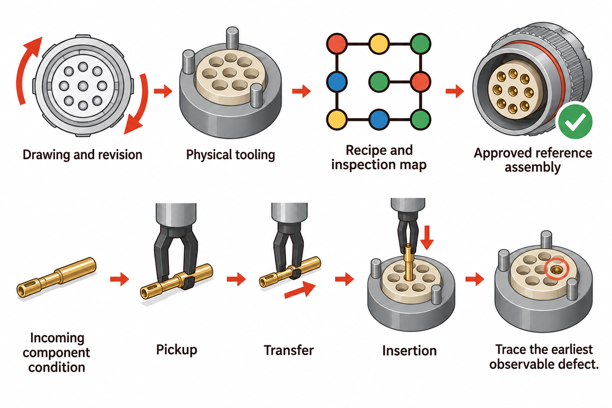
Reliable changeovers include the complete product setup, including fixture, feeder, tooling, recipe and the inspection program. Maintenance should be done based on observed failure modes and in accordance with the equipment manufacturer’s instructions. When a defect recurs, find the first operation where a good component becomes defective, prior to changing any force settings, positions or acceptance criteria.
Keep first piece records for each approved configuration, linking drawings and revisions, electrical test maps and tooling. NASA describes a project that performed a push test on each contact after initial wiring and connector modifications. Inspect changed assemblies while the feature is still accessible. Waiting until the shell is closed may hide the cause. Deformed or broken retention clips were a frequent cause of improper locking in that project as well.
For a bent pin, consider all stages: incoming component condition, pickup, transfer and insertion. For an intermittent contact back-out, inspect the retention feature and the approved seating check. Improper locking with damaged retention clips is discussed in NASA’s recessed-pin lesson. Increasing the insertion force may simply further damage the interface.
Do
- Compare rejected parts with an approved reference assembly.
- Trace the defect to its earliest observable stage.
- Recheck the recipe and inspection map after tooling changes.
Don’t
- Do not raise force limits simply to suppress rejects.
- Do not use an electrical pass as proof of every mechanical feature.
- Do not return interrupted assemblies to production without a defined check.
Record the adjustment and the outcome so that the next operator isn’t wasting time performing an unsuccessful adjustment. Stable production comes from a controlled setup and an understood defect, and not from progressively broadening acceptance limits.
Integration and Utility Requirements
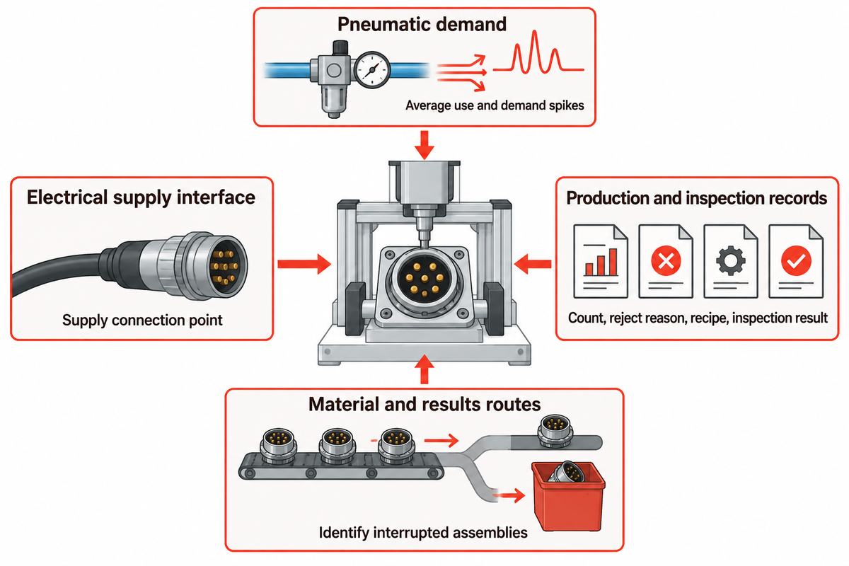
Machine integration requires a defined electrical supply, provision for any pneumatic demand, safe operating interfaces, and usable routes for materials and results. Determine these requirements for the configured equipment. A generic figure for voltage or air pressure can’t adequately describe every combination of feeders, joining tools, inspection devices, and downstream processes.
IEC 60204-1 covers machinery electrical equipment starting at the supply connection point. Use that interface to define supply characteristics, isolation, protective measures and the responsibilities of the machine builder and site installer.
For pneumatic equipment, separate average usage from high demand spikes. The Australian Government’s compressed-air guidance states that a receiver can even out short-term demand spikes. It also notes that electric alternatives may need additional local electrical supply even when total site electricity use decreases. Because of this, utilities also need to be reviewed as part of the configuration.
State which results have to leave the machine: production count, reject reason, product recipe, and any required inspection record. Agree on how an interrupted assembly is identified after power loss or communication failure. A record linking an accepted part or batch to the process that made it is useful.
Key takeaway
Define the finished assembly, assign a check to each important defect and compare output in accepted pieces. Those decisions connect the connector drawing to a useful machine specification.
The connector drawings, samples of the components, the proposed output scope and required checks must be sent to the ZEUEE automation team for the equipment discussion. The next step to review the company’s equipment offering in relation to application is the Circular Connector Machine solution page.
Circular Connector Machine FAQ
What is an M8 connector, and does its name define assembly tooling?
M8 identifies a circular connector interface size family; it doesn’t completely define assembly tooling. Use the full product drawing and part numbers to establish contact arrangement, coding, termination method and component geometry. Those details determine the fixture datum, accessible handling surfaces and required assembly sequence, including which components arrive already installed.
Can one circular connector machine handle different pin counts?
One machine may support different pin counts when its fixtures, feeding system, motion program and inspection setup are designed for those configurations. A recipe change alone may be insufficient. Compare cavity patterns, contact types and access, then demonstrate the changeover and first-piece checks using each intended configuration before treating the range as established capability.
Does a passed continuity test prove contact retention?
No. Continuity establishes an electrical path under the test conditions, while retention concerns whether a contact remains mechanically secured. A partially seated contact may still conduct during a test. Use the product’s specified retention method and acceptance criteria, and validate the inspection arrangement with representative defects rather than assuming that an electrical pass covers mechanical locking.
Why is a circular connector machine not working consistently?
Check component presentation, fixture location, tooling condition, recipe selection and inspection settings. Find where the defect first appears by comparing incoming parts with intermediate assemblies. Change one controlled factor at a time, then verify the result against approved product requirements.
Does circular connector assembly always include overmolding?
No. Overmolding belongs only to products and production scopes that require it. A machine may instead deliver a populated insert, a connector body or a mechanically assembled cable termination. If molding is included, identify which checks must happen before encapsulation makes internal features inaccessible. Then specify the handoff to molding and any checks required afterward. Include that downstream workload in output comparisons whenever the agreed finished product includes the molded cable end.
Is a circular connector machine price available without samples?
A supplier may estimate a budget from drawings and a process description. Samples help establish feeding, handling and inspection requirements. Ask whether tooling, variants, tests, integration, installation and spare parts are included, and identify assumptions that still need a trial.
Does a circular connector machine make a connector compliant with a standard?
The machine alone doesn’t establish product conformity. The connector specification determines relevant construction and test requirements, and the production process must provide the appropriate evidence. Agree the applicable requirements, acceptance limits and records for the actual product. Distinguish machinery electrical requirements from connector performance requirements: they address different equipment and interfaces. A useful production record identifies the tested part or batch, the applicable test recipe and the result, with traceability suited to the application.
Discuss your connector assembly process
Share the part drawings and the checks your finished assembly must pass. Use them to define the equipment scope and a representative trial.
References & Sources
- Curralo and colleagues, Machines research on connector pin and seal assembly, 2024.
- National Aeronautics and Space Administration, Recessed Electrical Pins, 1995.
- International Electrotechnical Commission, IEC 60512-15-1: contact retention in insert and IEC 60512-15-2: insert retention in housing, public scopes.
- Estonian Centre for Standardisation and Accreditation, IEC 60512-1:2018 public scope.
- National Aeronautics and Space Administration, cable-assembly crimp pull-test research record.
- Friedrich-Alexander-Universität Erlangen-Nürnberg, research record on human and automation task allocation in wire-assembly production, 2020.
- University of Tennessee Center for Industrial Services, OEE Implementation Guide.
- International Electrotechnical Commission, IEC 60204-1 machinery electrical-equipment scope.
- Australian Government, Compressed air equipment guidance.
WHY WE WRITE THIS
About ZEUEE Engineering Insights
ZEUEE shares technical guides based on real automation project experience. Since 2005, we have designed and manufactured non-standard automation equipment for connector assembly, wire harness production, robotic lines, vision inspection, and smart factory upgrades.
Founded in 2005
20,000 m² production base
120+ specialists
150+ R&D patents
ISO9001:2015 certified