Get in touch with Zeyu lntelligent Industrial Company

Pin & Socket Contacts Machine: Contact-to-Housing Guide

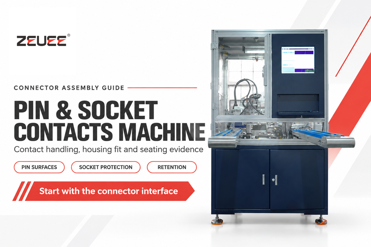
The specification for a Pin & Socket Contacts Machine must identify the parts it will handle. In a completed cycle, there may be a contact present, but its retaining feature may not be in position. The engineering task is to move the correct contact into the correct cavity, preserve its functional surfaces and demonstrate the required final condition.
This guide follows those interfaces from incoming parts to accepted assemblies. It covers the differences between pin and socket handling, the drawings that define tooling contact, the evidence needed to establish seating and retention, and the samples that make a machine trial useful. For the broader equipment cycle and automation options, see the pin insertion machine guide.
What does a pin and socket contacts machine assemble?
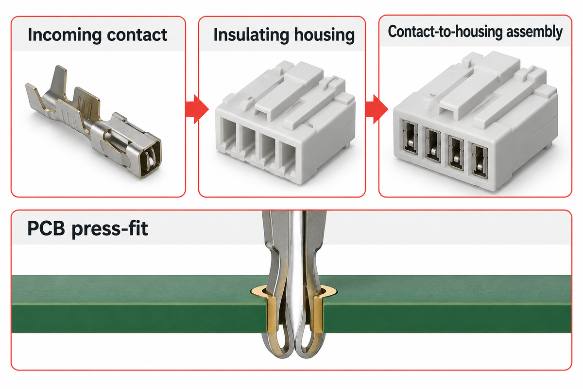
In this machine, the input may be loose contacts or contacts mounted on a carrier, or contacts that are crimped to a wire. The output is a defined contact-to-housing assembly. The exact preparation state matters because the machine’s handling system must accommodate everything that moves with the contact, including wire, seals and carrier remnants.
The phrase also appears around adjacent processes. Contact manufacturing forms the metal component. Depinning with a terminal pin removal tool removes a contact for repair. Crimping joins an appropriate terminal to a conductor. An assembly specification should identify which of these operations is included, which is performed upstream, and what condition the parts arrive in.
Printed-circuit-board press-fit has a distinct application. TE Connectivity’s pin insertion and press-fit equipment brochure describes board-oriented platforms and product-specific tooling. It is a useful equipment reference, but its board-support arrangements and insertion checks need their own application review before being applied to a contact entering a plastic housing.
Start an input-and-output sketch. Show the contact, the housing cavity, the direction of insertion and the completed assembly. Add any wire or seal present during insertion. That sketch will provide the equipment supplier a defined boundary for quotation and will also show absent upstream operations.
Pin contacts and socket contacts need different handling reviews
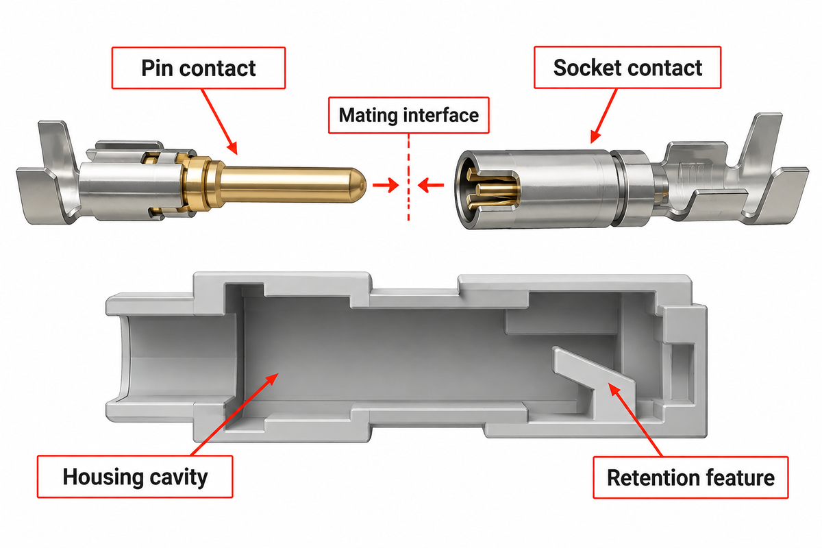
A contact that needs to project will be a pin. A socket receives the mating contact and may contain spring elements that establish contact pressure. Their external handling features, retaining structures and assembly orientation are product-specific. A family name or a similar outside diameter is insufficient to establish that the same gripper, guide or insertion tool can handle both.
Which surfaces on a pin need protection?
Ask the contact manufacturer to show the mating zone, the permissible pushing surface and anything that helps determine the orientation of the pin. Also review how the pin is supported and how it’s guided as it approaches the cavity. Take a representative sample of the contact and inspect if there are any marks left on it after feeding and after insertion. A mark left upstream of the insertion station should be identified so it can be differentiated from a mark left by the insertion station.
A photograph of a straight pin after a successful cycle is only part of the evidence. The trial record should identify the exact contact and housing revisions, the inspection location and the criterion used to judge surface condition. This helps the quality team distinguish an allowed handling mark from damage to a functional surface.
What changes when the part is a socket?
For a socket, the review must also include the internal contact structure and the receiving opening. Determine whether the proposed tool approaches the socket mouth, supports its outside body or pushes from another documented feature. The machine supplier should show how the tool path avoids unintended contact with spring elements.
The Molex PowerWize application specification illustrates how housing geometry and locking fingers govern assembly of a particular crimp-socket system. The document provides details for a specific product family. Obtain equivalent documents for the quoted contact and housing pairs.
For a broader comparison of machined, stamped and specialized contact families, use the connector contact types guide. The focus of the review is on how the selected components are handled.
Separate mating, seating and retention evidence
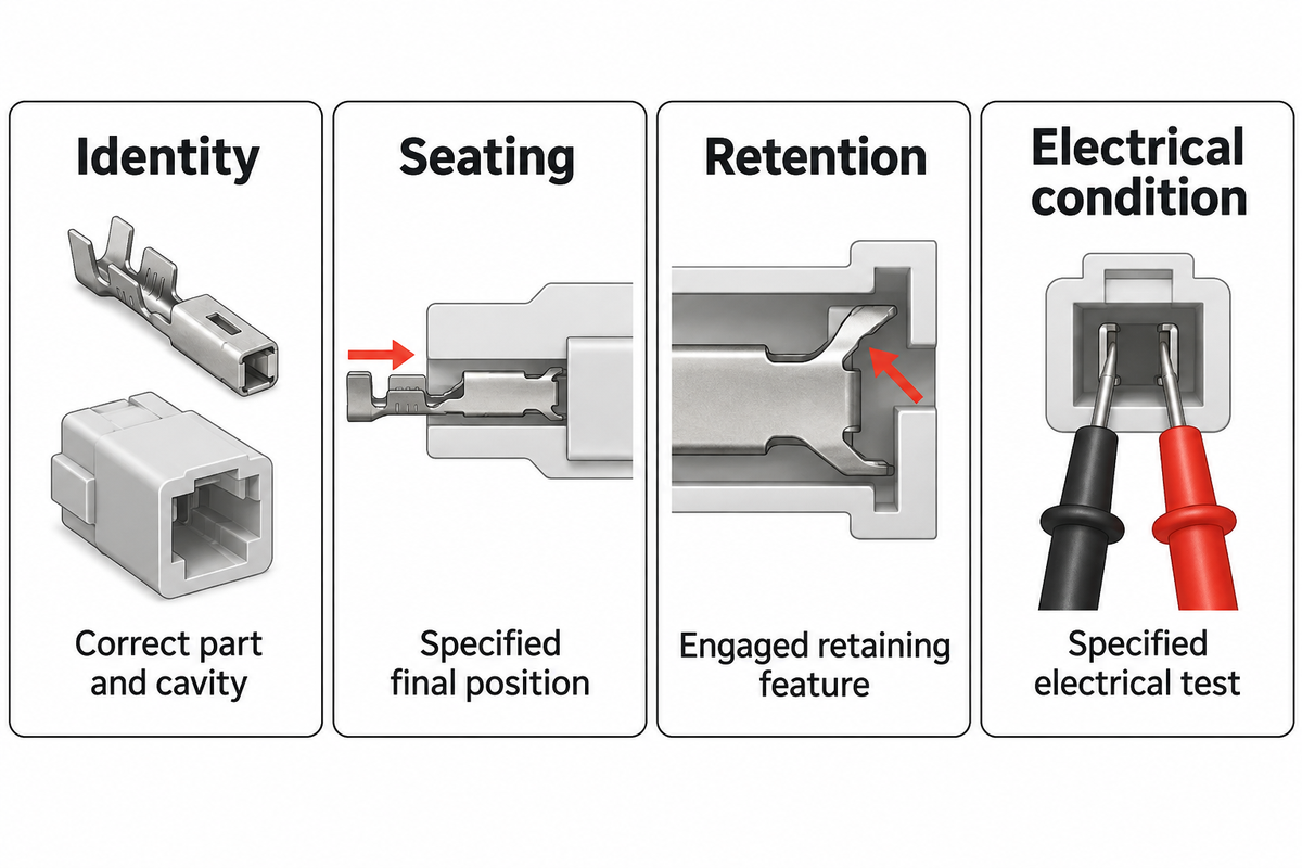
Mating addresses the contact interface between the connector halves. The method in IEC 60512-13-1 measures forces involved in connector mating and separation. Seating is the contact reaching its specified assembled position. Retention concerns the features that keep it in the housing under the applicable test conditions. IEC 60512-15-1 addresses axial loading of the contact-retaining system. A production inspection plan should state which question each measurement answers. At another interface, IEC 60512-15-2 examines axial retention of an insert within a housing when called for by the product specification.
Molex’s contact retention guide distinguishes terminal-level retention from connector-level retention. A terminal lance or a secondary terminal lock acts at an interface different from a latch holding the two connector halves together. Recording that distinction prevents a connector mating test from being treated as evidence for every individual terminal lock.
| Question | Evidence to define | Record to retain |
|---|---|---|
| Is the correct contact in the correct cavity? | Part identity, cavity assignment and orientation check | Part revision, recipe and inspection result |
| Has the contact reached its specified position? | Position, protrusion or other specified seating indication | Measurement location, limit and result |
| Is the retaining feature engaged? | Inspection or mechanical check defined for that connector | Method, sample identity and outcome |
| Does the completed assembly meet its electrical requirement? | The electrical test required by the product specification | Test configuration, limits and result |
Use this difference when discussing inspection equipment. A camera can show presence or orientation. A displacement measurement can show final position. Their role in a retention decision is defined by the connector design and what it allows the test to reveal. The quote should name the feature under test and what failure of that feature is being checked for.
Build a contact-to-cavity evidence register
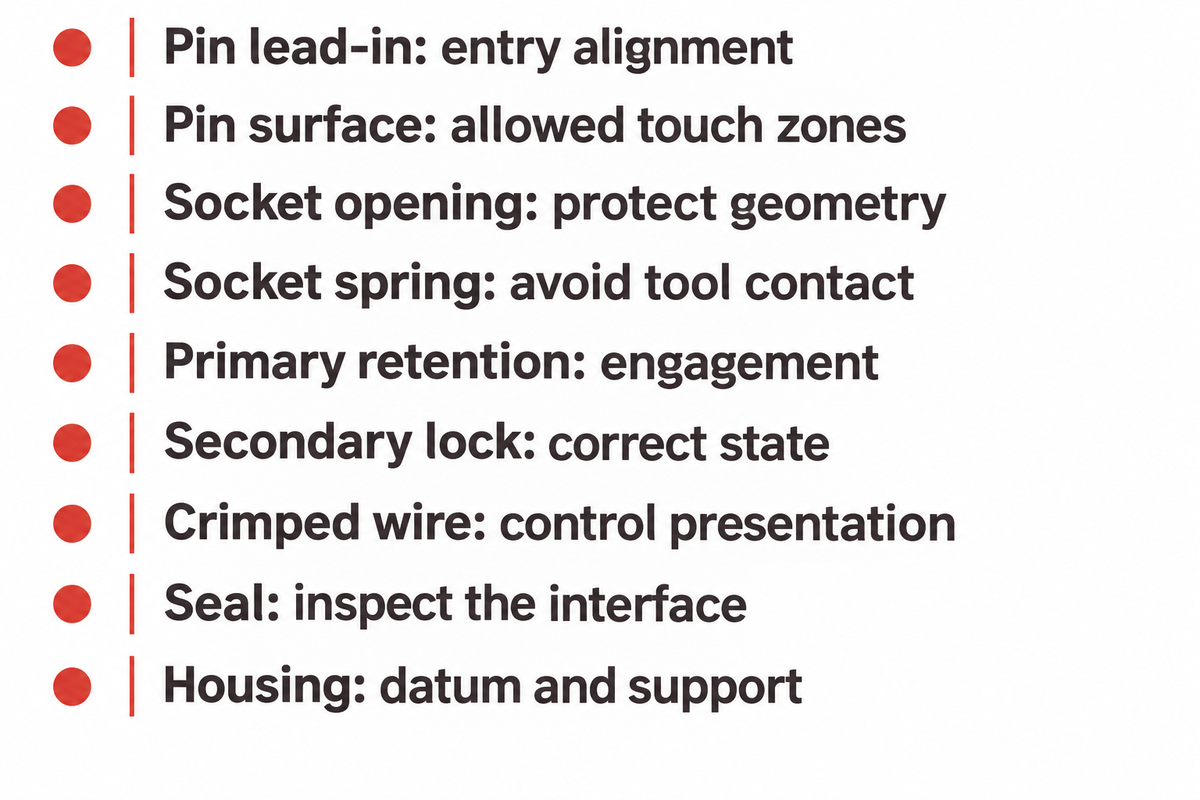
A useful tooling review follows the features that can be touched, damaged or assembled incorrectly. This section is a project-planning tool. Engineering defines the handling restrictions, quality defines the evidence, and procurement checks that the quoted tooling and trial include those requirements.
| Feature under review | Handling question | Potential problem to investigate | Evidence for the trial |
|---|---|---|---|
| Pin lead-in | How does the tip enter the guide and cavity? | Off-axis entry or tip damage | Entry views and inspected samples |
| Pin mating surface | Where may the feeder or gripper touch? | Marks on a functional surface | Documented touch zones and surface inspection |
| Socket opening | How is the opening kept clear during transfer? | Deformation or trapped material | Before-and-after inspection of the opening |
| Socket spring structure | Can tooling enter or load the spring area? | Unintended spring contact or displacement | Tool-path review and applicable functional checks |
| Primary retaining feature | How is engagement established? | Contact present but insufficiently retained | Connector-specific engagement and retention evidence |
| Secondary lock | When is it installed and how is its state checked? | Incomplete lock state | Specified lock-position inspection |
| Crimped wire | How are the contact and trailing wire presented? | Wire drag, orientation change or crimp interference | Trial samples using the intended wire preparation |
| Seal interface | What orientation and entry path does the specification require? | Seal damage or unexpected insertion resistance | Inspection of representative sealed assemblies |
| Housing datum and support | Which surfaces locate the housing and take the assembly load? | Housing movement or damage near the cavity | Fixture drawing, position checks and housing inspection |
Take the engagement check from the connector’s own documents, not from a generic force limit. The Application Specification for Squba defines its own terminal orientation and seating. A project involving another family needs that family’s instructions and drawings.
Purchasing can tie each line to a requirement in the supplier’s scope. If a retention check is required, the proposal should state whether equipment performs it, whether it’s a sampled quality operation and which results are delivered. An unassigned check becomes a handover dispute, even if the equipment is moving the parts correctly.
Prepare samples that reveal pin and socket differences
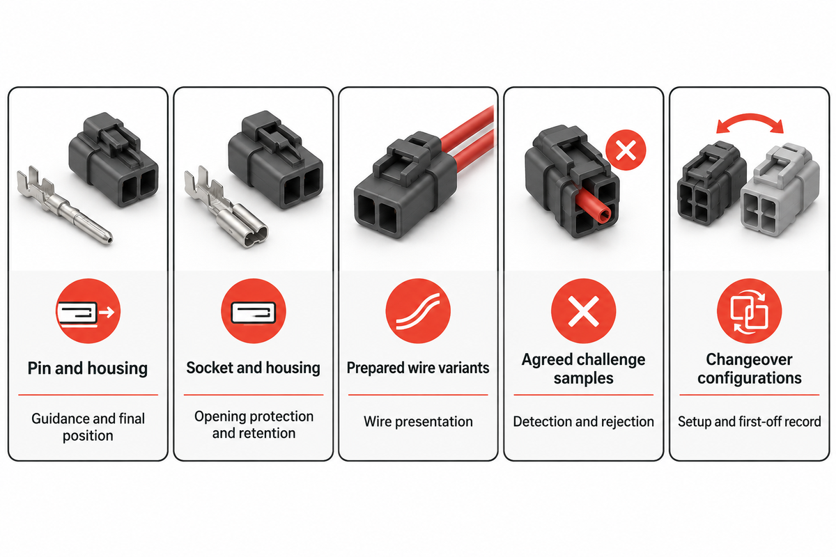
A sample set should represent the declared production configuration. Include the relevant pin and socket part numbers, matching housings, their drawing revisions and the actual incoming preparation. Loose demonstration contacts alone cannot establish how the same station handles wire-attached contacts, seals or a different supply format. The separate contact and housing entries in the PowerWize application document show why a family name needs to be resolved into the actual components for a trial.
Organize samples by configuration instead of combining them in one container. Be sure to label the variant of contact, housing, wire, or preparation and the recipe intended. The supplier can then connect each test result to an identifiable assembly. The quality team also has a means to investigate a failed sample after the test.
| Sample group | Purpose | Evidence to request |
|---|---|---|
| Pin and its matching housing | Review guidance, pushing surface and final position | Tool contact map and inspected completed parts |
| Socket and its matching housing | Review opening protection and the retaining arrangement | Socket inspection and specified seating evidence |
| Prepared wire-attached variants | Evaluate wire presentation and handling through insertion | Representative runs with identified wire preparation |
| Agreed incorrect or incomplete assemblies | Challenge the proposed detection and rejection functions | Expected response, observed response and disposition |
| Changeover configurations | Establish which tooling and recipe elements change | Change-part list, setup record and first-off approval |
Agree to the challenge parts and test sequence prior to the demonstration. A deliberately incorrect part needs an expected response and a controlled handling procedure. The goal is to define detection coverage. A successful normal sample and a rejected challenge sample answer different questions.
Agreement for sample ownership and returns should be within the same test plan. Identify the parts retained by the supplier for setup and troubleshooting, and the parts, images and records returned to the buyer. This simplifies comparisons between factory trials and the machine in use.
Evaluate seating problems at the affected interface
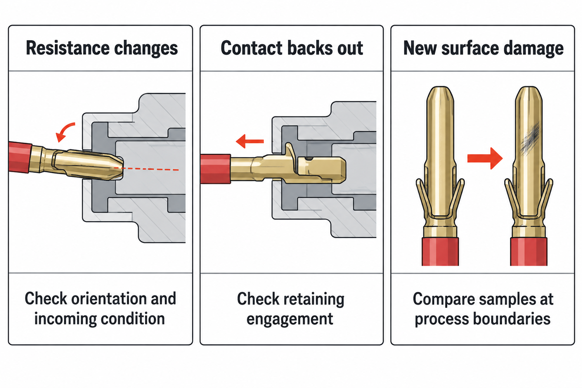
If insertion is unsuccessful, keep the part identity and condition as is prior to changing the recipe. A pin bending at entry, a socket damaged during transfer and a contact backing out after insertion call for different inspections. Increasing a setting without identifying the affected interface can mask the root cause.
What should be checked when insertion resistance changes?
Compare the contact orientation, incoming condition, housing cavity and preparation against the approved configuration. The Squba instructions specifically address orientation and unexpectedly high resistance for that system. Check the intended assembly before forcing the contact further. The instructions should be applied to the actual components in the system.
What if the contact looks seated but later backs out?
Review the retaining feature and the method used to establish engagement. Check if the observation just recorded contact presence, or established the required lock condition. Molex’s contact-retention guidance describes how lance engagement, housing condition and secondary retention affect terminal retention. Use the affected part specification to determine the test method and evaluate the result.
How can feeding damage be separated from insertion damage?
Inspect identified samples at agreed process boundaries. Compare contacts before and after presentation and completed assemblies. Use the same criteria to evaluate features at each boundary. This locates where a new mark or distortion first appears and gives the tooling discussion a specific target.
For twist-pins and insulators, the Twist-pin and Insulator Insertion Guide describes dedicated equipment context. Keep any conclusions from that process tied to its part construction and assembly sequence.
Decide what can be shared across connector variants
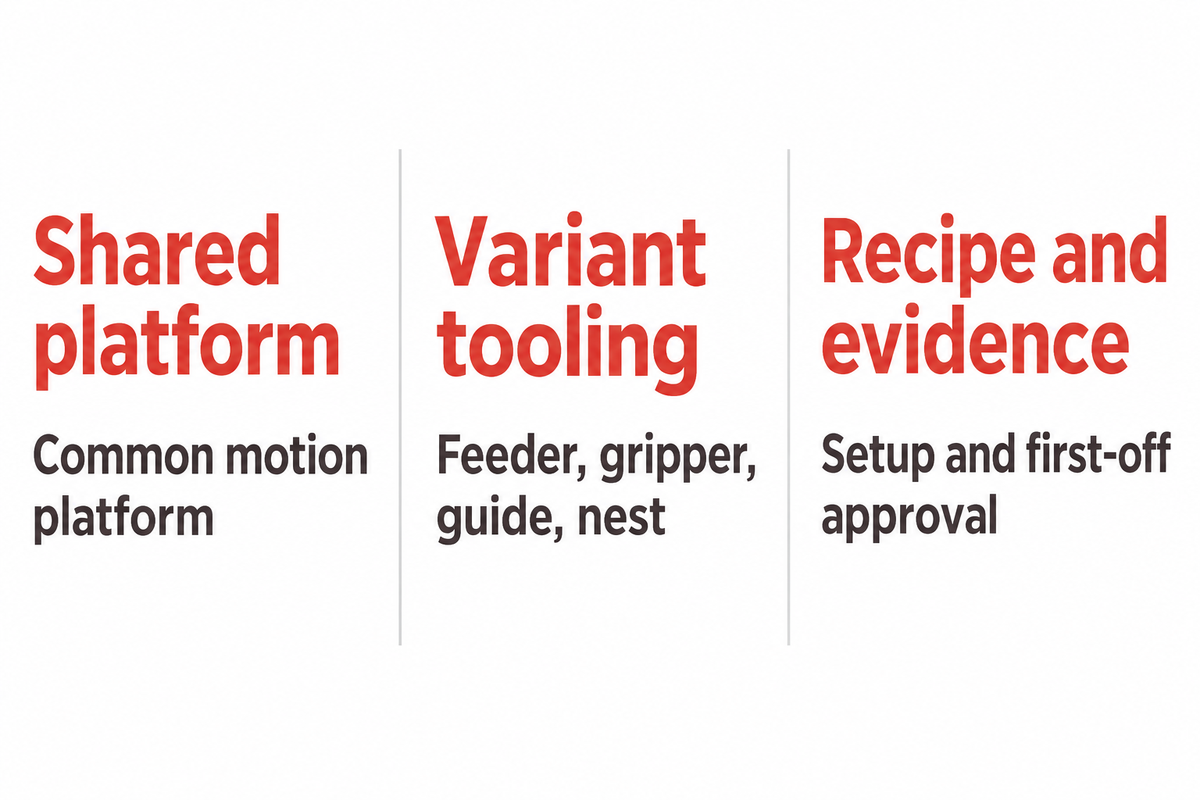
There should be a defined agreement on the compatibility of shared equipment. Consider the presentation of the contact, the features allowed during handling, the direction of insertion, the housing datum and method of acceptance for each proposed variant. Record what doesn’t change, what changes mechanically, and what changes in the recipe. This gives a family plan.
A supplier may offer a common motion platform while changing the feeder track, gripper, guide or nest. The quote should show the common motion platform and variant-specific features as separate items. For production, identify the change part and provide the setup sequence. Quality needs an approved first-off result for the selected configuration.
The more critical commercial question is how much of the quoted capability has been demonstrated with the intended parts. A lower initial quotation can leave additional fixtures, inspection work or trial activity outside scope. Compare complete scopes against the same contact families and sample plan before comparing price.
Molex’s application-tooling overview illustrates why tooling choice depends on the interconnect application and production needs. Use the broader automation-selection discussion in the existing pin insertion guide once the contact-to-housing requirements are clear.
Turn the interface review into a machine brief
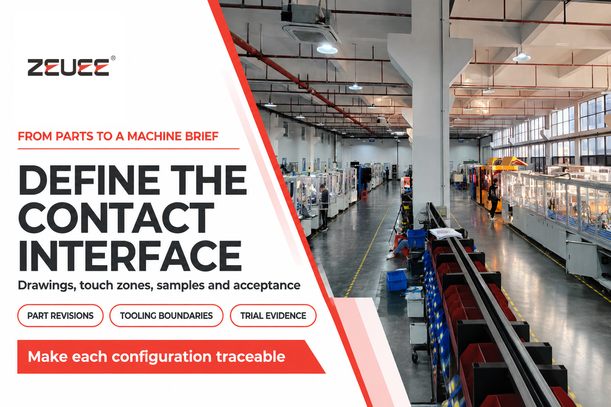
The objective is to provide sufficient information to an engineer to allow reconstruction of the intended assembly without guesswork. Attach the contact and housing drawings, their revisions, the input-and-output sketch, the evidence register and the sample plan. List the included variants and identify which ones need a demonstration.
- Parts and preparation. Identify pin and socket part numbers, housing cavities, plating, wire or crimp condition, seals and the condition in which they’re received.
- Tooling boundaries. Mark permitted touch zones, insertion direction, housing datums, support surfaces and the expected change parts.
- Acceptance evidence. Define the required seating, retention, condition and electrical checks with the applicable product documents.
- Production context. Specify demand, batch sizes, shift pattern, planned changeovers and the upstream and downstream interfaces.
- Handover. Agree sample returns, inspection records, recipe revisions, setup instructions and responsibility for unresolved trial findings.
Use the factory acceptance test checklist to manage the broader machine handover. Discuss device configuration with the supplier, using the ZEUEE pin and socket contact machine solution page. For a background to the company, see the ZEUEE company profile.
Discuss your contact and housing samples
FAQ
Can one machine assemble both pin and socket contacts?
Yes, when a shared motion platform is fitted with variant-specific tooling, such as a changed feeder track, gripper, guide or nest, that can handle each declared pin and socket part. Compare permitted tool contact, feed presentation, housing location, and the acceptance method for each case. Ask the supplier to identify shared hardware, change parts and recipe differences, then demonstrate the agreed configurations with traceable samples.
Does an insertion-force reading prove that the contact is retained?
Not by itself; depending on connector design and verified test method, force data can contribute to an assembly decision. Retention concerns the state of the retaining arrangement and the checks required. The acceptance plan should state what a force reading establishes and how the required retention condition is verified.
Why does socket handling need its own review?
The socket has a receiving opening and an internal contact structure with different permitted handling, depending on the design. Review where the tool touches, how the part is supported and how the opening is protected during transfer. Use the supplier’s contact drawing and assembly instructions to establish the acceptance criteria.
What is the most useful starting package for a quotation?
Provide the part numbers of the contact and housing, current drawings and representative samples, the incoming preparation, assembly orientation, and variants produced, and acceptance documentation. An annotated contact-to-cavity sketch helps the equipment supplier identify tooling assumptions and missing information before proposing a configuration.
Should every connector variant have a separate trial record?
Not necessarily, but each result must stay traced to the configuration that was tested. A shared machine recipe or similar part appearance does not by itself establish equivalent handling and retention behavior. Agree which variants the trial covers and document the engineering basis for any grouping, together with the corresponding tooling and inspection settings.
References & Sources
- Molex Connector Contact Retention Guide.
- Molex Squba application specification, document 2077760000-AS.
- Molex PowerWize application specification, document 2215971000-AS.
- Molex application tooling.
- TE Connectivity Pin Insertion and Press-Fit Machines for the printed-circuit-board equipment differentiation.
WHY WE WRITE THIS
About ZEUEE Engineering Insights
ZEUEE shares technical guides based on real automation project experience. Since 2005, we have designed and manufactured non-standard automation equipment for connector assembly, wire harness production, robotic lines, vision inspection, and smart factory upgrades.
Founded in 2005
20,000 m² production base
120+ specialists
150+ R&D patents
ISO9001:2015 certified