Get in touch with Zeyu lntelligent Industrial Company

Automatic Screw Feeding System: Blow Feeding, Vacuum Pickup, and Jam Validation Guide

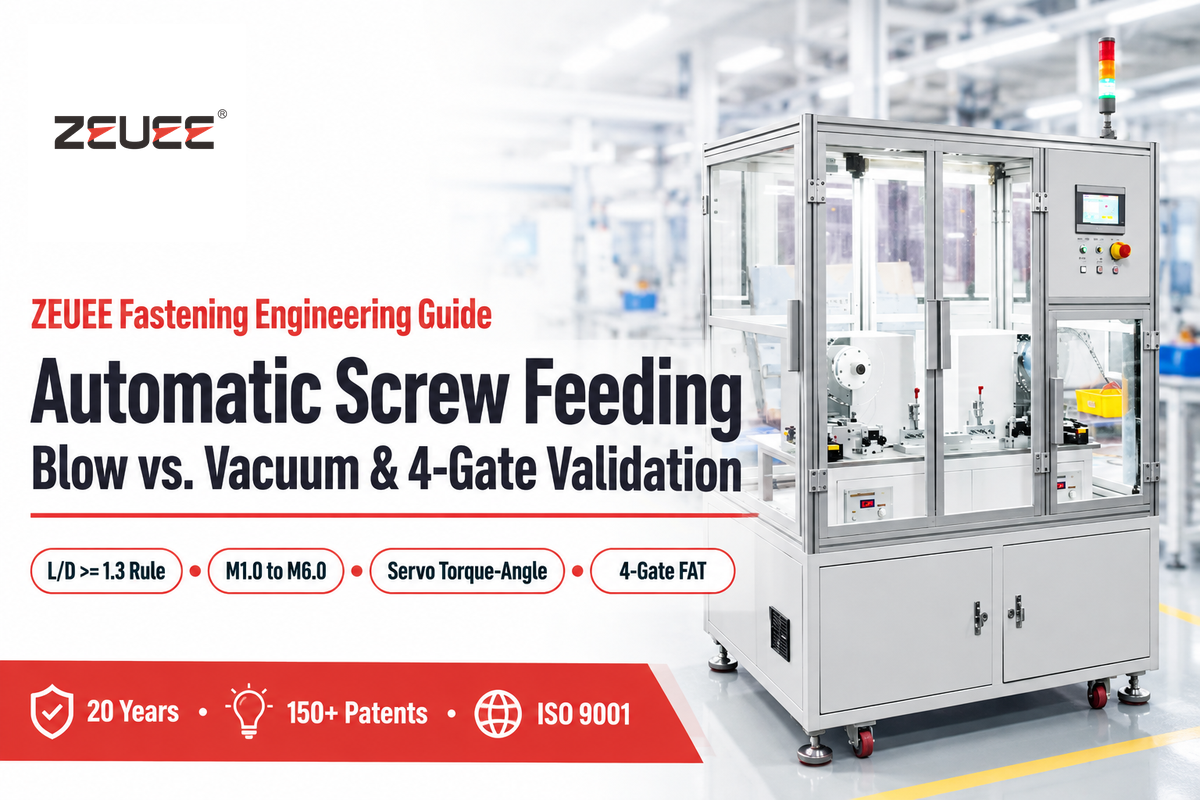
An automatic screw feeding unit consists of an industrial assembly unit that removes bulk fasteners from a hopper, orientates them on a rail, and delivers them to a screwdriver spindle. One delivery takes 1.2 to 2.2 seconds. Pneumatic blow feeding requires a screw length to head diameter ratio of at least 1.3.
Manually handling fasteners wastes 3.0 to 4.5 seconds per cycle as operators handle the fasteners by hand. Unintentional fastener jams caused by poor delivery architecture results in mid-hose jams, stripped plastic bosses, and scratched anodized housings. This document discusses mechanical singulation, blow-to-vacuum geometry, servo-torque angle control, and a four-gate validation methodology.
| Configuration Tier | Fastener Range | Delivery Method | Cycle Time per Screw | Typical Repeatability | Primary Industrial Application |
|---|---|---|---|---|---|
| Tier 1A: Benchtop Linear Brush Dispenser | M1.0 to M5.0 | Manual magnetic or vacuum bit pickup from rail | 2.5 to 3.8 s | Hand tool torque setting | High-mix electronics and manual assembly benches |
| Tier 1B: Benchtop Rotary Disc Presenter | M1.0 to M3.0 micro screws | Rotary turntable presentation to vacuum nozzle | 2.0 to 2.8 s | ±3% electric hand driver | Optical modules, wearables, and camera housings |
| Tier 2A: Handheld Pneumatic Blow-Feed Unit | M2.0 to M6.0 (L/D ≥ 1.3) | Pneumatic blow tube to split-jaw nosepiece | 1.3 to 2.0 s | ±5% to ±10% (clutch) | Appliance chassis, automotive trim, and sub-assemblies |
| Tier 2B: Handheld Torque-Arm Blow-Feed | M2.5 to M6.0 | Blow feed with carbon-fiber reaction arm | 1.4 to 2.1 s | ±3% current-control DC | Medium-torque industrial enclosures and switchgear |
| Tier 3A: Desktop Single-Spindle XYZ Machine | M1.2 to M5.0 | Blow feed or telescopic vacuum suction sleeve | 1.2 to 1.8 s | ±0.02 mm axis / ±2% torque | Printed circuit boards, smart meters, and 3C housings |
| Tier 3B: Desktop Dual-Y Shuttle XYZ Machine | M1.4 to M5.0 | Dual-table alternate loading with blow or suction | 1.0 to 1.5 s | ±0.02 mm axis / ±2% torque | Continuous two-fixture consumer electronics production |
| Tier 4A: Cobot Vacuum Fastening Cell | M1.6 to M5.0 (L/D < 1.3) | 6-axis collaborative robot with vacuum sleeve | 1.8 to 2.6 s | ±1.5% transducerized servo | Deep-well medical devices and anodized housings |
| Tier 4B: High-Speed SCARA Blow-Feed Cell | M2.0 to M6.0 / 20mm bolts | 4-axis SCARA robot with overlapped blow feed | 1.1 to 1.6 s | ±1.5% transducerized servo | In-line automotive modules and EV battery packs |
| Tier 4C: Multi-Spindle Synchronous Station | M2.5 to M8.0 | 2 to 8 parallel blow-feed spindles descending together | 2.0 to 2.8 s per 6 screws | ±1.5% multi-channel servo | Compressor covers, motor end-shields, and valve bodies |
How an Automatic Screw Feeding System Works: From Hopper Singulation to Bit Delivery
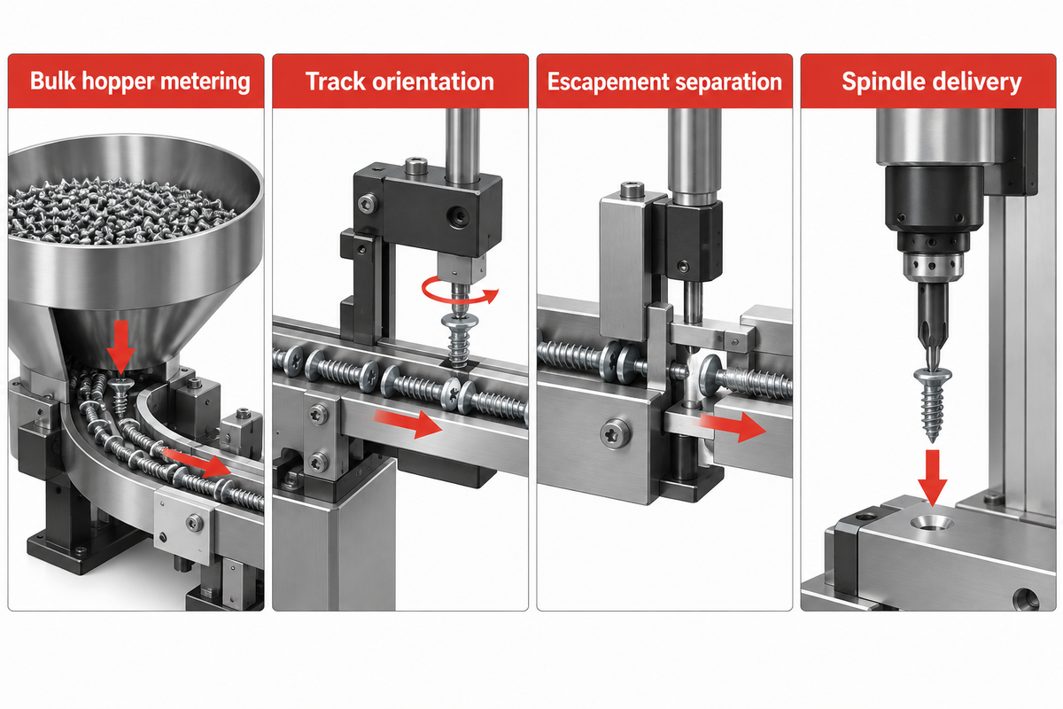
An automatic screw feeding system has a net cycle time of 1.25 to 1.80 seconds, per fastener, due to the pneumatic escapement recharging and robot travel time overlapping. There are four stages in the mechanical pipeline: hopper metering, screw orientation on the rail, escapement singulation, and transfer to the bit.
Early academic mechatronics design specifications, such as the Fall 2001 UC Berkeley ME102B StudMaster Fastening Project, illustrate automated dual-rail drill-and-drive positioning, stud detection, and programmable screw spacing. In industrial production feeders, every stage has to physically control the fastener center of gravity. If a fastener loses orientation during rail transit, the escapement jams before the spindle can cycle.
How Does the Four-Stage Pipeline Orient, Singulate, and Convey Screws to the Driver Bit?
The four stages in the process use gravity and vibration to align the screw shank down within a precision rail slot. A pneumatic cylinder shuttle then separates one fastener and uses either air or a vacuum to convey it to the bit. Fiber optic ring sensors validate mechanical hand offs within a 250 to 400 ms window.
- In stage one (bulk hopper metering), operators load 500 to 5,000 bulk fasteners into a stainless steel hopper or vibratory bowl reservoir. A proximity level switch controls the level of bulk fasteners to avoid stalling the primary rail.
- In stage two (track orientation) fasteners are enter the track onto parallel rails that support the underside of the screw head. The threaded shank is vertically aligned to the slot and a rotary brush is used to sweep away accumulated parts.
- In stage 3 (escapement separation), a pneumatic cylinder shuttle or a rotary disc at the track outlet, separate one fastener from a queued column. This escapement isolates the leading screw at the discharge port while blocking the trailing queue.
- In stage four (spindle delivery) a pulse of compressed air, or a pick-and-place robot, is used to convey the screw to the Chuck jaws.
When integrating custom automated assembly machines, overlapping stage 4 with axis motion is the primary way to cut takt time. The table shows approximate millisecond timing budgets between overlapped blow feeding and sequential vacuum pickups.
| Process Phase | Overlapped Blow-Feed System (ms) | Sequential Vacuum Pick-and-Place (ms) | Timing Optimization Mechanism |
|---|---|---|---|
| Escapement Singulation & Release | 120 to 180 ms (overlapped) | 150 to 200 ms (in-nest) | Triggered during prior screw final seating |
| Tube Transit / Pick Travel | 150 to 250 ms (overlapped) | 400 to 650 ms (X-Y-Z travel to nest) | Blow transit occurs while robot moves to next hole |
| Ring Sensor Transit Verification | 50 to 100 ms (overlapped) | 50 to 100 ms (vacuum switch check) | Fiber-optic ring sensor confirms screw arrival at chuck |
| Z-Axis Approach & Thread Finding | 250 to 350 ms | 300 to 400 ms | Soft-start reverse 30° to align first thread |
| High-Speed Rundown & Final Torque | 500 to 800 ms | 600 to 900 ms | Two-step servo speed profile to target torque |
| Z-Axis Retract & Dwell | 130 to 180 ms | 500 to 720 ms (return to feeder nest) | Blow-feed nozzle stays at the workpiece plane |
| PLC OK Handshake & Curve Log | 50 to 70 ms | 100 to 130 ms | Fieldbus torque-angle status output to cell controller |
| Total Net Cycle Time per Screw | 1,250 to 1,800 ms (1.25 to 1.80 s) | 2,100 to 3,100 ms (2.10 to 3.10 s) | Blow feeding saves 0.85 to 1.30 s per screw |
Vibratory Bowl Feeder vs. Step Feeder and Screw Dispenser Mechanisms
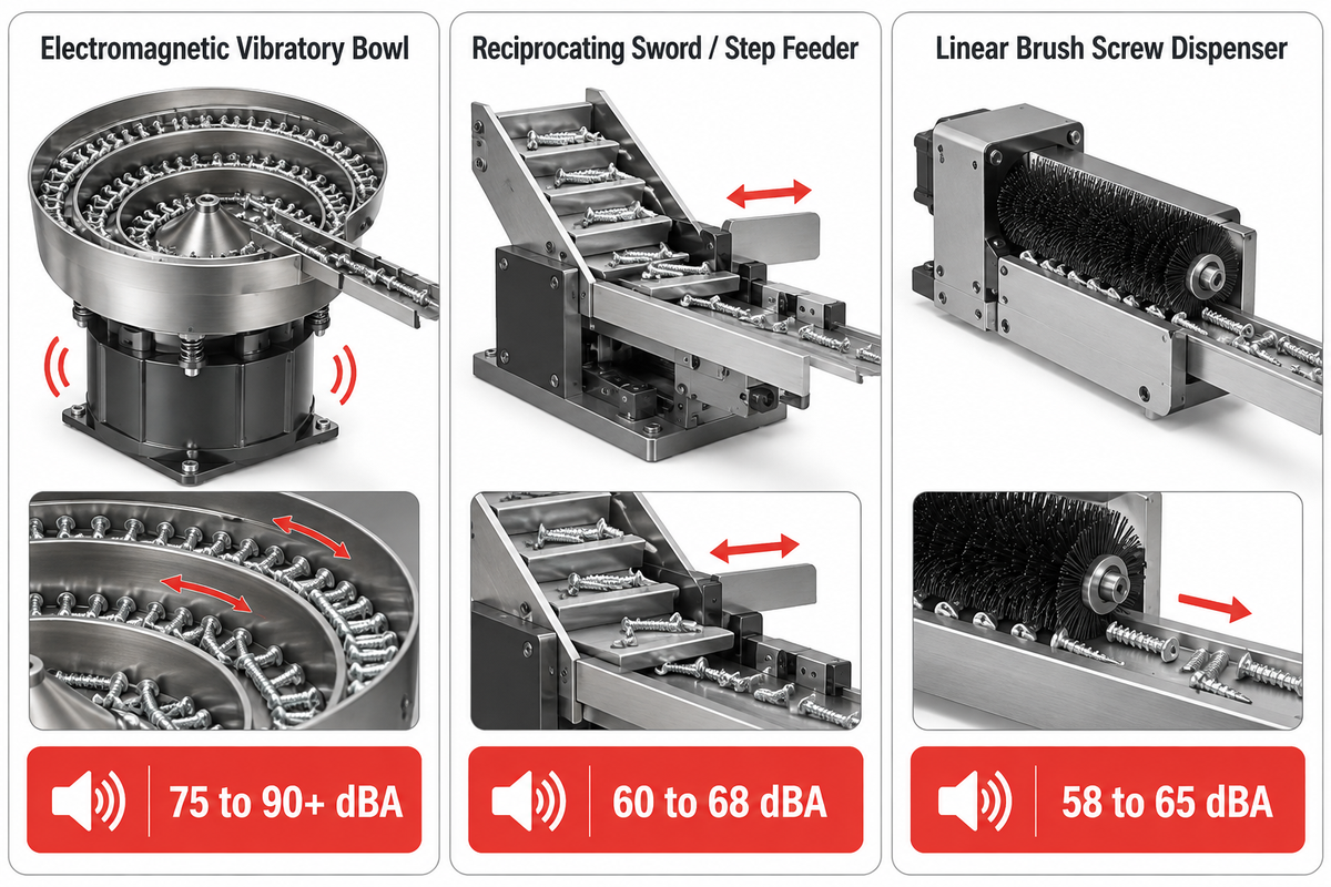
For less noise and coating protection, consider a polyurethane-lined reciprocating step feeder: Expect a sound level of 60 to 68 dBA with minimal fastener recirculation wear. Alternatively, use an unlined vibratory feeder bowl. Expect a sound level of 75 to 90+ dBA, especially if the fasteners are metal. Unlined vibratory feeder bowls run at 75 to 90+ dBA in metal fastener service; a linear screw arranging machine is another option.
Conventional electromagnetic vibratory bowls use a coil to throw bulk hardware in a rising helix at 60 to 120 Hz. Orientation mechanisms, such as US Patent US6986440B2 (Escapement System), use a rotating drum, locator assembly, probe, and a proximity sensor to detect the position of the fastener, and release it at the end of the rotation. Along the bowl rail itself, angled wiper blades reject screws that don’t enter track in a vertical position. Vibratory bowls are capable of handling high feed rates of up to 60 parts per minute. Prolonged recirculation, however, can wear off the zinc flake or black oxide coating.
When Should You Specify a Step Feeder Instead of a Vibratory Bowl Feeder for Coated Fasteners?
In low-noise workstations or cleanrooms with a noise level below 68 dBA, you can specify a step feeder instead of a vibratory bowl to lift fasteners. Step feeders employ reciprocating plates. Vibratory bowls use continuous recirculation. The mechanical action of reciprocating plates cuts coating abrasion dust by more than 80 percent.
For manual benches and light cobot cells, a compact screw dispenser with an arranging machine conveyor sweeps miniature screws onto a central linear rail. These benchtop units use a motorized nylon brush drum to clear excess hardware without high-amplitude vibration. A rotary brush drum holds less bulk volume, between 150 and 400 ml, compared to an industrial step feeder.
| Engineering Parameter | Electromagnetic Vibratory Bowl | Reciprocating Sword / Step Feeder | Linear Brush Screw Dispenser |
|---|---|---|---|
| Operating Acoustic Noise | 75 to 90+ dBA (unlined); 68 to 74 dBA (enclosed) | 60 to 68 dBA | 58 to 65 dBA |
| Coating Abrasion & Particle Shedding | Moderate to High (continuous recirculation) | Very Low (gentle upward plate indexing) | Low (nylon brush sweep on linear track) |
| Maximum Output Rate | 40 to 65 screws/min | 30 to 45 screws/min | 20 to 35 screws/min |
| Applicable Fastener Range | M1.6 to M8.0 (up to 35 mm length) | M2.5 to M8.0 (up to 45 mm length) | M1.0 to M5.0 (micro & standard screws) |
| Suitability for Oily / Waxed Screws | Poor (stiction stalls helical climb) | Good (positive mechanical plate lift) | Moderate (brush bristles require periodic cleaning) |
Blow Feeding vs. Vacuum Pickup: The L/D Ratio and Recess Geometry Boundary
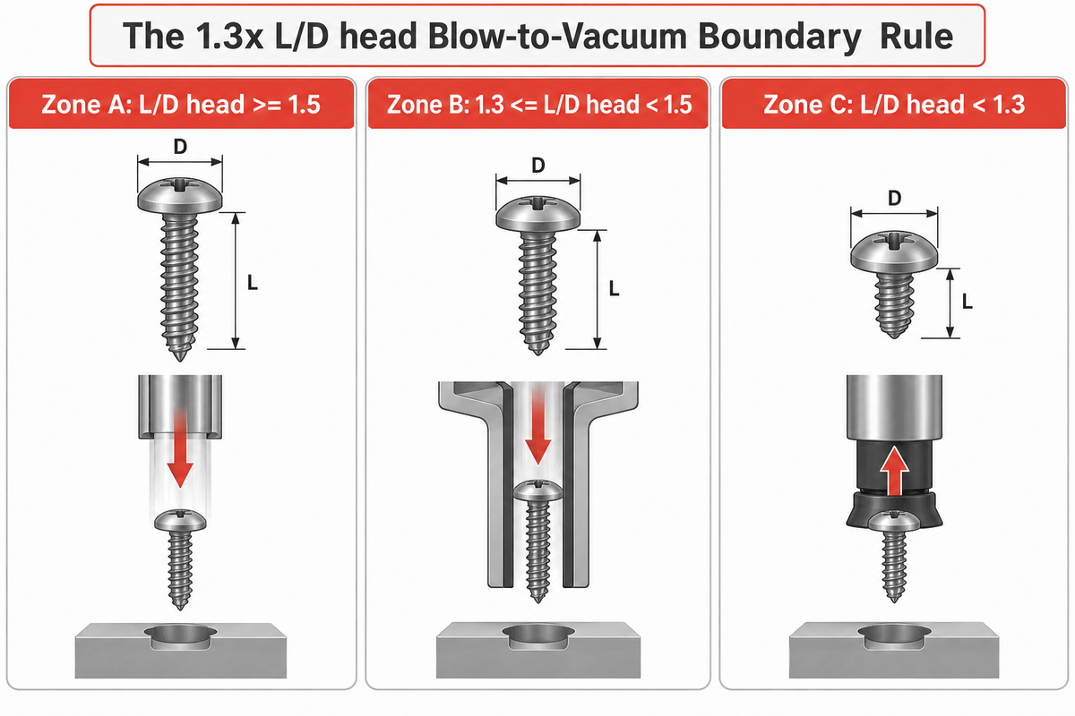
The boundary between pneumatic blow feeding and vacuum pickup is determined by the L/D ratio of the screw head and sidewall clearance. For blow feeding, the L/D ratio of the screw head should be 1.3 or greater, and at least 2.5 mm radial jaw clearance is required. Screws with an L/D ratio of less than 1.3 require vacuum pickup.
Engineers can accidentally use the major thread diameter when calculating this ratio instead of the head diameter. An M3 pan-head screw that’s 4.0 mm long has a length-to-thread ratio of 1.33. However, its pan head diameter is 5.6 mm, yielding a true L/D head of 4.0 ÷ 5.6 = 0.71. Shooting that short fastener through a blow tube causes aerodynamic drag to flip it 90 degrees and jam the hose bend.
How Do Screw Length-to-Head-Diameter Ratio and Sidewall Clearance Dictate Blow vs. Vacuum Delivery?
A fastener with L/D head ≥ 1.5 travels stably in a round blow tube, while ratios between 1.3 and 1.5 require profiled tubing, and ratios below 1.3 mandate vacuum pickup. Recessed bosses that are ≥ 15 mm deep with ≤ 2.5 mm side wall relief, require the same.
Many advanced high-speed feeding designs, including Utility Patent CN224226109U for Fast Screw Feeding Devices, use sorting blocks and/or profiled channels to stabilize fasteners during pneumatic transport. We define The 1.3x L/Dhead Blow-to-Vacuum Boundary Rule across three operating zones:
- Zone A (L/Dhead ≥ 1.5 – Standard Pneumatic Blow Feeding) The shank length is at least 1.5 times the diameter of the head. Blow feeding can reliably deliver 35 to 60 screws per minute with split-jaw nosepieces.
- Zone B (1.3 ≤ L/Dhead < 1.5 – Marginal Profiled-Tube Zone): The shank is only slightly longer than the head width. Standard round tubes allow occasional 45-degree cocking at tight bends. Reliable feeding in Zone B requires T-profiled anti-tumble hoses, zero-backlash escapements, and bend radii greater than 200 mm.
- Zone C (L/Dhead < 1.3 – Mandatory Vacuum or Mechanical Pick-and-Place): Short screws, pancake heads, and wide truss heads have a shank length of less than 1.3 times the head diameter. Blow tubes aren’t acceptable for Zone C. The spindle must use a telescopic vacuum suction nozzle or a magnetic pick-up.
| Fastener & Housing Condition | Zone A: L/Dhead ≥ 1.5 | Zone B: 1.3 ≤ L/Dhead < 1.5 | Zone C: L/Dhead < 1.3 |
|---|---|---|---|
| Open Flat Surface (≥ 3.0 mm Radial Clearance) | Recommended: Standard Pneumatic Blow Feed | Suitable: Profiled-Tube Blow Feed | Recommended: Vacuum Suction Pickup |
| Shallow Counterbore (< 10 mm Deep, ≥ 2.5 mm Clearance) | Recommended: Long-Stroke Split-Jaw Blow Feed | Suitable: Sliding-Head Blow Nosepiece | Recommended: Telescopic Vacuum Sleeve |
| Deep Recessed Well (15 to 80 mm Deep, < 2.0 mm Clearance) | Recommended: Thin-Wall Vacuum Sleeve (0.8 mm wall) | Recommended: Thin-Wall Vacuum Sleeve | Recommended: Thin-Wall Vacuum Sleeve |
| Class-A Cosmetic / Anodized Surface (Zero Chip Rule) | Recommended: Vacuum Pickup (avoids blow-by particles) | Recommended: Vacuum Pickup | Recommended: Vacuum Pickup |
Fastener Geometry Rules: Feeding M1, M6, Short Screws, and System for Set Screws
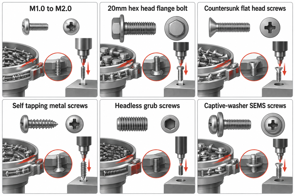
The style of the fastener head, type of thread tip, and washer assembly determine the width of the track slot and stroke of the escapement across each screw size from M1.0 to M6.0. A universal track works for standard pan-head screws. On the other hand, flat head countersunk screws and hex flange bolts require specialized orientation tooling.
When engineers specify equipment for 3C electronics assembly automation, miniature screws in the M1.0 to M5.0 range are prevalent in the bill-of-materials. Structural brackets and automotive castings require M6 fasteners or a 20mm hex head flange bolt. US Patent Application US20140238818A1 (Centrifugal Bowl Parts Feeder System with Segmented Tooling Sections) uses replaceable segmented tooling sections with locating connections and part ID to adapt a single tooling base to various fastener profiles.
- Screws in the M1.0 to M2.0 range weigh less than 0.05g, and machining oils or static charges cause them to stick to the rails of vibro-feeders. Therefore, manufacturers maintain hold rail clearance at +0.10 to +0.15 mm of the major diameter of the thread.
- Heavy M5, M6 and 3/8-16 x 20mm hex head flange bolts have large heads and wide flanges. Standard feeders can’t push them up vertical hoses. Using hardened steel step feeders with high thrust pneumatic escapements and 10 to 16 mm inner diameter delivery hoses is required.
- Countersunk flat head screws have an 82 degree or 90 degree conical underside that causes adjacent fasteners to ride up and overlap on flat feeder rails. Tracks require a top confinement cover plate with a vertical clearance of less than 0.3 mm to avoid shingling.
- Self tapping metal screws can snag on the walls of soft polyurethane tube during transport. Use a more stiff nylon-12 or PTFE-lined tubes, and increase the bend radius to 250 mm.
- Headless grub screws can’t hang down from a standard slot, and a system for set screws uses a through-beam fiber optic sensor to tell which end contains the hex drive socket. A pneumatic turnover wheel then flips inverted screws, prior to blow delivery.
- Captive-washer SEMS screws employ free-spinning flat or split lock washers that must fit flat against the screw head prior to entering the escapement. Track drop-offs and vibratory amplitude can cause washers to tilt and become wedged in the shuttle block.
Pneumatic Blow-Feed Tube Routing, Air Consumption, and Escapement Design
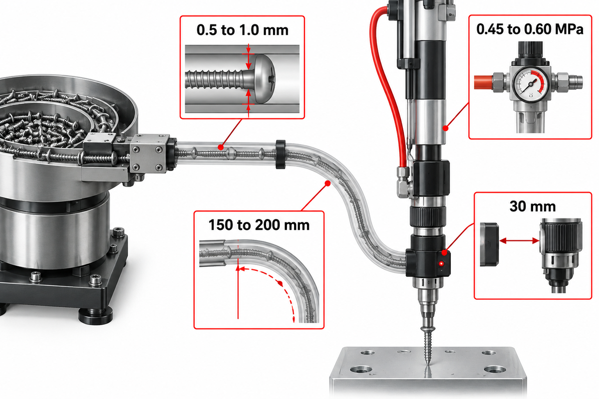
A suitable automatic screw feeder system matches the diameter of the delivery tube to that of the screw head within the range of 0.5 to 1.0 mm. Bending hoses with a minimum bend radius of 150 to 200 mm prevents mid-flight wedging. Dry, oil free compressed air at 0.45 to 0.60 MPa keeps escapement valves clean and free of deposits.
Each pneumatic blow-feed cycle uses 1.5 to 3.5 normal liters of free air per screw. Standard distances for delivery are 1.5 to 3.0 meters for bench-top and robotic-cell applications. Horizontal runs greater than 5.0 meters are impractical. Beyond 5.0 meters, the time between cycles increases to more than 450 milliseconds.
Isolation of pneumatic energy is mandatory during maintenance and jam removal. Industrial robot safety standards, specifically ISO 10218-1:2025 Robotics Safety Requirements Part 1 for industrial robots and ISO 10218-2:2025 for robot systems, applications, and cell integration, establish updated 2025 safety and functional safety requirements for industrial robots and integrated robot cells. Integrators are required to install pneumatic dump valves to deliberately depressurize the stored air in the blow manifold and actuators before the operators open the interlocked guard door.
- The inner diameter of the delivery hose should be sized to: IDtube = Dhead + 0.5 to 1.0 mm. If clearance is under 0.4 mm, head burrs wedge inside curves, whereas clearance above 1.5 mm lets shorter fasteners tilt and jam. Clearance greater than 1.5 mm allows the fastener to push against the delivery hose, and jam it.
- The radius of curvature of feed tubes should be a minimum of 150 mm for M2-M3 screws and 200 to 250 mm for M4-M6 fasteners. Never zip-tie a blow tube tightly to a sharp robot wrist joint.
- Set the duration of the blow pulse between 150 to 300 ms. A ring proximity sensor, placed 30 mm from the driver chuck, senses arrival of a fastener and automatically closes the air valve to save compressed air.
Engineering Warning, Never Use Oiled Air Lubricators on Blow-Feed Lines: Plant maintenance teams sometimes install standard FRL (Filter-Regulator-Lubricator) units upstream of a screw feeder. Oil mist coats the inside of the polyurethane blow tube and vibratory track. Within 48 hours of production, metal dust and fastener wax mix with the oil film to form a sticky paste. That paste causes chronic mid-tube jamming. Always specify ISO 8573-1 Class 1.4.1 dry, oil-free compressed air with a 5-micron coalescing filter.
Vacuum Pickup Screw Driving and Telescopic Nozzle Clearance for Deep Wells
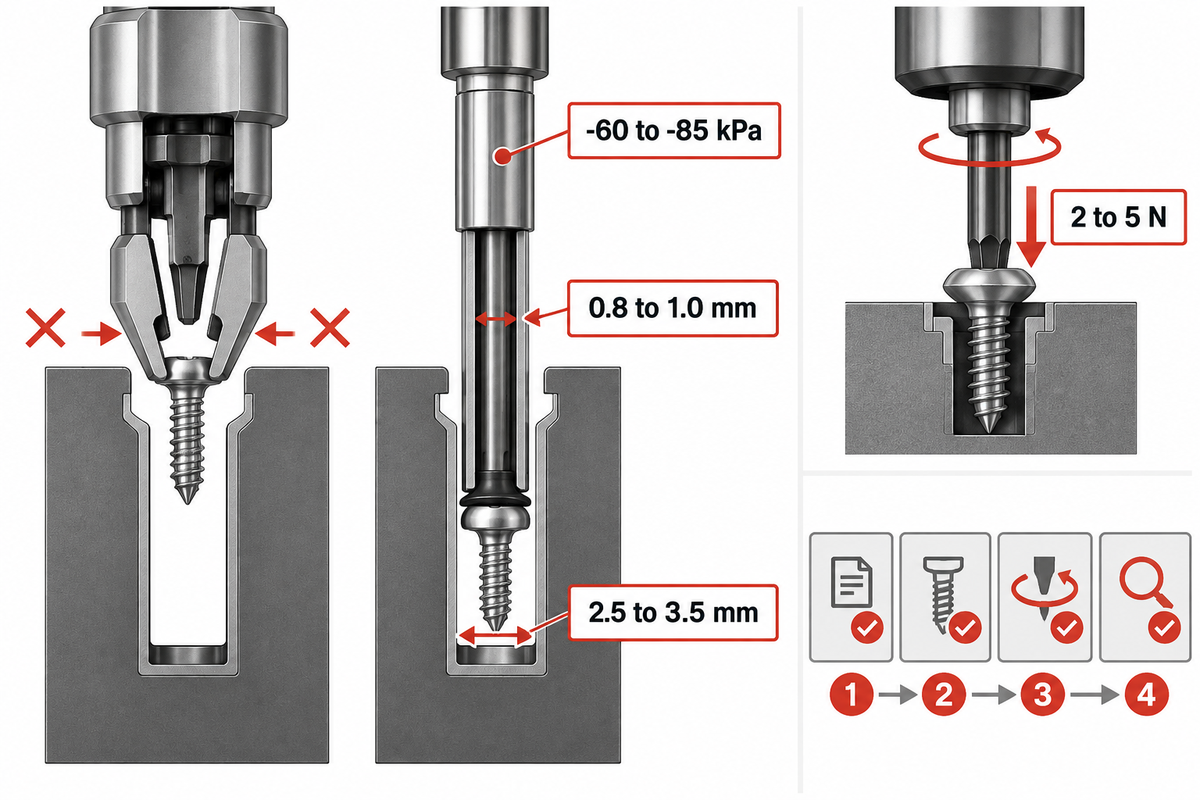
Vacuum pickup screw driving uses a spring-loaded telescopic suction sleeve around the driver bit to hold non-magnetic or low-L/D fasteners at -60 to -85 kPa. Thin-walled vacuum tubes require only 0.8 to 1.0 mm of radial clearance. They easily reach inside deep recessed wells where split-jaw blow chucks can’t fit.
A vacuum suction nozzle provides an excellent solution for two problems. First, magnetic driver bits don’t work with austenitic stainless steel (A2-70 or A4-80), aluminum, brass, or titanium hardware. Second, the attraction of iron filings by the magnet on the bit can foul electronic circuit boards. A vacuum suction nozzle can pneumatically grip the screw head.
For rotary assembly tools, performance testing under ISO 5393:2017 Rotary Tools for Threaded Fasteners defines laboratory procedures for evaluating torque repeatability and the precision of built-in torque measurement systems across continuous-torque tools from 0.5 Nm to 2,000 Nm. When pairing a precision electric spindle with a vacuum sleeve, concentric alignment between the bit tip and suction nozzle determines pick reliability:
- A Venturi vacuum ejector or rotary vane pump keeps a vacuum of -60 to -85 kPa (-18 to -25 inHg) in the nozzle chamber. A digital vacuum pressure switch verifies that the screw forms an air-tight seal with the nozzle tip before Z-axis travel is initiated.
- During pickup at the presentation pocket, the rotating driver bit engages the Torx, Phillips, or hex recess under a 2 to 5 N spring preload while vacuum locks the head against the sleeve face.
- Standard split-jaw blow chucks have an outward expansion as the bit passes through and require 2.5 to 3.5 mm of radial clearance around the screw head. A rigid vacuum sleeve made of stainless steel requires 0.8 to 1.0 mm of radial clearance and is compatible with recessed bosses of up to 80 mm.
Servo Screwdriver Torque-Angle Control vs. Pneumatic Clutch Drivers
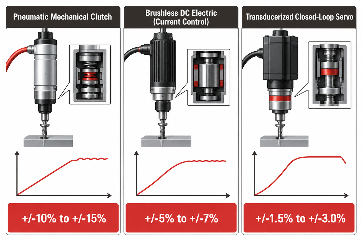
Closed-loop servo electric screwdrivers hold torque repeatability within ±1.5% to ±3.0% and monitor rotational angle in degrees. Mechanical-clutch pneumatic screwdrivers hold a wider ±10% to ±15% torque band. Combining torque, angle, and screw counting eliminates unseated fasteners and missing hardware on critical assemblies.
Industrial fastening guidelines such as VDI/VDE 2862 Blatt 1 and Blatt 2 classify bolted joints into Risk Categories A, B, and C based on failure consequences. Category A joints (high risk) and Category B joints (function critical) require control and monitoring of all key input variables to be continuous. Laboratory tool capability across 0.5 Nm to 2,000 Nm is tested under ISO 5393:2017 Performance Test Methods, which was last reviewed and confirmed by ISO in 2023 and replaced the withdrawn ISO 5393:1994 edition. Micro-fasteners below 0.5 Nm require documented modified test procedures.
Why Does Torque-Only Monitoring Fail to Catch Floating Screws and Cross-Threading?
Torque-only monitoring fails because a cross-threaded screw or burred blind hole hits target shut-off torque early while the head sits 1.5 to 3.0 mm above the part surface. Monitoring the rotational rundown angle immediately catches this defect.
When creating automotive component fastening systems, engineers replaced mechanical clutch tools with programmable brushless DC or transducerized servo spindles. The control system executes a multi-step fastening specification and integrates a batch counting machine function. Fixture clamps remain locked until the precise screw count per assembly is verified.
| Spindle Specification | Pneumatic Mechanical Clutch | Brushless DC Electric (Current Control) | Transducerized Closed-Loop Servo |
|---|---|---|---|
| Torque Repeatability (±3σ) | ±10% to ±15% | ±5% to ±7% | ±1.5% to ±3.0% |
| VDI/VDE 2862 Joint Category Fit | Category C (Non-critical joints) | Category B / C (Standard production) | Category A & B (Safety & function critical) |
| Floating Screw / Cross-Thread Detection | None (mechanical spring trip only) | Basic angle window + batch screw counting | Full torque-angle trace + gradient monitoring |
| Programmable Parameter Sets | 1 (manual spring collar adjustment) | 8 to 16 digital parameter sets | 50 to 250+ networked recipes via PLC |
| Data Traceability & SPC Logging | No native digital output | OK / NG discrete I/O + cycle count | Full curve storage per serial barcode (MES/QMS) |
Preventing Screw Jams and Floating Screws: A 4-Gate Factory Validation Protocol
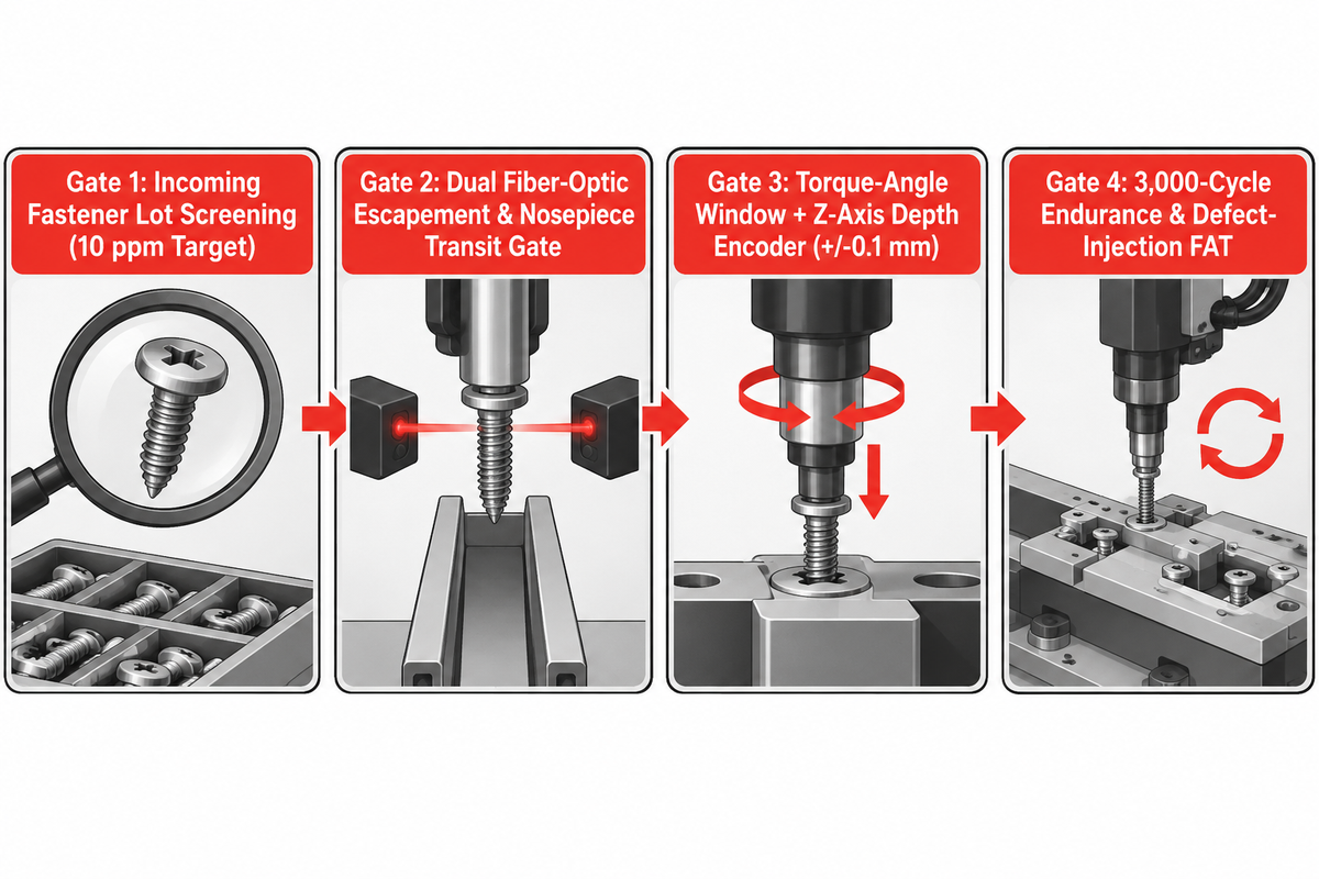
Preventing feeder jams and floating screws requires 10 ppm incoming fastener quality with dual transit sensors, Z-axis seating encoders and a 3,000-cycle Factory Acceptance Test (FAT). We call this The 4-Gate Fastener & Joint Validation Protocol. We codify this as The 4-Gate Fastener & Joint Validation Protocol , which stops malformed hardware at the hopper and blocks unseated screws from passing downstream.
A counterintuitive passage in DEPRAG’s engineering manual, Guideline Screw Feeding states that a commercial fastener lot wherein up to 3% bad parts are allowed isn’t always sufficient for automated feeding. At 30 screws per minute, a 1% bad part rate causes one jam every 3.3 minutes. DEPRAG stipulates that to ensure production efficiency, an incoming fastener quality of 10 ppm (1 bad part per 100,000 screws) is required via optical sorting.
What Factory Acceptance Testing Protocol Verifies Zero-Jam Feeding Before Shipment?
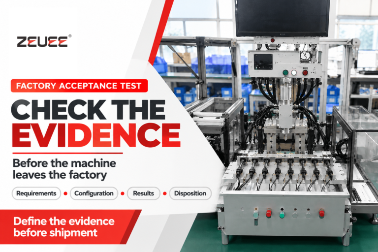
A Factory Acceptance Test (FAT) simulates machine use at a customer site. A rigorous Factory Acceptance Test runs 3,000 continuous fastening cycles using production fasteners from at least two supplier lots, requiring a feeder jam rate below 300 ppm. The test applies a feeder jam rate of 300 parts per million (ppm) or less. The FAT requires 100% automatic lockout on cross-thread, stripped-boss, and wrong-length defect samples.
Engineers must distinguish incoming fastener lot quality from machine run-off testing. The 10 ppm figure is the optical-sorted fastener cleanliness target, whereas the 3,000-cycle FAT validates short-term mechanical feeder stability before shipment. While VDI/VDE 2862 mandates torque and angle monitoring in a solution-neutral manner, custom integrators such as ZEUEE add a ±0.1 mm linear Z-axis stroke sensor to detect floating screws when blind-hole depth varies. Cell safety interlocks during FAT run-off must also comply with ISO 10218-2:2025 Robot Systems and Integration Safety.
Gate 1: Incoming Fastener Lot Screening (10 ppm Target)
Incoming lots of fasteners are inspected by quality technicians using go/no-go ring gauges to check for head burrs, bent shanks, missing recesses, and plating buildup.
Gate 2: Dual Fiber-Optic Escapement & Nosepiece Transit Gate
Install a high-speed fiber-optic ring sensor in Sensor A at the escapement discharge port. Place Sensor B above the spindle chuck. If a screw leaves Sensor A but misses Sensor B within 400 ms, the PLC halts the cycle to block a double-feed.
Gate 3: Torque-Angle Window + Z-Axis Depth Encoder (±0.1 mm)
Combine servo spindle torque angle windowing with a linear Z-axis stroke encoder (repeatability of ±0.1 mm). Any fastener that reaches the set target torque before it reaches the programmed Z-axis seating plane (±0.25 mm) is discarded as a floating screw.
Gate 4: 3,000-Cycle Endurance & Defect-Injection FAT
Perform 3,000 continuous cycles of turnkey automated assembly line integration. Introduce 10 deliberate defects (3 short screws, 3 unthreaded blanks, 2 stripped bosses, and 2 double hits) and confirm 10/10 automatic NG lockouts.
Cost Effective Automatic Screw Feeder Pricing, ROI Payback, and System Tiers
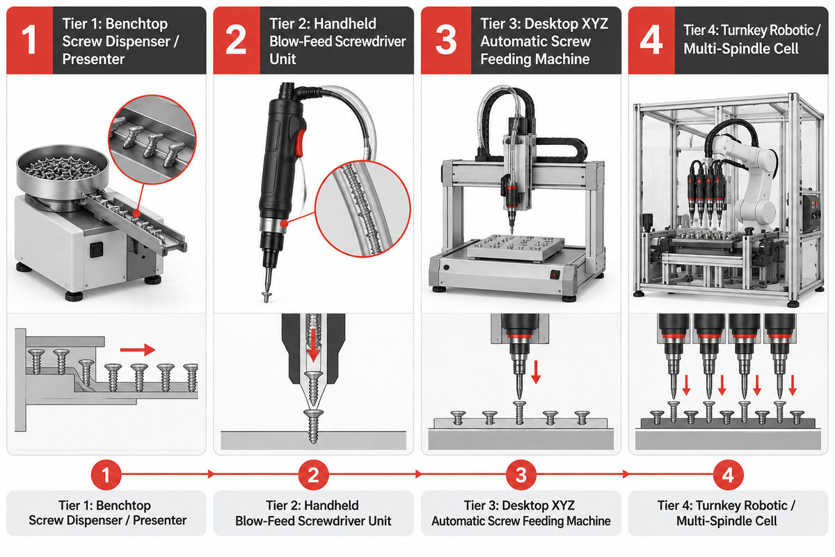
A cost effective automatic screw feeding system ranges from $250 to $1,800 for a benchtop screw dispenser up to $22,000 to $85,000+ for a turnkey robotic cell. Replacing manual screw driving cuts cycle time from 4.8 seconds to 1.6 seconds per fastener. Most plants achieve full capital payback in 4.5 to 8.5 months.
According to DEPRAG’s Guideline Screw Feeding economic benchmarks, specifying a dual-track twin feeder for two adjacent spindles saves approximately 25% compared to buying two single feeding machines. Upgrading to an automatic screw feeding machine boosts line productivity and supports efficient production across multi-shift schedules. Standardized tool verification under ISO 17104 Rotary Tool Standards helps buyers benchmark spindle durability before capital approval.
How Much Does an Automatic Screw Feeding System Cost Across Benchtop, Handheld, and Robotic Tiers?
An automatic screw feeding system costs $250 to $1,800 for a benchtop presenter and $1,800 to $6,500 for a handheld blow-feed unit. Desktop XYZ automatic screw feeder machines run $4,500 to $16,000, while turnkey robotic screwdriving cells cost $22,000 to $85,000+.
| System Tier | Equipment Price Range (USD) | Typical Labor Reduction | Throughput (Screws / Hour) | Typical ROI Payback Period |
|---|---|---|---|---|
| Tier 1: Benchtop Screw Dispenser / Presenter | $250 to $1,800 | Saves 1.0 to 1.5 s/screw (manual pick) | 900 to 1,200 screws/hr | 1.5 to 3.0 months |
| Tier 2: Handheld Blow-Feed Screwdriver Unit | $1,800 to $6,500 | Saves 2.2 to 3.0 s/screw (one-hand drive) | 1,500 to 2,200 screws/hr | 3.0 to 5.5 months |
| Tier 3: Desktop XYZ Automatic Screw Feeding Machine | $4,500 to $16,000 | 1 operator tends 2 to 3 desktop units | 1,800 to 2,600 screws/hr | 4.5 to 7.5 months |
| Tier 4: Turnkey Robotic / Multi-Spindle Cell | $22,000 to $85,000+ | 100% unmanned in-line fastening | 2,400 to 4,500+ screws/hr | 6.0 to 11.0 months |
Worked ROI Payback Example (Two-Shift Production Baseline): Consider an electronics housing assembly requiring 6 screws per unit across 2,500 units per day (15,000 screws/day). Manual pick-and-drive takes 4.8 seconds per screw (28.8 seconds per housing), requiring 20.0 operator hours daily. An automatic screw feeder machine cuts fastening time to 1.6 seconds per screw (9.6 seconds per housing). This upgrade reduces direct labor to 6.7 hours per day and cuts scrap from cross-threaded bosses by 1.8%. At a burdened labor rate of $18/hour over 250 working days, annual savings total $64,500. That pays back a $32,000 automated cell in 5.9 months.
Robotic Screw Feeder System Integration and Evaluating Custom Automation Builders
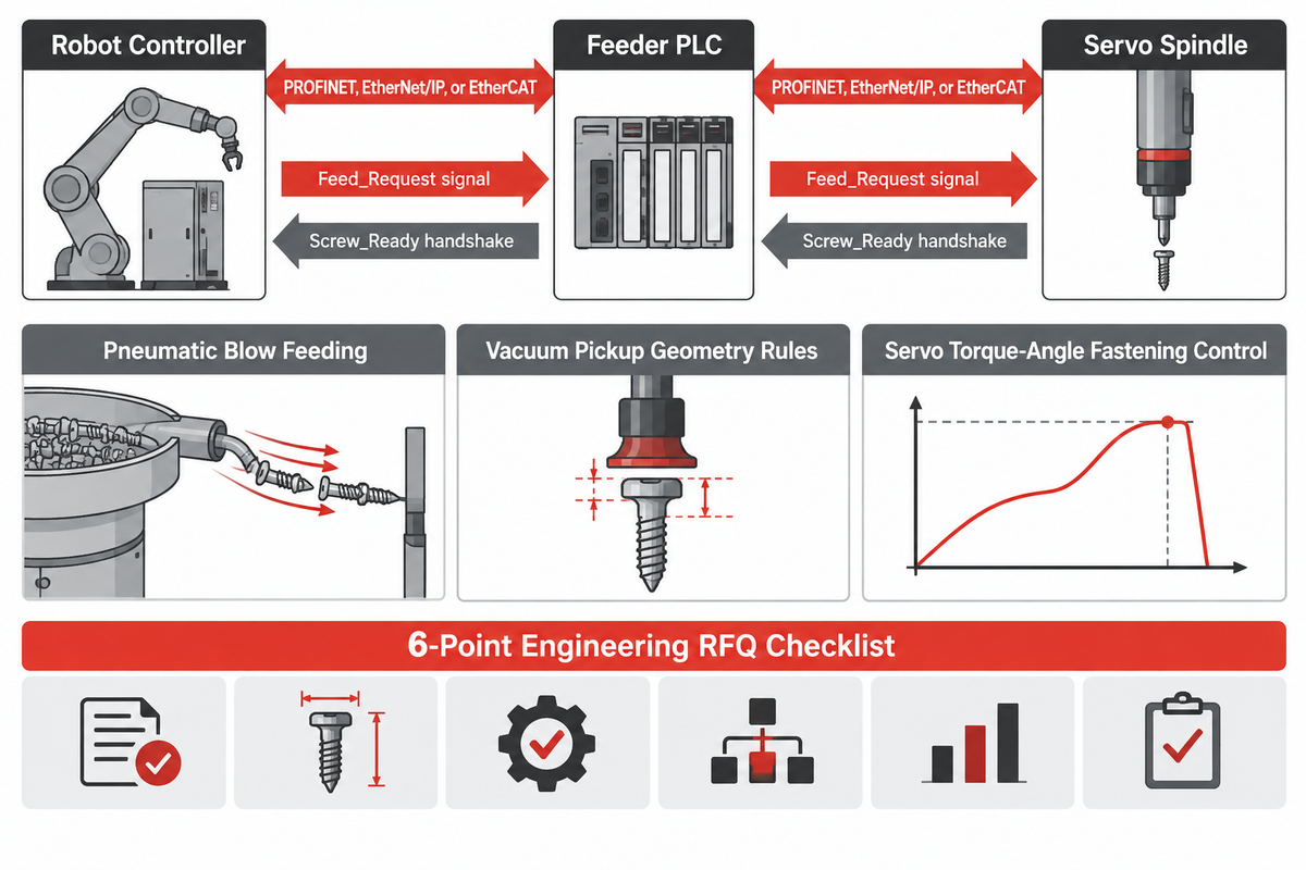
Integrating a robotic screw feeder system requires synchronizing 24V discrete I/O or fieldbus handshakes (PROFINET, EtherNet/IP, or EtherCAT) between the feeder PLC, robot controller, and servo spindle. Possible vendors include catalog feeder vendors and custom automation builders who provide a full fixture and conveyor cell.
In a robotic fastening station, the robot controller sends a Feed_Request signal as soon as the prior screw hits final torque. The feeder PLC actuates the escapement cylinder, verifies transit past the ring sensor, and returns a Screw_Ready handshake. All robot safeguarding, light curtains, and collaborative speed monitoring must conform to ISO 10218-2:2025 Industrial Robot Cell Integration.
How Do Catalog Screw Feeder Brands Compare With Custom Assembly Machine Integrators?
Standalone feeder bowls and spindles are offered by screw feeder brands (i.e. WEBER, DEPRAG, Desoutter, Visumatic, and Nitto Seiko). On the other hand, assembly machine integrators provide a complete turnkey solution (i.e. integrated vision, fixturing, rotary indexing tables, traceability, MES) for the assembly station.
When the focus is on reducing the overall costs of manufacturing, plants with in-house robotics teams purchase standalone feeder bowls (i.e. machine supplier). However, if the focus is on single-source supply of multiple products, plants order a complete turnkey automation solution.
- Standalone catalog feeder suppliers such as WEBER Screwdriving Systems, DEPRAG Schulz, Desoutter Industrial Tools, Visumatic, Nitto Seiko, Carlson Engineering and others supply standardized vibratory bowls, servo spindles and step feeders. These feeders are applicable to your projects if your plant has an internal robotics team to build the machine frame and safety enclosure, and to fixture the part to be fastened.
- Custom turnkey assembly builders such as ZEUEE (Shenzhen Zeyu Intelligent Industrial Science Technology Co., Ltd.) engineer complete automatic feeding stations to integrate assembly of electronic processing modules and related automotive components and assemble appliance housings. By integrating blow-feed and vacuum-pickup spindles with industrial robot integration cells and CCD vision alignment, a turnkey builder offers a factory-accepted machine from M1.0 micro-fasteners to M6 structural bolts.
6-Point Engineering RFQ Checklist Before Requesting a Feeder Quote
- To determine the L/Dhead ratio, provide a 2D drawing of a fastener to show thread diameter, total screw length, head diameter, type of drive recess (i.e. Torx, Phillips, etc.), and surface coating.
- Specify screw material as carbon steel, stainless steel (A2/A4), aluminum, or brass, and identify any captive washers and/or thread-locking patches.
- Share 3D STEP workpiece CAD files highlighting the deepest counterbore well and tightest sidewall clearance around every screw location.
- Define takt time for each screw (i.e. 1.5 seconds), total screws per housing, and volume for the day.
- Specify target torque in Nm, allowable tolerance (±2% servo vs. ±10% clutch), and MES curve storage rules.
- Prepare 1,000-3,000 production screws from the two lots for track tuning and 3,000 cycle Factory Acceptance Testing.
Ready to automate your fastening station? Contact our engineering team to request an automatic screw feeding system engineering evaluation to assess your 3D housing CAD and fastener specifications.
Frequently Asked Questions (FAQ)
Why does a pneumatic blow-feed unit jam when feeding oiled or waxed self-tapping fasteners?
Oiled or waxed self-tapping fasteners cause blow-feed units to jam because the film creates stiction along the tracks of the vibratory bowls. That film also traps airborne shop dust inside polyurethane delivery tubes. Within a few shifts, the oil and dust combine to create a gunk that slows screw speed and increases collisions. To reduce jamming, use a dry-tumbled fastener lot, use an antistatic PTFE-lined hose, or clean the feeder rails weekly.
Can a single adjustable-track screw dispenser handle multiple thread diameters on a high-mix line?
Yes, a benchtop screw dispenser with an adjustable track can feed multiple thread diameters from M1.0 to M5.0 after a 3 to 5 minute rail-width adjustment. Operators typically loosen the rail lock screws, set the track slot gap to match the new shank diameter and use a manual or vacuum pick up. A pneumatic blow-feed machine can’t feed multiple screw head diameters through one hose. Changing screw size on a blow-feed unit requires swapping the escapement shuttle, feed tube and nosepiece jaws.
How many production sample fasteners should you ship to a machine supplier for factory run-off testing?
Between 1,000 and 3,000 production fastener samples should be pulled from at least two separate manufacturing lots and shipped to your machine supplier prior to Factory Acceptance Testing (FAT). Production screws are used for the testing to accomplish the Tolerances for the Real World Head Thickness. A 3,000-cycle zero-jam test is run prior to shipment.
What compressed air specification is required for a blow-feed manifold?
A blow-feed manifold requires ISO 8573-1 Class 1.4.1 dry, oil-free compressed air regulated between 0.45 and 0.60 MPa (65 to 87 psi) with a 5-micron particulate filter and a refrigerative dryer. Never install an inline oil lubricator upstream of the feeder.
When should an assembly line use a multi-spindle head instead of a single-spindle robot arm?
An assembly line will require a fixed multi-spindle screw driving head when a product features 4 to 12 identical fasteners spaced 18 to 28 mm on a flat surface. Because all spindles descend simultaneously, a 6-spindle head drives six screws in 2.0 seconds total. A single-spindle SCARA robot needs 8.0 to 10.5 seconds to index sequentially across the same six holes. A single-spindle robot arm is the better choice when hole pitches are less than 18 mm, when screws are at various Z-heights, when there are frequent model changeovers, and when there are varied housing geometries.
References & Sources
- UC Berkeley Mechanical Engineering (ME102B, Fall 2001), StudMaster Dual-Rail Fastening Mechatronics Design Project Specifications, University of California, Berkeley.
- International Organization for Standardization, ISO 5393:2017, Rotary tools for threaded fasteners, Performance test method, Edition 3 (confirmed 2023).
- International Organization for Standardization, ISO 10218-1:2025, Robotics, Safety requirements, Part 1: Industrial robots, 2025 Revision.
- International Organization for Standardization, ISO 10218-2:2025, Robotics, Safety requirements, Part 2: Robot systems, robot applications and cell integration, 2025 Revision.
- International Organization for Standardization, ISO 17104, Rotary tools for threaded fasteners, Technical and safety specifications.
- United States Patent and Trademark Office / Google Patents, US6986440B2, Escapement System (Fastener Orientation and Delivery).
- United States Patent and Trademark Office / Google Patents, US20140238818A1, Centrifugal Bowl Parts Feeder System with Segmented Tooling Sections.
- China National Intellectual Property Administration / Google Patents, CN224226109U, Fast Screw Feeding Device for Automatic Screw Locking Machine.
WHY WE WRITE THIS
About ZEUEE Engineering Insights
ZEUEE shares technical guides based on real automation project experience. Since 2005, we have designed and manufactured non-standard automation equipment for connector assembly, wire harness production, robotic lines, vision inspection, and smart factory upgrades.
Founded in 2005
20,000 m² production base
120+ specialists
150+ R&D patents
ISO9001:2015 certified