Get in touch with Zeyu lntelligent Industrial Company

Flexible Feeder Selection: Changeover Economics and Bowl Limits

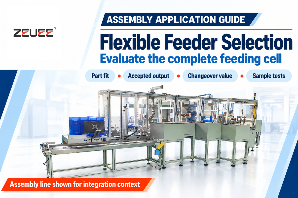
A flexible feeder scatters loose parts in front of a camera so it can identify suitable parts for robotic picking. Choose one for changing part families when the complete cell meets your accepted-output target and the saved changeover time pays for the added equipment and integration.
Quick selection checks
- Part fit: separate, recognize, grip and place production samples.
- Output: count accepted parts at the cell exit over elapsed production time.
- Changeover: time the last good old part to the first good new part.
- Cost: compare installed cells with the same delivery scope.
- Acceptance: agree independent quality checks and trial coverage before ordering.
A flexible feeder uses controlled part motion and vision-guided picking to handle changing components. Its value depends on tested part compatibility, sustained good output and useful changeover savings.
High mix low volume feeding may justify additional adaptable equipment. A stable, high-volume job may favor a dedicated bowl. Compare parts feeding and orienting within the whole assembly process; the wider automated assembly machines guide explains feeding and assembly and inspection.
How a Flexible Feeder Works
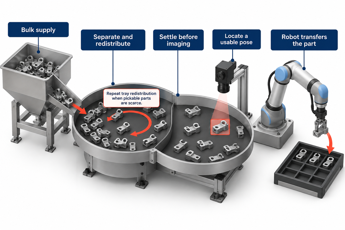
A flexible feeding system works similarly to spreading a handful of buttons out on a tray in order to pick one. Controlled movement separates and redistributes components, and a vision system finds a usable pose, and a robot transfers the component. The feeder, camera and robot repeat that loop as pickable parts become scarce. A3 describes vision-guided flexible feeding for bulk part singulation.
How does an automatic feeder work?
An automatic feeder supplies components to the next operation without an operator placing each component. A hopper replenishes the presentation area, while controlled motion or a shaped track moves parts toward a usable position. Sensors integrate delivery with downstream demand. In a flex feeder, a camera guides the robot instead of a mechanically fixed outlet.
The feeder surface may use vibration to move parts into position. A tray can present parts without giving every component its final assembly orientation; the gripper may complete that rotation during transfer. Thus, part orientation is a presentation task and a pick-and-place task.
Vibration can disturb an exposure or a pick. Where those operations can’t overlap, the controller must stop movement, wait for settling, and then acquire an image. A clear sequence prevents the robot from using coordinates captured before a part moved. This is one of the reasons the feeding device’s motion speed varies from the cell’s output.
Modern automation in modern manufacturing uses control systems to coordinate those operations. However, purchasing the feeding system presentation module leaves the robot, lighting, and end-of-arm tool and integration work to be completed.
Flexible Feeder vs Bowl Feeder: Where Each Wins
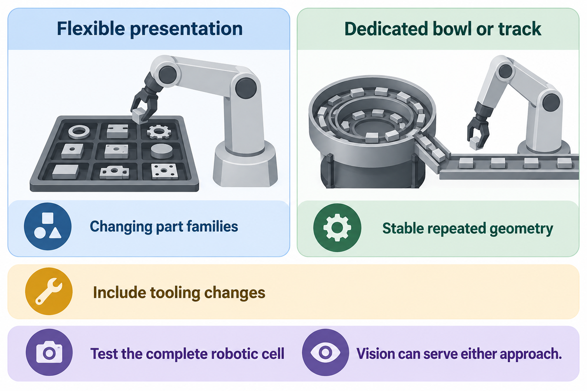
Frequent product changes favor flexible feeding when several variants share a workable surface and gripping arrangement. Dedicated bowl feeding is a strong candidate for a stable single part at high volume. The choice depends on which delivery mechanisms are tested and the mechanical changes between jobs. Vision-equipped bowl and track systems offer alternative trade-offs.
Flexible presentation
- Consider for changing part families.
- Budget for vision and robotic transfer.
- Include gripper and surface changes.
Dedicated bowl feeding
- Consider for stable repeated geometry.
- Budget for part-specific track tooling.
- Include tooling changes for variants.
Traditional vibratory feeders use mechanical features to orient parts. Vibratory bowl feeders can also use cameras and be programmed to reject parts. A 2022 University of Southern Denmark study presented a framework combining vision and mechanical traps on vibratory tracks. Its visual rejection mechanism was evaluated separately on six canonical part shapes. Flexibility is a degree of adaptability, rather than a simple division between machines with and without cameras.
| Decision factor | Flexible presentation | Dedicated bowl or track |
|---|---|---|
| Product mix | Several tested variants | Stable geometry or dedicated tracks |
| Batch changes | Recipe plus any hardware changes | Tooling and track adjustments |
| Final orientation | Vision and gripper coordinate it | Track tooling establishes the outlet pose |
| Required output | Test the complete robotic cell | Test continuous delivery under removal load |
| Transparent parts | Lighting and pose ambiguity matter | Mechanical selection may help |
| Entangled parts | Redistribution may not separate them | Track tooling may also struggle |
| Cosmetic surfaces | Check contact and recirculation damage | Check rubbing along the track |
| New variant | Assess surface, vision, grip and fixture | Assess new tooling and setup effort |
| Buying boundary | Include all cell interfaces | Include outlet handling and buffering |
For lines that run one component throughout a shift, reduced downtime from a new feeding solution may matter less than steady delivery. For short batches, faster changeovers can matter more. Keep a traditional bowl in the comparison until both arrangements are tested with the same parts and demand.
Part Suitability: Shape, Surface and Vision
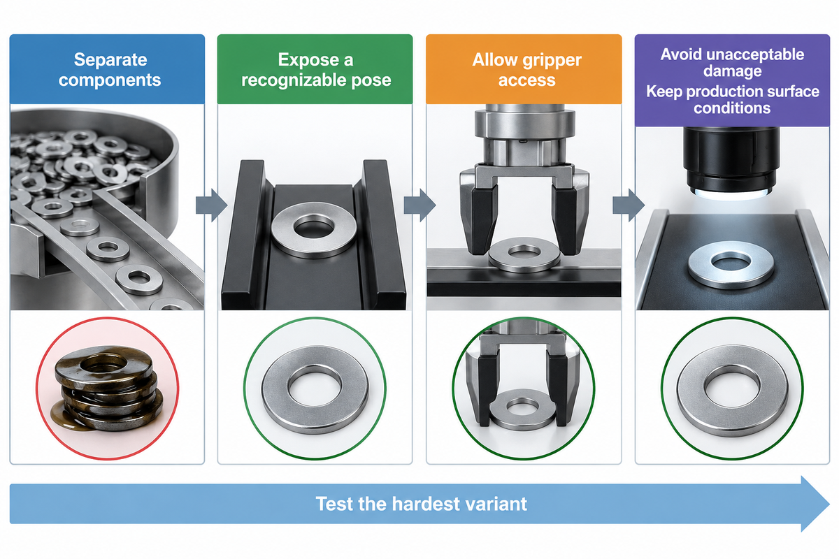
The suitability of components typically requires four successes: components must separate, reveal a recognizable pose, permit the gripper to access them and withstand handling without unacceptable damage. A camera may capture an outline that solves only one of these requirements. Oil, transparency, nesting and interlocking geometry can stop a seemingly suitable component before it reaches assembly.
“Production-level parts are needed during the design stage of a vision solution”
NIST’s perception research identifies a number of factors that affect robotic perception, including the material and surface finish of components. A silhouette may reveal an edge, but may hide the top feature of components that differentiates two orientations. Lighting must expose the feature needed for the next process step.
Which flexible feeder is best?
The production platform, lighting and gripper must be selected together for the production part family; then choose the complete cell that meets accepted output and changeover cost requirements. The hardest production variant and its surface condition should be selected first. A larger tray doesn’t help if features of the part aren’t accessible or if the parts stick to each other.
| Part condition | Likely difficulty | Selection response |
|---|---|---|
| Flat opaque components | Overlap hides edges | Observe separation and pickable population |
| Clear molded parts | Weak contrast or hidden surfaces | Compare lighting against the needed feature |
| Reflective metal | Glare changes with pose | Use production finish in imaging trials |
| Thin washers | Stacking and adhesion | Check double picks after replenishment |
| Springs and hooks | Interlocking | Assess separation before vision work |
| Delicate parts | Contact damage | Inspect after repeated handling |
| Similar variants | Incorrect recipe or mixed lots | Check variant identification and purge |
| Complex parts | Few accessible grasp poses | Validate gripper clearance and placement |
| Oily components | Adhesion and changing appearance | Keep normal surface condition in samples |
In December 2013, a user on Practical Machinist described small lightly oiled washers that stuck together during a proposed picking task. The user was trying to combine different washer combinations, and providing a single diameter wasn’t the whole problem. During the discussion, a respondent read the washer minimum thickness as 0.06″; the questioner corrected it to 0.006″. Making a ten-fold adjustment to the thickness substantially changed the discussion. The sample lesson is to preserve the condition of the washers as they’re produced, and identify the correct thin variant. In addition, count double-picked or stacked washers separately.
A wide variety of parts can share a platform, but the tested envelope must contain the awkward members of the family. Cleaning samples solely for a demonstration removes the very condition the production system must be able to process.
Throughput: Count Good Parts at the Cell Exit
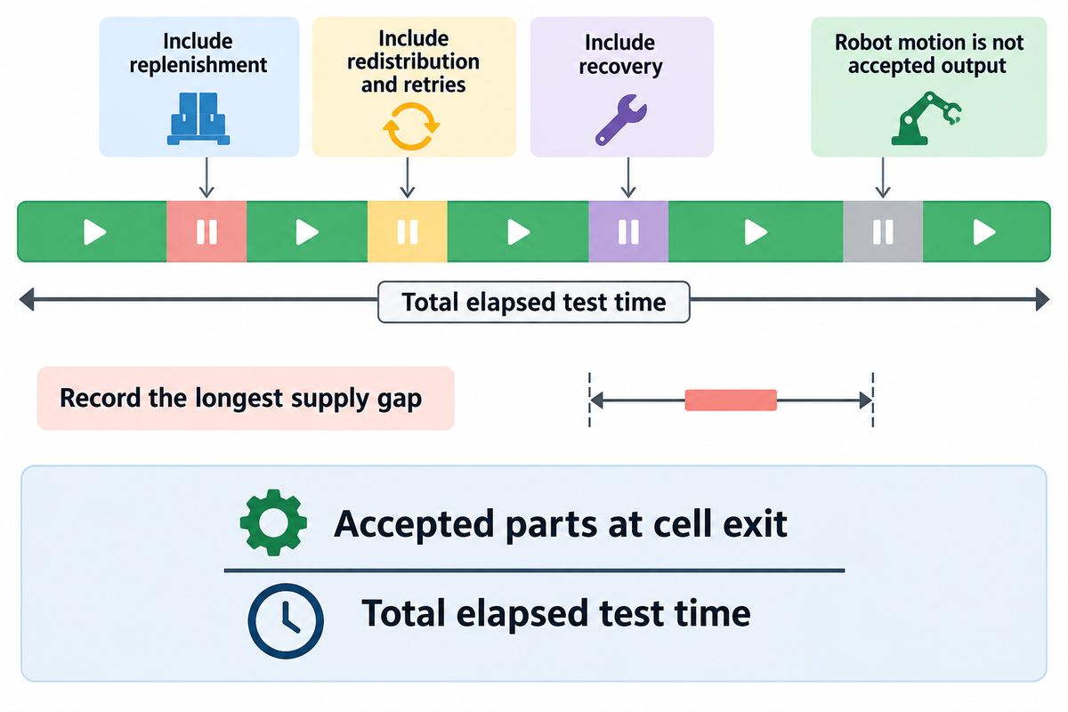
Acceptable output is the number of good parts delivered to the next operation, divided by the total elapsed time for that test. Consider replenishment, redistribution, retries, and recovery in determining total elapsed time. A robot cycle, camera detection rate, or other similar metric defines a component operation; the concern is correctly oriented parts that are ready for use.
The Refill-to-Recovery Clock
The Refill-to-Recovery Clock follows each interruption from fresh material entering the hopper to stable delivery returning at the exit. Replenishment can obstruct the tray, making features hard to see, and even trigger redistribution. Logging the cause of each pause can help determine if a particular step is the limiting step.
A typical flexible feeder cycle time includes dependencies. For example, a blocking conveyor can withhold transfer permission. Imaging may have to wait for a surface to become still. Robot motion can block the camera’s view. Placing a part may have to wait for equipment downstream to give permission. A feeder can’t remove the delay caused by a full downstream fixture. The production line automation guide covers this wider coordination problem.
Consider an illustrative assembly job requiring 20 accepted parts/min. During a 60-minute screening run, the cell delivers 1,440 independently accepted parts, so its observed output is 1,440 ÷ 60 = 24 parts/min. Suppose the same run contains a 30-second refill pause, a 20-second redistribution pause and a 40-second recovery. All these pauses are within the 60-minute denominator. Eliminating them would provide a measure that’s different from elapsed production output. The average output of the illustrative example, however, exceeds the target. The longest supply gap still matters, especially when the downstream station has little buffer. In such a case, capture this supply gap, along with the average, for various hopper levels and difficult variants, before arriving at an acceptance decision.
NIST’s assembly test-method work uses the task-based evaluation of repeated measurements to build confidence. Incorporate that into your actual transfer and assembly requirement. Track wrong orientations, double picks, damaged parts and manual interventions even if the robot indicates that it has completed the motion.
Flexibility and scalability are different buying decisions. Additional production lines or parallel stations may increase capacity, but each comes with more controls, floor space and service work. Increased production has value only if the downstream process and demand can use it.
Changeover Economics: Price the Whole Feeding Cell
Whole-cell cost includes feeder, robot, vision, gripper, controls and commissioning. Compare that installed scope with the alternative and value useful hours saved per year. Fast changeovers create a financial return only if recovered time reduces paid work or produces saleable output at a constrained operation.
NIST MEP defines quick changeover as the last good piece of the current run to the first good piece of the next run. Recipe loading only takes up part of that time. Lot clearance, mechanical retooling, camera checks and the first accepted assembly can remain on the critical path.
One historical price illustrates the importance of scope: Automation World reported on November 30, 2020 that Engineered Vision’s Flex-Bot started at USD 75,000 including programming and installation. The package included a robot, vision, feeding equipment, tooling and controls. That dated product announcement belongs to Engineered Vision; obtain current, matched-scope quotations for today’s comparison.
Changeover Cash-Value Worksheet
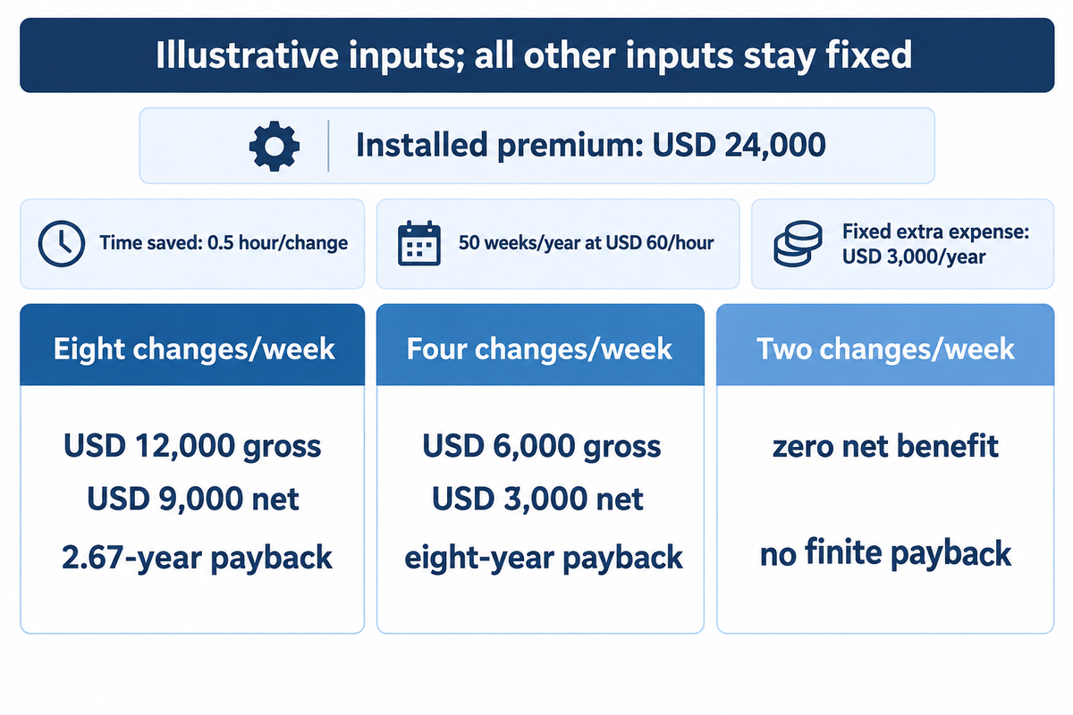
For this illustrative calculation, assume a USD 24,000 incremental installed premium, eight changes/week, 0.5 hour saved/change, 50 operating weeks/year and USD 60/hour of realizable value. Extra annual running and support expense is USD 3,000/year. These are chosen planning inputs, not a supplier quotation or a ZEUEE operating result.
| Input or result | Value | Meaning |
|---|---|---|
| Installed premium | USD 24,000 | Flexible cell minus matched alternative |
| Weekly changes | 8 changes/week | Changes that save useful time |
| Saving per change | 0.5 hour/change | Measured whole-changeover difference |
| Operating year | 50 weeks/year | Planned annual schedule |
| Annual recovered time | 200 hours/year | 8 × 0.5 × 50 |
| Realizable hourly value | USD 60/hour | Cash saving or usable capacity value |
| Gross annual value | USD 12,000/year | 200 × 60 |
| Extra annual expense | USD 3,000/year | Added support and operating expense |
| Net annual benefit | USD 9,000/year | 12,000 − 3,000 |
| Simple payback | 2.67 years | 24,000 ÷ 9,000 |
Now consider a production planner whose schedule changes from eight to four weekly changeovers while every other example input stays fixed. Recovered time falls to 100 hours/year, worth USD 6,000/year before the extra USD 3,000/year expense. Net benefit becomes USD 3,000/year, and simple payback stretches to eight years. At two changes/week, the same calculation leaves zero net annual benefit and no finite simple payback. The equipment hasn’t become slower; the schedule supplies fewer opportunities to recover useful time. Finance should also reject double counting: if the USD 60/hour already values recovered capacity, adding a second labor saving for the same hours requires a separate, real reduction in spending.
Simple payback neglects financing, taxes, and the timing of later cash flows. For longer projects, use the company’s investment model and a realistic representation of production needs. A promise of reduced downtime merits a measured baseline and identifiable use of the time recovered.
Integration: Robot, Gripper and Control Systems
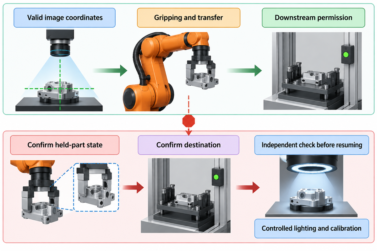
The flow of material to the robot must be coordinated with the availability of the part and valid image coordinates, gripping, transfer and downstream permission. A feeder system works only if every controller knows which event starts the next action and how to recover after an interrupted cycle. Define the recovery sequence while developing the normal automation process.
The HMI should select the matched feeder, camera and robot recipe. A new program can orient and feed a different component, but dedicated tooling may still change at the gripper or fixture. Flexible feeders provide a reusable presentation method; however, they don’t automatically render all adjacent production processes reusable.
Consider a stop after the robot grips a part but before part placement. Restarting the feeder alone can leave the controller uncertain whether that part has entered the assembly. The sequence requires a known held-part state, a defined destination and an independent check prior to automatic operation resuming. Normal-cycle timing can obscure risk of errors. Having clear recovery logic minimizes the risk of errors.
Vision technology in robotic transfer also requires camera-to-robot calibration and controlled lighting. Position recognition and finished quality are different jobs; the vision inspection systems guide explains the inspection side of that interface.
Industry 4.0 connectivity can log stops and recipe changes, but useful records need a cause and timestamp, rather than only a total cycle count. For robot safety scope, ISO 10218-1:2025 addresses the robot, while integration and applications belong to Part 2. Component compatibility and complete-cell acceptance require separate attention.
Suppliers and Integrators: Who Owns Each Interface?
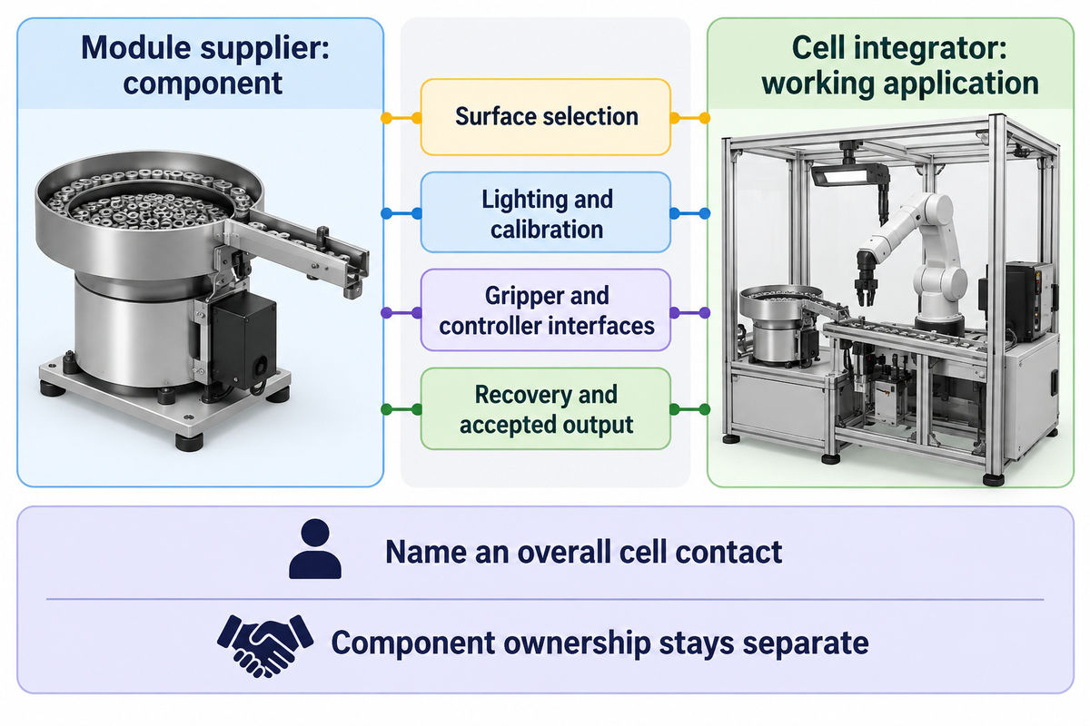
A module supplier provides a component and a cell integrator provides the working application and its delivery. Sometimes, these roles are in different companies, but other times they’re in the same company. For every hand-off, assign an owner. This ensures that problems between the feeder, vision and the robot have a clear route for diagnosis and correction.
BARA’s integrator description includes design, manufacture, assembly, programming, installation and aftersales, with internal or external resources. It can use its own or external resources. Integration therefore goes beyond supplying a module from a catalogue. It does not transfer ownership of another manufacturer’s component technology.
Retain named responsibility for surface selection, lighting and calibration, gripper clearance, controller communication, recovery and final accepted output. For flexible feeder systems, a single overall cell contact should coordinate these interfaces, even if different specialists perform the tasks.
ZEUEE’s automated assembly equipment is the starting point to discuss the feeding task in an assembly project from a commercial viewpoint. Determine the required feeding solution and delivery scope and compare offers.
Sample Tests Before You Order
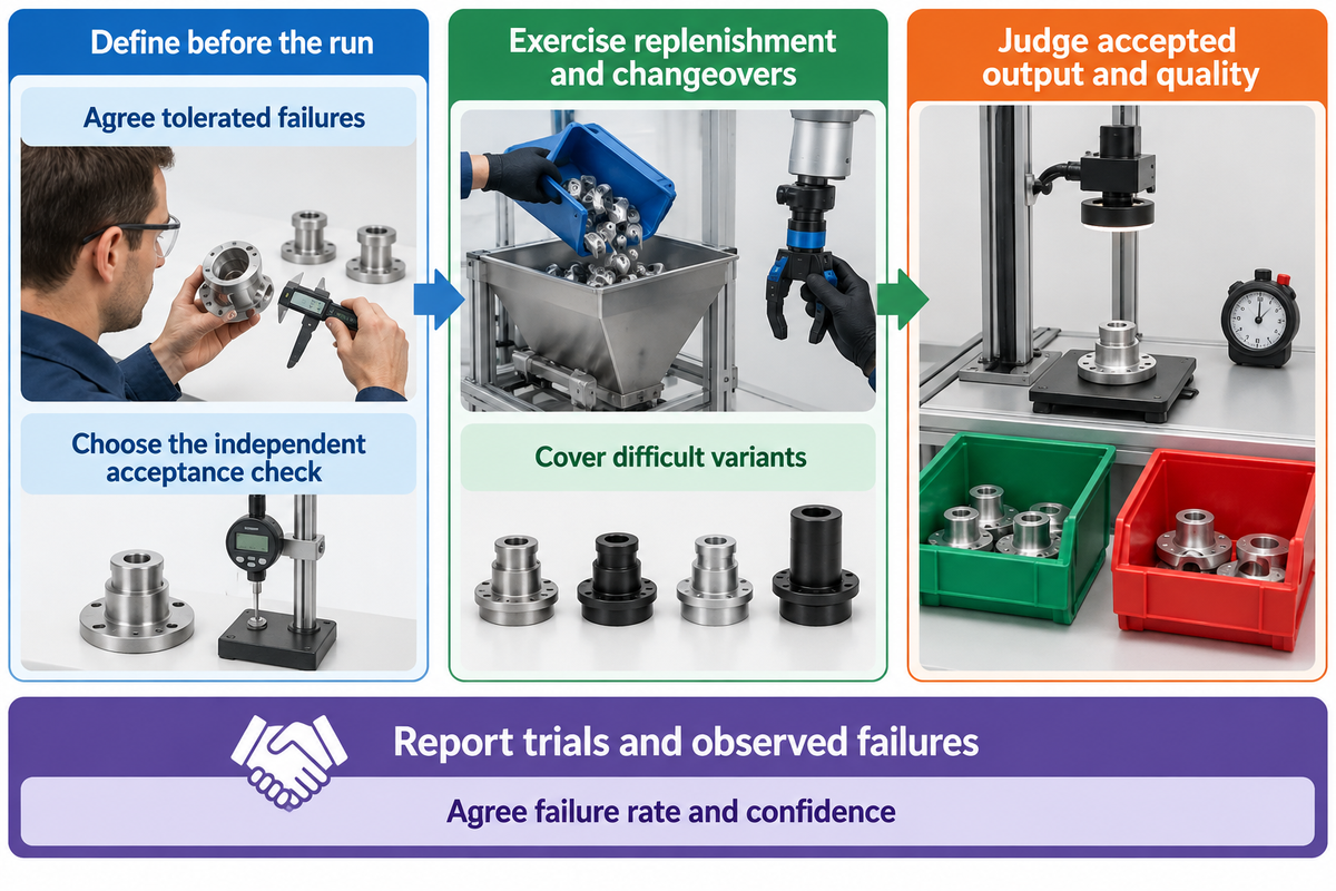
A flexible feeder acceptance test should measure accepted output and part quality and prove recovery under production-like conditions. Before the run, determine the sample family and test duration, the number of failures that will be tolerated and the independent acceptance check. Perform an independent acceptance check and cover replenishment, changeovers and steady operation. A short demonstration addresses the conditions it actually exercises.
For initial screening, an example 60-minute run at a 20 parts/min job target provides a means to capture interrupts. For the final evaluation, the length of the run must cover the actual batch pattern, replenishment and difficult variants. A long duration doesn’t ensure adequate coverage when easy parts are circulated over and over again.
Include in the trial
- Use normal production surface conditions.
- Exercise low hopper levels and replenishment.
- Check accepted parts independently.
- Repeat the whole product changeover.
Avoid in the trial
- Wash away a normal sticking problem.
- Remove recovery time from elapsed output.
- Count every completed motion as a good part.
- Time only the recipe selection.
Quality should come from downstream inspection, an agreed gauge or reviewed recordings, independently of the feeding camera’s success label. False accepts and rejects should also be included. A reject action can disturb a nearby good component, so review the result of the action as well as the image classification.
For every percentage of success recorded, report the number of trials and observed failures. Agree on the maximum failure rate and the confidence level, and then select a sample plan based on those values. NIST’s exact-binomial guidance distinguishes a success proportion from confidence limits and explains why caution is needed for small sample sizes or small failure numbers. Repeated handling of a component can also result in failure correlation. In those cases, preserve lot and operating condition coverage.
Attach these fields to the purchase specification: part revision and finish; variant dimensions in mm and mass in g; output in accepted parts/min; longest supply gap in seconds; replenishment count; observed wrong, missed and double picks; damage criteria; intervention time in minutes; and last-good-to-first-good changeover time. Determine who’s inspecting the results and who’s responsible for correcting the results if it falls outside the acceptance criteria.
For a proposed ZEUEE assembly project, send the assembly application requirements with representative parts, production demand and the downstream acceptance rule. Discuss how to automate the task, while keeping the tested scope in the quotation visible.
Frequently Asked Questions
What Is the Principle of a Flexible Feeder?
Controlled motion presents loose components for vision-guided robotic picking.
The surface spreads and redistributes parts so the camera can locate a usable pose. A robot then transfers a selected component, and movement resumes when too few pickable parts remain. Mechanical orientation tooling is partly replaced by motion and image processing, while the gripper and downstream task still determine how each component reaches assembly.
When Should You Use Robotic Bin Picking?
Use bin picking when the task is direct removal from a container and heap access is workable.
Parts must be recognizable and reachable by the gripper while they remain in that container. A flexible feeder first redistributes components onto a controlled presentation surface. Compare the two approaches using production samples and the required delivery pose. Bulk behavior, gripper clearance and sustained accepted output determine which arrangement can perform the actual transfer task.
What is a Vibratory Feeder Bowl and What Does it Do?
A vibratory bowl moves bulk parts along a shaped track toward a repeatable outlet.
Part-specific tooling selects or rejects orientations as components travel, and an outlet presents them for removal. Dedicated tooling is useful when stable geometry supports reliable mechanical selection. Cameras can also inspect components along a bowl or track arrangement. Compare its continuous delivery and variant-change effort against the complete flexible alternative under the same downstream demand.
Can one feeder handle every part in a product family?
One platform can handle multiple variants when they fit its tested presentation and picking envelope.
Different part sizes may still require different surfaces, lighting or grips. Test the difficult family members, including components that nest or stick together, before committing all variants to one platform.
Does a faster recipe change guarantee faster production changeover?
Recipe selection shortens one task; the complete changeover also includes hardware and first-part acceptance.
Clear the old lot, change any gripper or fixture, confirm the imaging setup and produce a good new assembly. Time the interval from the last accepted old part to the first accepted new part under the same staffing and material conditions. Key advantages such as fast changeovers become financially useful when that measured difference releases paid work or constrained production capacity.
Does the robot need to be replaced for a new part?
The robot can often remain when its reach, payload and motion still suit the new task.
The gripper, lighting, presentation surface or fixture may need changing. Evaluate those items together before treating the introduction of multiple part types as a software-only change.
Which trial results belong in the purchase specification?
Include accepted output, quality failures, interruptions, recovery and complete changeover results.
State the tested revisions, production surface conditions and hopper levels. Record sample count, allowed failures and the agreed confidence target. Identify the independent good-part check and the observation period. Those terms connect automated production performance to the delivered cell, rather than to an isolated feeder demonstration.
Comparison methods combine relevant engineering examples and illustrative planning examples. Products of suppliers, research, and quoted opinions are attributed to their respective owners.
References & Sources
- NIST: Perception Performance of Robotic Systems.
- NIST: Assembly Performance Metrics and Test Methods.
- NIST MEP: Lean and Process Improvement, quick changeover.
- NIST Dataplot: Exact Binomial Confidence Limits.
- A3: Robotics Vision at a Glance, July 2013.
- Haugaard and colleagues: vision-trap feeder research, 2022.
- David Miller, Automation World: Flex-Bot report, November 2020.
- ISO: ISO 10218-1:2025 public catalogue and scope.
- Automate UK / BARA: Robot Integrator Standard overview.
Related Articles
WHY WE WRITE THIS
About ZEUEE Engineering Insights
ZEUEE shares technical guides based on real automation project experience. Since 2005, we have designed and manufactured non-standard automation equipment for connector assembly, wire harness production, robotic lines, vision inspection, and smart factory upgrades.
Founded in 2005
20,000 m² production base
120+ specialists
150+ R&D patents
ISO9001:2015 certified