Get in touch with Zeyu lntelligent Industrial Company

Hinge Assembly Machine Guide: From Parts to a Working Joint

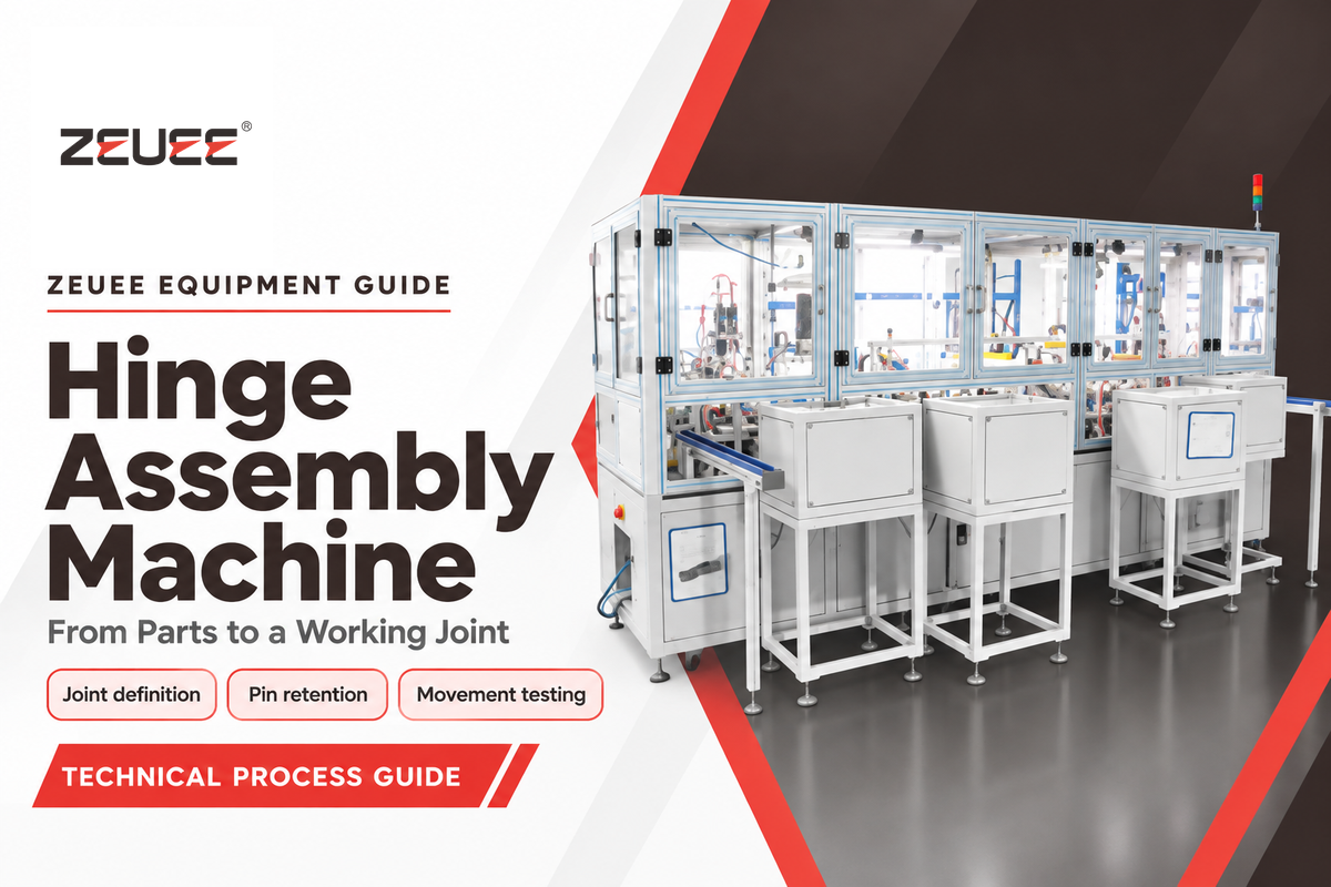
A Hinge Assembly Machine combines hinge parts with controlled feeding, placing and fastening them. The resulting hinge must allow intended movement, but hold its pin or pivots in place. An industrial machine that inserts a pin successfully may still produce a hinge that binds.
A Hinge Assembly Machine feeds and locates components, joins them, and checks the assembled hinge. Pin retention, free movement and soft closing need different checks. Define the finished joint before choosing the machine layout.
Quick Specs: Define These Before Comparing Equipment
| Design input | Record for your hinge |
|---|---|
| Incoming condition | Finished leaves, pins, spring, bearings or sealed damper |
| Dimensions | Pin and finished bore limits in mm; datum and surface finish |
| Joint behavior | Retention method, axial play in mm, movement angle in degrees |
| Functional test | Torque in N·m or closing time in s under specified conditions |
| Production comparison | First-pass good parts/min, staffing and complete changeover time |
- A pin can be retained in one member while another member rotates around it.
- Automatic assembly controls joining; product durability still needs its own test.
- Semi-automatic describes operator involvement. Rotary describes the transfer layout.
- The useful production rate counts accepted hinges and the time lost between cycles.
What Does a Hinge Assembly Machine Actually Assemble?
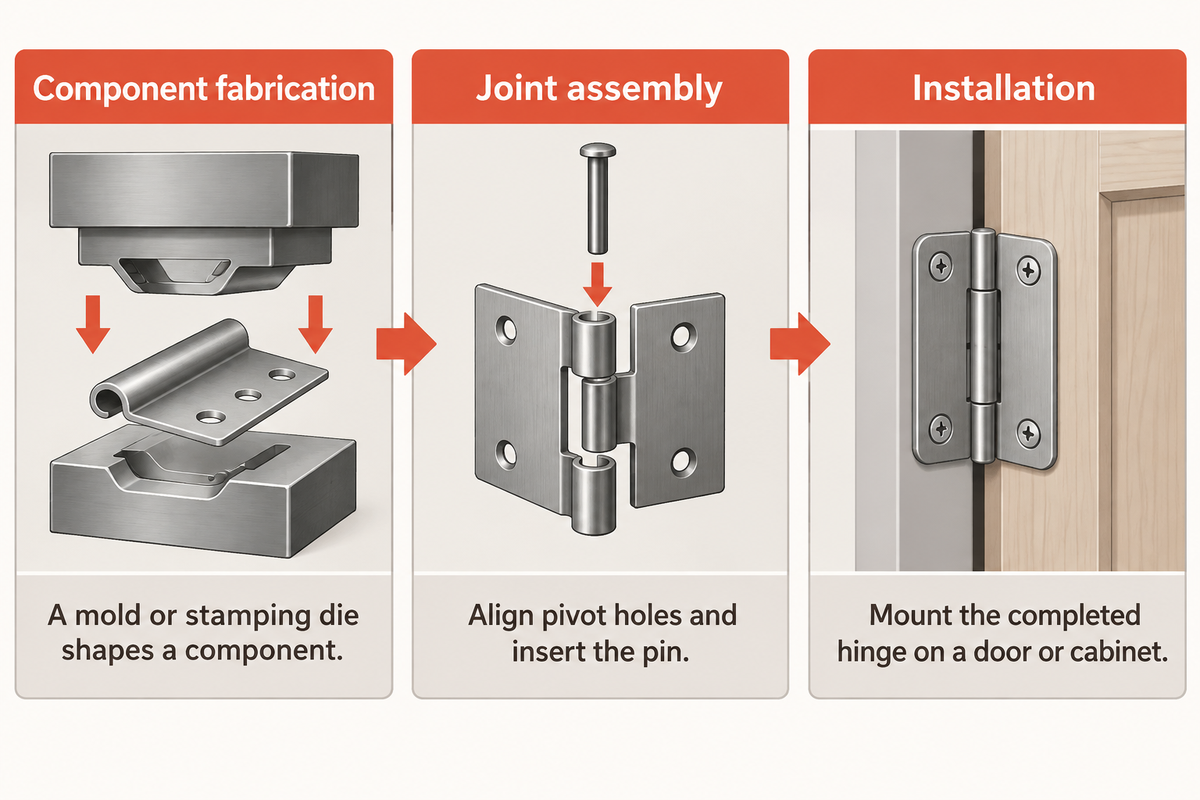
The equipment combines components to form a hinge or one of its subassemblies. A concealed furniture hinge may include a spring and several pivots. A hydraulic hinge may receive a purchased damping unit during assembly rather than have its damper manufactured inside the cell.
There are three tasks that may be confused with each other – metal component fabrication, joint assembly, and the final installation of the completed hinge on a door or cabinet. Leaf fabrication may happen upstream. A component may be stamped, cast, or machined. A mold or stamping die shapes a component; assembly fixtures locate formed components, while installation involves drilling mounting holes. A machine factory must have a clear incoming-parts list to tell the different tasks.
How are hinges assembled?
Hinges are assembled by aligning the pivot holes of mating components and inserting a pin or other fastener. Additional operations can place washers, preload a spring, dispense lubricant or install a damping module. Finally, the result is inspected and movement of the joint is checked against the product drawing.
The sequence varies with the joint. A continuous hinge has one handling problem, and a small clip-on cabinet hinge has a different one. A friction hinge needs some controlled resistance; a soft close hinge needs a defined closing response. The BHMA overview of butts and hinges separates friction, wear and cycle testing, which is a reminder of their different meanings.
Regarding a ZEUEE equipment discussion, the Hinge Assembly Machine solution page addresses the commercial aspect of the project. For the technical discussion, first describe the components that enter the cell and the assembly that leaves it. That boundary precludes comparing a pivot subassembly quote with a complete, finished hinge line.
Define the Joint Before Designing the Assembly Cell
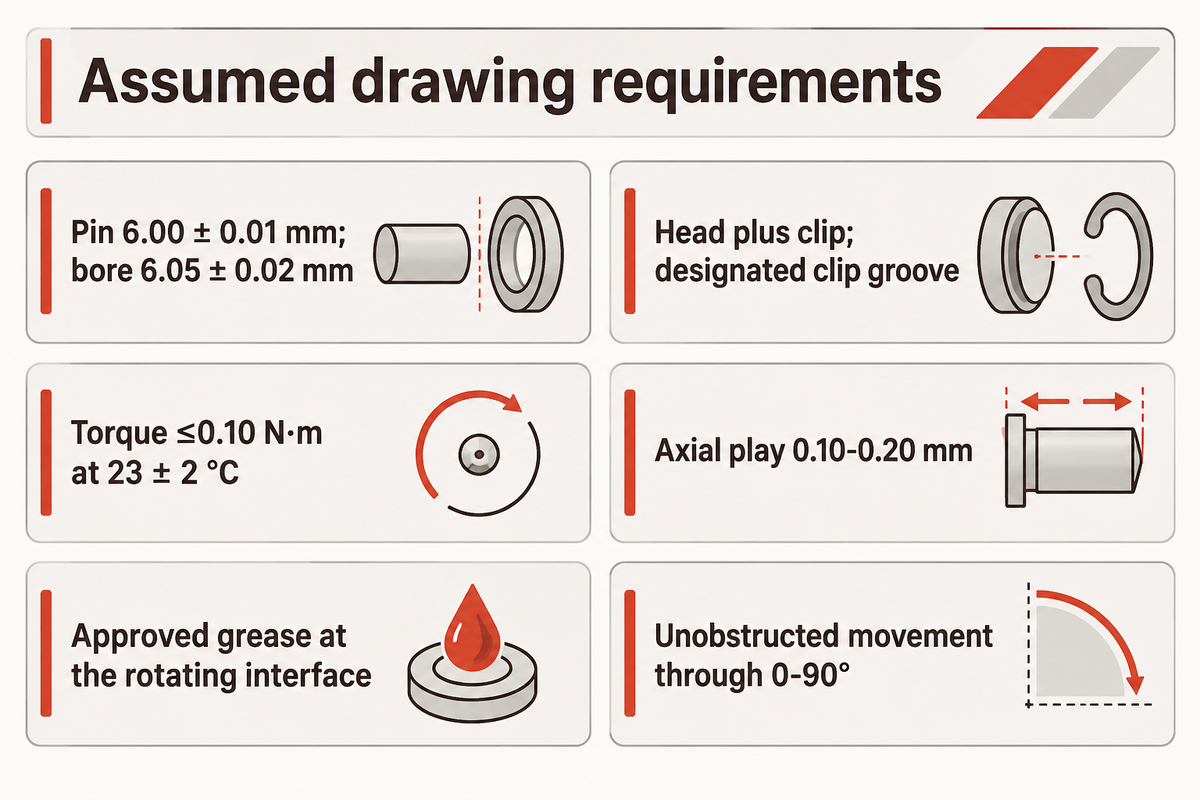
A definition of a usable joint identifies the locating surfaces and the member that’s retained and the surface that moves. Tighter positioning alone will not solve a mismatch between the drawing, the pin-retention method and the movement the finished hinge must deliver.
Consider a pin fixed in one leaf with another leaf turning on its middle span. A bushing adds another interface: its outside must stay in its housing while its inside permits the intended rotation. A washer stack adds axial dimensions that a pin-diameter check will miss.
6-Check Joint Definition Sheet
Running example: Free-Running Joint Example. The filled entries below describe a proposed joint with a headed 6.00 mm pin and a retaining clip. They’re assumed drawing requirements for explaining the method. Replace the entries with the approved requirements for your product.
| Check | Example entry | Consequence for assembly |
|---|---|---|
| Geometry and datum | 6.00 ± 0.01 mm pin; finished rotating bore 6.05 ± 0.02 mm | Locate the knuckles to their common axis; measure finished surfaces |
| Pin retention | Head plus clip; designated clip groove | Inspect clip seating separately from pin insertion |
| Movement resistance | Drawing target ≤0.10 N·m at 23 ± 2 °C | Use a defined torque test, with fixture friction accounted for |
| Axial clearance | 0.10–0.20 mm end play | Control the leaf and washer stack independently of bore fit |
| Lubrication | Drawing-approved grease at the rotating interface | Define location and quantity; keep the retaining feature clear |
| Functional behavior | Unobstructed movement through 0–90° | Check motion after retention, not before it |
This is a flexible sheet that can be adapted to a measuring plan by the quality staff and used to identify operations needing controlled tooling by the production staff. The Wang, Huang and Chang tolerance-analysis paper presents the dimensional and geometric contributors to assembly function. Its numerical research example supports attention to the full dimensional chain; its reported optimization gains are not hinge-machine performance figures.
A drawing without a datum leaves the fixture designer guessing as to which surface controls the joint. Likewise, a request for “good accuracy” requires a measurable feature of the product. The custom assembly machine guide describes how to define the project scope based on these inputs.
An example joint requires 0.10 – 0.20 mm of axial play and a movement ceiling of 0.10 N·m. A fixture that holds the pin within its axis still may be too tight for the washer stack. Showing both of these requirements on the joint sheet allows the missing operation to be identified before tooling is made.
Feed and Orient Leaves, Pins, Springs and Dampers
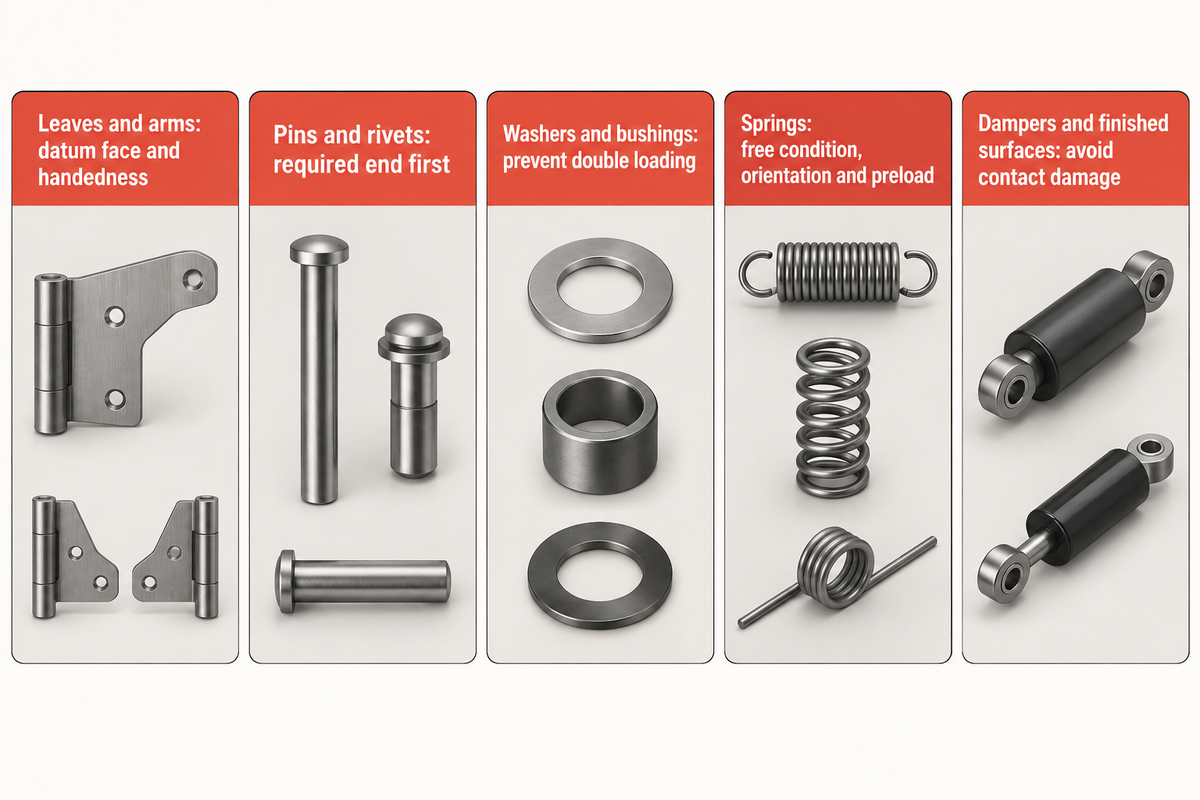
Feeding must provide the correct component, in the correct orientation, at the location where the next operation is able to receive it. Part shape and symmetry influence the tooling; surface condition changes contact and sliding behavior. Springs, finished leaves, and sealed dampers can require different presentation methods within the same automatic production line.
In their vibratory feeder bowl analysis, Green and Kreul report orientation stations where parts are accepted or rejected. Their study focused on the bowl’s vibratory system. It doesn’t specify the speed of the hinge feeder and the springs of the model are suspension elements as opposed to loose hinge springs.
Match the presentation method to the part
- Leaves and arms need a defined datum face and handedness. A nest may accept a reversed part even when the outline looks similar.
- Present pins and rivets with the required end first, then control the path into the insertion tooling. Headed and headless pins need different handling.
- Washers and bushings: prevent double loading and inspect the feature that distinguishes the correct component.
- Springs: define the free condition, orientation and assembly preload. Tangled pieces may require separation before placement.
- Dampers and finished surfaces: compare trays, magazines or robotic placement with bulk handling when contact could mark or damage the part.
Let’s say a tray has 96 finished arms and the next station consumes 8 parts/min. The nominal tray interval is 96 ÷ 8 = 12 min. The same operator also loads springs at a neighboring station and if these replenishments happen together, the automatic joining cycle can wait. Responses to this interruption can include changing the size of the buffer, tray size, or replenishment frequency. The useful trial records how parts arrive and how often the station waits; a close-up video of one successful insertion cannot reveal the replenishment pattern.
NIST’s assembly performance research lists among factors affecting assembly tasks, size, symmetry, fixturing and obstructions. A 2D image can help identify orientation, while a 3D feature may need another viewing angle or sensor. Detection must address the true wrong condition including double parts and absent parts. Scratches first appearing during transfer can come from hinges making contact with a guide instead of their intended datum.
Besides hardware, other elements contribute to feeder purchase cost. Consider the actual finish, incoming packaging and variant mix when comparing bowl feeder tooling and cost. The 96-part tray example provides 12 min of nominal supply at 8 parts/min; consuming the last part before replenishment is complete creates a supply loss regardless of joining speed.
Align the Knuckles and Insert the Hinge Pin
Pin insertion relies on a supported, aligned path through the holes. The fixture should locate the part without distorting it, and the insertion tool must position the pin to the seating location. Joining signatures are verified through the measurement of force and displacement. Anomalies, such as a missing part, obstruction or the pin being seated incorrectly, may produce an unexpected force-and-displacement signature.
A pneumatic cylinder and its control valve provide the movement. Also, a servo press offers a different control mechanism. All the methods require a defined mechanical reference. Tool deflection, a tilted leaf or a burr can change the measured force. Increasing pressure to push through a repeatable obstruction can mark the part or hide an upstream problem.
The 2026 ASSEMBLY report on force and displacement monitoring describes measurement systems on manual and automated presses. Establish the trace using representative, conforming components, and deliberate, controlled defect conditions. Seating and movement checks should be paired with the trace. Identical peak forces can occur at different positions.
Work through the clearance limits
Engineering Note: Diametral Clearance
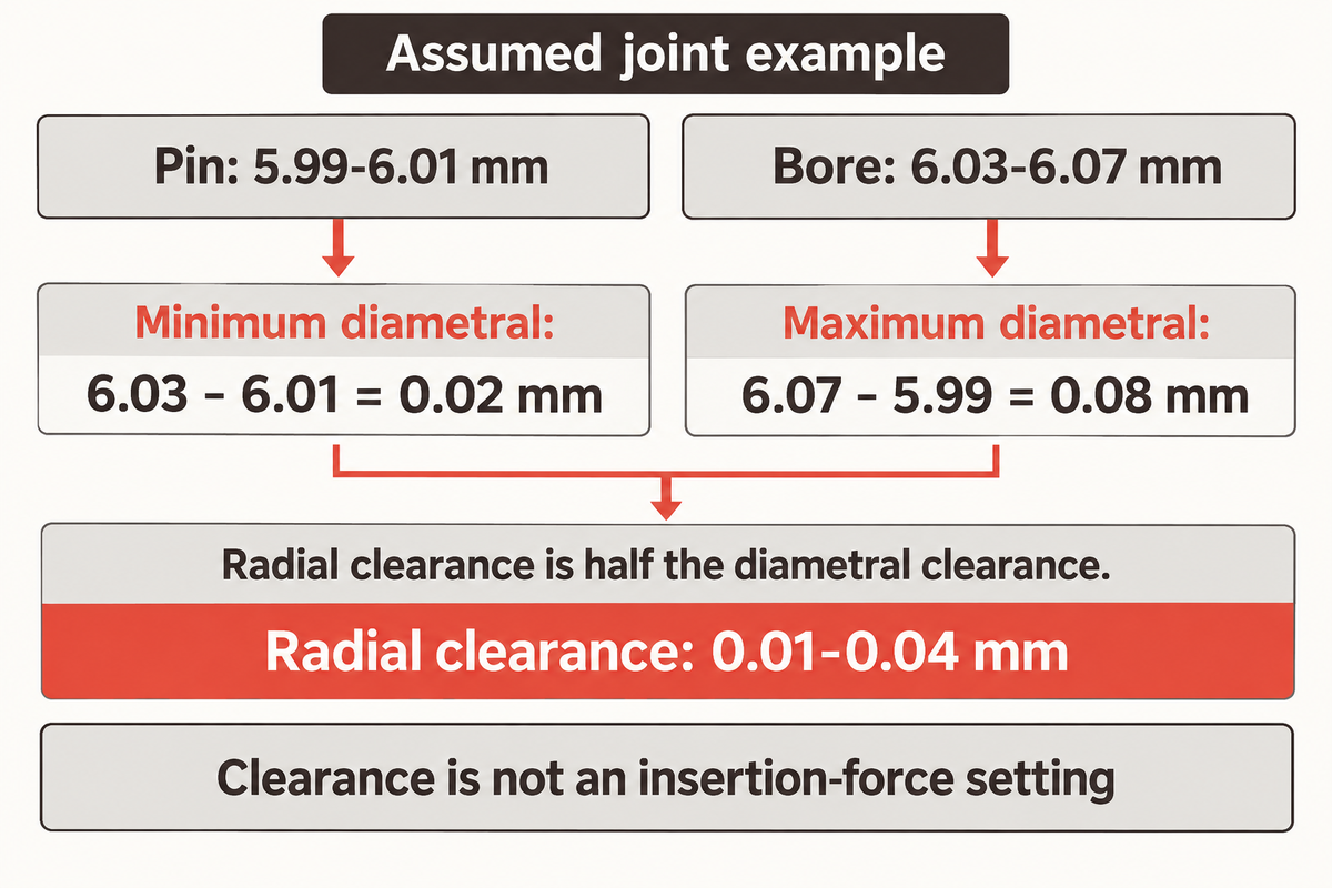
In the Free-Running Joint Example, the pin spans 5.99–6.01 mm and the finished bore spans 6.03–6.07 mm. Minimum diametral clearance = 6.03 − 6.01 = 0.02 mm. Maximum diametral clearance = 6.07 − 5.99 = 0.08 mm. Radial clearance is half those values: 0.01–0.04 mm. The arithmetic addresses size limits; coaxiality, surface texture and loading still belong in the design review.
The NIST dimensional calibration paper describes uncertainty as limits on a measurement estimate. Choose a measurement system whose uncertainty supports the product decision, and consider contact, temperature and the measurement system setup. Display resolution of the system isn’t the measurement system uncertainty.
“traceability alone does not signify or guarantee fitness for purpose”
Before purchasing a tighter press, separate the product tolerance from the uncertainty of the measurement and the positional repeatability of the mechanism. The example’s 0.02 mm minimum diametral clearance isn’t an insertion-force setting. A pin can meet its diameter limit and still encounter a misaligned hole; the force trace and the dimensional record answer different questions.
Retain the Pin: Press Fits, Riveting, Staking or Screws
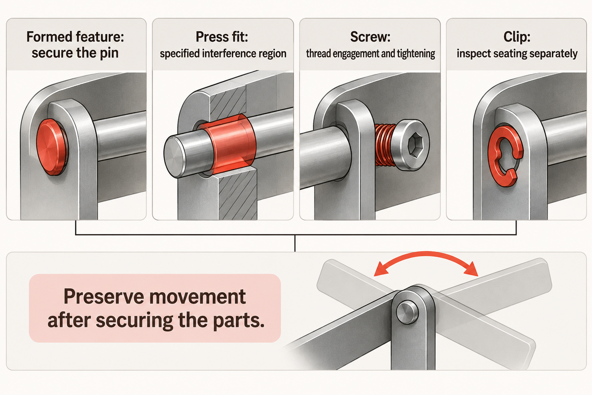
Retention of the pin prevents migration in unwanted directions. The joining surfaces can allow for relative motion or offer friction. The retention method follows the hinge design: an interference region, a formed head, a staking feature, a clip or a threaded fastener. The joining station must preserve the required movement after securing the parts.
Riveting or staking provides a retaining feature that can secure the pin. In the case of a screw-retained pivot joint, thread engagement controls retention; a press fit relies on its specified interference region. They’re, however, different mechanisms. A machine builder shouldn’t substitute one for the other just because the cycle time for the machine is faster.
Joint features that change the assembly sequence
The features described below may be present together in a design. They don’t represent nine machine families that are mutually exclusive. Refer to the matrix to determine the function of each feature.
| Feature | Assembly consequence | Output to define |
|---|---|---|
| Removable pin | Preserve the extraction path and retaining feature | Pin position in mm; removal condition |
| Permanently retained pin | Form or engage the specified retention feature | Head dimensions in mm; retention test in N |
| Pressed bushing | Support the housing and control bushing seating | Seating depth and installed bore in mm |
| Washer or bearing stack | Control part presence, order and stack height | Axial play in mm |
| Multiple linked pivots | Retain alignment across successive joining stations | Pivot location in mm; movement angle |
| Spring preload | Orient and load the spring before capture | Torque in N·m at specified angles |
| Purchased sealed damper | Place and connect the qualified module | Closing time in s at defined temperature/load |
| Screw-retained pivot | Start the thread correctly and control tightening | Torque in N·m and fastener seating |
| Friction stack | Control the compression of friction interfaces | Breakaway and running torque in N·m |
ASSEMBLY’s explanation of orbital and radial forming describes progressive head forming and the possibility of a tight or loose fastening result. Tool shape, support and final geometry therefore matter alongside the forming motion. Its older machine-force ranges aren’t settings for a new hinge application.
With a moving pivot, excessive compression can turn a successful fastening operation into a binding joint. With a fixed pivot, a lack of retention can allow joint migration during use. In both of these cases, the purchase description should specify the type of joint response, rather than specify a maximum forming force.
For the Free-Running Joint Example, a seated clip can coexist with 0.10–0.20 mm axial play. Changing that clip to a formed end introduces a different axial stop, so the end-play and movement requirements need a fresh design review. The proposed 0.10 N·m torque ceiling remains a product requirement; the 0.02 mm minimum diametral clearance describes another interface. A stronger retaining operation does not automatically improve either result.
Lubricate the Joint and Verify Its Movement
Movement testing evaluates assembled hinges after retaining operations. Define the movement range, load applied, and test conditions. The behaviors of interest may include free rotation, friction torque, spring return, and soft closing. The quantity and location of lubrication should be included in the definition, because they may affect those behaviors.
For a hinge that’s free-running, breakaway resistance and running resistance should be defined separately. In a friction hinge, resistance to motion is due to friction. A closing hinge assembly machine may integrate a spring or damper and those affect the closing behavior. One open-and-close action can reveal an obstruction but does not reproduce long-term wear.
Which component is most critical to the quality of hydraulic hinges?
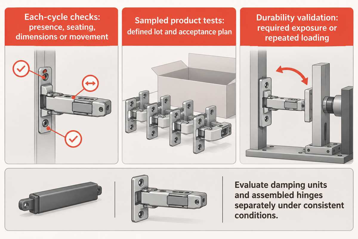
The damping module and geometry affect the integrated hydraulic behavior. A sound damper cannot correct a binding pivot or wrong spring orientation. In the presence of the specified load, evaluate the incoming damping unit and assembled hinges separately, with the closing angle, temperature and mounting arrangement held consistent.
In the case of automatic cabinet hinge assembly, a sensor can validate presence of the module and a functional station can evaluate the closing response. The feature of interest should be inspected for the defect. A camera looking at a damper housing can’t measure the internal behavior of the fluid in the damper. An electronic pass signal is only useful against the validated test requirement.
- Each-cycle checks: component presence, seating, selected dimensions or movement measurements.
- Sampled product tests: tests assigned to a defined lot under an agreed sampling and acceptance plan.
- Durability validation: product testing through the required exposure or repeated loading for the intended application.
NIST’s acceptance-sampling explanation distinguishes a lot acceptance decision from an estimate of lot quality. Successful completion of a destructive pin-retention test on a sample of the population doesn’t measure the quality of the entire population of hinges. Define the lot, sampling unit and acceptance criterion with respect to the test method.
BHMA’s public A156.1-2025 gives an example of Grade 1 performance of 2.5 million opening and closing cycles on a door of specified weight. This gives an example of product durability with defined scope. A quick check of factory motion serves a different purpose. It can’t be a substitute for required duration, loading conditions and other defined test conditions of the product.
Choose an Automation Level Around the Real Production Mix
Automation level states which tasks an operator performs, and rotary or linear layout states how work moves. Assess these independently against the production mix. A semi-automatic fixture may control a difficult joining operation, and a fully automatic assembly machine still relies on dependable incoming parts, material and inventory control and exception handling.
The example in the Assembly article on automated riveting describes an automation of a six-station system where the operator does the loading and unloading. The use of fixtures and part ID was emphasized as moving the task from the operator to the machinery. The question for the engineer is which tasks to automate, as opposed to whether use of a rotary table means an unattended assembly line.
NIST identifies high-mix, low-volume automation with collaborative options that balance speed, payload and integration constraints. Small batches don’t automatically rule out robotic assistance. A dedicated high-speed automated cell for high-volume production becomes attractive when its task, product mix and sustained good output justify the added tooling and support. A quotation labelled “full automatic” still awaits an explanation of operator tasks.
Compare good output over the same time window
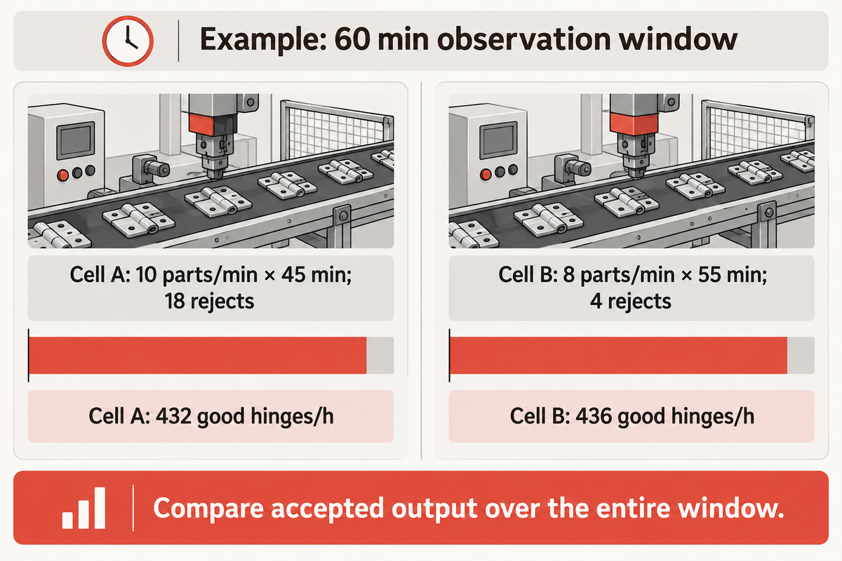
Example: Two cells each have a 60 min observation window and make one hinge per cycle. Cell A runs at 10 parts/min for 45 min and produces 18 rejects. Cell B runs at 8 parts/min for 55 min and produces 4 rejects. First-pass good output is:
- Cell A: (10 × 45) − 18 = 432 good hinges/h, or 7.20 good parts/min.
- Cell B: (8 × 55) − 4 = 436 good hinges/h, or about 7.27 good parts/min.
The faster moving cycle loses this comparison by 4 accepted hinges. Neither analysis accounts for later rework as first-pass good output. Real-time counts help locate loss. The final comparison needs the entire observation window. For a cost comparison, divide the hourly cost on the same staffing and cost basis by accepted hinges per hour; include changeover and planned maintenance when extending the comparison to a shift.
Where the rate is lost
The following loss map fills in stopped time for the same example. These are reasons to be recorded during an inspection, rather than assumed faults of a particular layout.
| Constraint to record | Cell A | Cell B | Decision owner |
|---|---|---|---|
| Replenishment waits | 6 min | 2 min | Production: supply method and buffer |
| Minor stops | 4 min | 2 min | Engineering: presentation and recovery |
| Inspection holds | 5 min | 1 min | Quality: classify true defects and false rejects |
| First-pass rejects | 18 hinges | 4 hinges | Production/finance: accepted output and unit cost |
What belongs in a hinge assembly machine quotation?
Quotations will be useful in evaluating the incoming hinge parts, operations, functional tests and delivered output for specific variants. All relevant documentation, drawings and components should be provided to substantiate output. Staffing, replenishment and changeover conditions should also be agreed to demonstrate output. Tooling, integration, training and spare parts should have the same commercial coverage. Requirements should cover the same job.
Requirements should be clustered to simplify the examination process and confirm, for example, which variants share tooling, how the system detects a wrong part, and which tests support a release. Confirm site electrical supply, frequency and compressed-air requirements before shipment. The factory acceptance test checklist provides the framework for handover.
How do you compare hinge assembly machine manufacturers?
Compare machine manufacturers by their ability to assemble and test your specific hinge, then assess integration and service on the same project scope. A provider of finished hinges and a machine manufacturer offer different services. Demonstrations should include the most difficult loading and joining conditions, and cover the required variants.
The separate hinge assembly machine manufacturers comparison covers supplier screening. Geography isn’t a technical capability by itself: sourcing from Guangdong or some other production region in China still requires matching the builder to the actual assembly task.
Keep the Process Stable Through Changeover and Maintenance
Process stability requires the right parts, tooling and recipe to come back together after every changeover. Maintain the connection between the product revision, fixture identity and test settings in the approved configuration. Wear, contamination or a different incoming component can change the outcome even when the PLC program and the nominal join cycle stay the same.
Use controlled access for the recipe adjustment and a defined method to import the approved versions. Document the fixture, tooling and measurement references for the first good parts. A different overlay on a cabinet hinge, a revised bushing, or a different surface finish can affect location or function. Customize the setup around those physical changes rather than editing a detection threshold to make rejected parts pass.
The NIST paper on uncertainty and Gage R&R separates repeatability studies from complete measurement uncertainty. Calibration records, reference part checks and setup verification play different roles. A stable display doesn’t remove fixture wear or a changed contact condition.
Defect-to-Station Troubleshooting Map
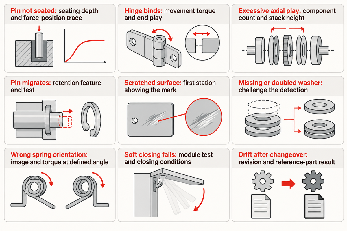
Use each symptom to choose evidence before choosing a correction. The entries are candidate causes to investigate; preserve the original recipe and affected parts while identifying the change.
| Symptom | Candidate station or input | Evidence to collect before action |
|---|---|---|
| Pin not seated | Pin presentation, guide or insertion reference | Pin length and seating depth in mm; force-position trace; burr condition |
| Hinge binds after retention | Support, alignment, forming depth or stack | Before/after movement torque in N·m; end play in mm |
| Excessive axial play | Washer presence or stack dimension | Component count, stack height and end play in mm |
| Pin migrates | Retention feature or designated interference zone | Feature dimensions; specified retention test in N; material/finish batch |
| Scratched surface | Feeder contact, nest or transfer path | First station showing the mark; contact location and debris |
| Missing or doubled washer | Singulation and presence inspection | Challenge parts; detection images; sensor response |
| Wrong spring orientation | Spring presentation and capture | Spring image before joining; torque at defined angle |
| Soft closing fails | Damper input, linkage or movement-test setup | Closing time in s; temperature, load and start angle; incoming module test |
| Drift after changeover | Recipe, fixture, tooling or measurement reference | Revision comparison; first-part dimensions and reference-part result |
Rosa E Hearn’s riveting-fault discussion in Design World identifies hole condition, burrs and tooling alignment among causes worth investigating. Examples using blind rivets require a discussion of fastener contexts. A solid hinge pin has no pull-mandrel to diagnose.
For covered US servicing, OSHA 29 CFR 1910.147 treats energy control separately from production stopping. Push buttons aren’t energy isolating devices. Clearing jams or adjusting tooling with exposure to unexpected movement or stored energy requires the site’s applicable energy-control procedure; trained authorized personnel must address residual energy and verify isolation. The minor-servicing exception has specific conditions and effective alternative protection requirements.
Changeover is complete when the approved setup produces accepted parts with the required checks active. Tool replacement alone doesn’t capture the full extent of the work required to bring the system back to that condition. Keep quality inspection and machine recovery evidence together. Evidence should be retained so that the next shift is able to identify a component change from equipment drift.
Frequently Asked Questions
Can one machine assemble both butt hinges and soft-close hinges?
Yes, when its tooling and tests cover both component families.
A shared base can support both when the fixtures, feeding equipment and joining stations accommodate the actual parts. The functional checks must also cover each joint. A simple butt hinge and a linked soft-close design can require substantially different sequences. Compare their bills of materials and changeover operations before choosing a shared cell; separate stations can be more practical when little tooling is common.
Does a hydraulic hinge assembly machine manufacture the damper?
Only when damper manufacture is included in the agreed scope.
A cell can install a purchased sealed damping module without manufacturing its cylinder, seals or internal fluid circuit. Another project can include those upstream operations. Identify the incoming module condition, its qualification and the connection made inside the hinge assembly cell. The final closing test then evaluates the assembled mechanism under its stated conditions. The word hydraulic alone doesn’t define the equipment boundary.
Are hinge assembly machines worth it?
They are worth considering when accepted output and quality gains justify total cost.
Compare first-pass good output, staffing, changeover losses, maintenance and tooling across the intended product mix. Joining control or repeatable inspection can address a measured constraint without automating every task. A lower-cost semi-automatic station can be sufficient when an operator loads difficult parts reliably and the machine controls the critical operation. Use the same observation period and accepted-product definition when comparing that option with a larger line.
What is a hinge machine?
It can mean component-making, hinge assembly or mounting-hole equipment.
Specify the incoming parts and required finished output. A furniture boring machine and a hinge component assembly cell perform different jobs.
Why is the hinge assembly machine not working?
Start with the displayed fault, affected variant and last successful operation.
Use the approved fault-recovery procedure to distinguish missing parts, orientation errors, fixture conditions and rejected test results. Preserve evidence before changing settings or attempting a fix.
Can a vision camera confirm hinge durability?
No. Vision checks selected visible features; durability needs product testing.
Validated vision systems can inspect presence, orientation or a measurable joint feature. They can’t establish long-term wear simply from an image. Product life also involves materials, joint geometry, loading and the relevant test conditions. Keep the evidence from an in-process image, a movement check and a longer product validation test distinct. Each supports a different release decision.
Key takeaway
Define the joint, control its assembly and test the finished behavior. The example comparison delivered 432 versus 436 accepted hinges/h despite a faster nominal cycle in the first cell.
Turn Your Hinge Drawing Into a Defined Assembly Task
Bring the component drawings, incoming part condition and required joint behavior to ZEUEE. Use the joint sheet to connect the technical conversation with the equipment scope.
The Perspective Behind This Guide
Cherry prepared this guide for ZEUEE to connect hinge joint design with assembly-machine scope. Public engineering and standards sources support the technical distinctions; the filled joint sheet and output calculations are teaching examples. No customer production result is claimed. The ZEUEE company introduction provides the business background for discussing a project.
Related Articles
References & Sources
- BHMA: A156.1-2025 Butts and Hinges, public Hardware Highlight
- Wang, Huang and Chang: Reliability-based tolerance redesign of mechanical assemblies, 2021
- Green and Kreul: Vibratory Feeder Bowl Analysis, 2009 abstract
- NIST: Assembly Performance Metrics and Test Methods
- John Sprovieri, ASSEMBLY: Force and Displacement Monitoring, 2026
- Doiron and Stoup, NIST: Uncertainty and Dimensional Calibrations, 1997
- NIST: Metrological Traceability Policy and Frequently Asked Questions
- Adam Cort, ASSEMBLY: Orbital and Radial Forming, 2002
- NIST/SEMATECH: What Is Acceptance Sampling?
- Jim Camillo, ASSEMBLY: Automating the Riveting Process, 2015
- Andrew Peterson, NIST: High-Mix/Low-Volume Collaborative Robots, 2020
- Theodore Doiron, NIST: Dimensional Measurement Uncertainty from Data, Part 2, 2016
- Rosa E Hearn, Design World: Typical Riveting Faults, 2024
- OSHA: 29 CFR 1910.147, Control of Hazardous Energy
WHY WE WRITE THIS
About ZEUEE Engineering Insights
ZEUEE shares technical guides based on real automation project experience. Since 2005, we have designed and manufactured non-standard automation equipment for connector assembly, wire harness production, robotic lines, vision inspection, and smart factory upgrades.
Founded in 2005
20,000 m² production base
120+ specialists
150+ R&D patents
ISO9001:2015 certified