Get in touch with Zeyu lntelligent Industrial Company

Turnkey Automation Systems: How Complete Lines Work

Turnkey Automation Systems deliver the equipment, controls, and integration required to complete an agreed manufacturing task. The useful question is whether the complete system can produce accepted parts consistently, including after a stop or product change.
By Cherry · Updated October 2026
Turnkey automation systems combine machines, tooling, controls and integration for a defined production task. Judge the delivered line by good output over an agreed operating window, with clear recovery and handover conditions.
Planning essentials
- Turnkey describes delivery responsibility; modular describes the equipment architecture. A project can be both.
- A passing part needs a matching identity, recipe and inspection record.
- An assumed 6 s cycle produces 441 good pieces/hour in the worked shift model, below its 450 pieces/hour requirement.
- Simple payback measures cost recovery. Project approval also needs demand, ramp-up and cash-flow assumptions.
The broader production line automation overview explains automation types and rollout. In this context, the point is to analyze the behavior of a delivered project: what happens to a part, what the controller decides, and what production result the factory can really use.
What Makes an Automation System Turnkey?

In a turnkey industrial automation project, the integrator is responsible for delivering an agreed-upon operating result within a defined scope. The package may contain off-the-shelf equipment, custom-built systems or both. Turnkey describes that kind of delivery arrangement. It may not describe a particular machine type, level of automation or a standard duration of factory installation.
End-to-end industrial automation sets boundaries: incoming parts and their conditions, finished assemblies, acceptance tests, and interfaces with other parts of the factory. A complete turnkey package should identify the tooling, software and on-site work within those boundaries. Material preparation, utility connections and operator assignments also need an owner.
Coordinated system design and fewer unowned interfaces yield key benefits of turnkey automation solutions. Those benefits disappear if the supplier tests one part variant while the factory expects another, or if a downstream packing operation sits outside the agreed scope. A ready-to-use automation offer remains scoped to a particular application.
ZEUEE’s turnkey automation systems solution page describes its commercial integration offering. On the technical side, similar challenges exist. OSHA’s guide on industrial robot systems covers tooling, controls, sensors and communication interfaces in a robotic system. Robot arms don’t cover all of those areas.
What Makes a Robot Solution Turnkey?
A combination of an arm with the application equipment and the integration to perform a task is called a turnkey robot. That normally includes end-of-arm tooling, part presentation, controls and an operator interface. A pre-engineered cell may require less engineering work, but the provided application has to conform to the workpiece, surrounding equipment, and the operation conditions.
For machine tending, the end result is a correctly loaded machine and the controlled return of a finished part. For palletizing solutions, it’s the specified load pattern and the product’s handling. The results can’t be attributed to the robots’ payload rating alone. Buyers retain responsibility for operating the equipment under the agreed conditions and maintaining the application after handover.
How the Mechanical, Control and Data Layers Work Together
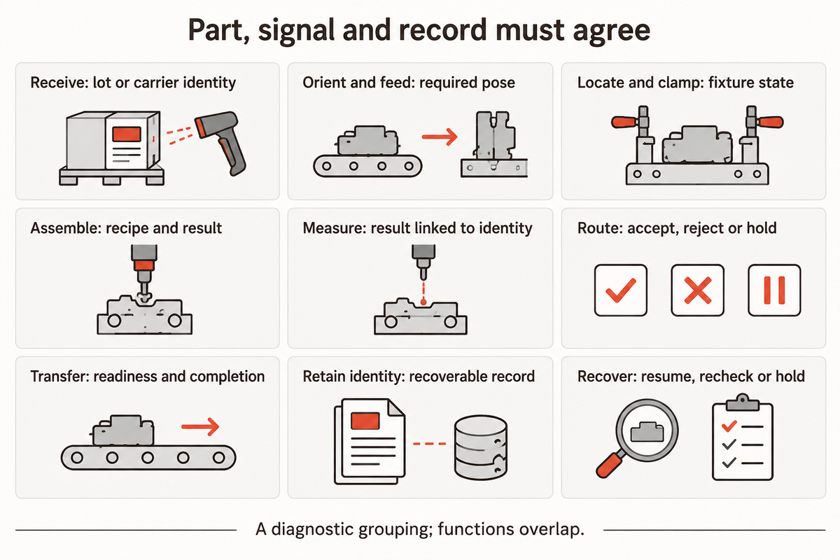
An integrated and properly designed automated assembly system must keep physical movement and control state, as well as production records, consistent. A fixture holds the part, a controller authorizes the next action and a record indicates the result. A mismatch between those layers can leave a mechanically completed assembly without a usable inspection or traceability result.
Control systems use programmable logic controllers (PLCs) to sequence equipment and exchange readiness information. Material handling systems move the work between stations. Inspection systems determine whether measured features meet the configured criteria. SCADA systems can collect supervisory information, but a screen showing a pass does not by itself identify which physical part passed.
NIST’s manufacturing-services research, in the right context, distinguishes interpreting a message from achieving the right consequence when services interact. It is a way to examine a line, rather than a prescribed nine-step production sequence.
9-Function Part-Signal-Decision Map
The 9-Function Part-Signal-Decision Map connects each physical function to its control decision and retained production evidence.
| Function | Physical condition | Signal or decision | Retained evidence |
|---|---|---|---|
| Receive | Correct part family reaches the line | Accept the selected family and route | Lot or carrier identity |
| Orient and feed | Part is presented in the required pose | Presentation condition permits pickup | Feed exception and variant |
| Locate and clamp | Part occupies the intended nest | Position and fixture state permit the process | Nest and fixture version |
| Assemble | Joining or insertion is completed | Process completion meets the configured conditions | Recipe version and process result |
| Measure | Feature or function is tested | Apply the correct acceptance criteria | Measurement linked to part identity |
| Route | Accepted and rejected work separate | Disposition follows the recorded result | Accepted, rejected or held status |
| Transfer | Receiving station can take the work | Readiness and completion meanings agree | Transfer confirmation and event time |
| Retain identity | Work remains associated with its carrier or identifier | Match part, recipe and result | Recoverable production record |
| Recover | Interrupted work has a known condition | Resume, recheck or hold under the approved procedure | Interruption and final disposition |
These functions overlap. Identity must be preserved while the part is being moved. Recovery can involve many stations. Controls and automation engineering therefore need shared meanings for signals such as part-ready and cycle-complete. PLC programming can’t define an unclear interface by adding more messages.
EXAMPLE: There’s a connector line with 12 indexed carriers. A part passes an electrical test, but the controller restarts before the result is committed against its carrier identity. The part is still physically present, but the record is uncertain. Restarting the motion sequence leaves quality with no reliable disposition. The system integration task is to preserve or reconstruct the association, then hold or recheck unresolved work under the approved recovery procedure. Testing and inspection need a defined record boundary as well as a measurement boundary.
ZEUEE’s DC wire production line focuses on the product-specific nature of assembly and testing. The same mapping technique can be applied without transferring that machine’s published specifications to a different product family.
Can You Integrate Automation With Existing Machines?
Existing equipment can be integrated when its mechanical handoff, controls interfaces and operating conditions support the proposed task. The integration work must define how each machine receives work, reports its state and handles an interruption. The integration work must be defined to address communication protocols, and physical and process boundaries, as well.
Assessing changes in function or control strategies requires a more complete evaluation than connecting data. For a UK project, HSE’s modified-machinery guidance distinguishes substantial changes from like-for-like refurbishment and addresses modified or affected systems. That particular example shouldn’t serve as a global reevaluation rule.
Which Automation Architecture Fits the Process?
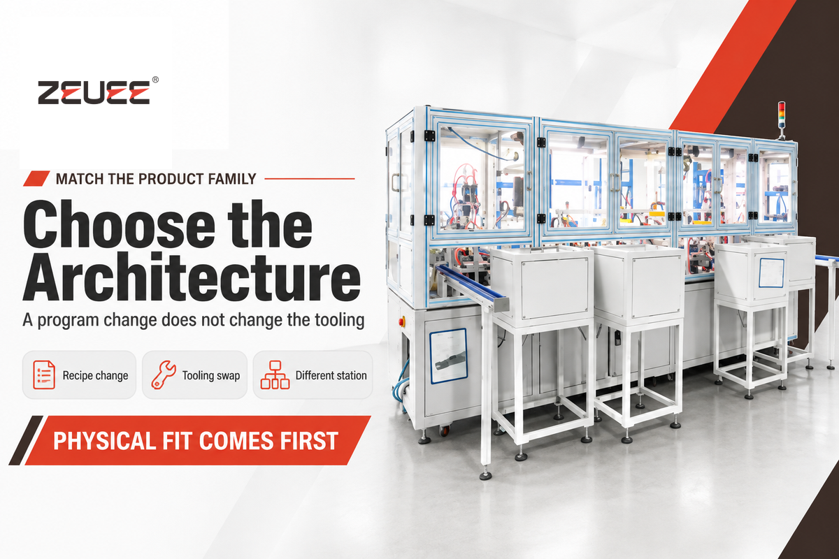
Turnkey systems can use dedicated equipment, programmable cells, modular stations, or a combination of automated and manual work. Useful comparisons include variants, changes in product routing and the presentation of materials. A custom solution and a modular structure can both form part of a turnkey delivery; they are not competing contract models.
Industrial automation solutions need process development before architecture selection. A robot can change its motion program; however, its feeder and fixture may still only accept a single geometry. Integrators can customize tooling, but custom automation still depends on reliable part presentation. A complete automation proposal has to show what product changes require a recipe change, a tooling swap or a different physical station.
The study by Herps and colleagues on high-mix manufacturing places buffers and material handling as design decisions that can be integrated together. It includes a hybrid architecture of local and shared buffers and different types of handling equipment. It isn’t the case that all combinations of humans and robots are economical.
Consider a family of three connector variants with two variants in the same nest and feeder system. The third variant is different in terms of the inspection recipe and orientation. Programming all three part numbers in the controller doesn’t make the variants mechanically interchangeable. Engineering can compare a dedicated third station with a planned tooling change, including the resulting lost production time. Operations must have the variant mix to perform this analysis. Finance needs the cost of different versions to evaluate which option to select based on a given demand assumption. The automation needs are defined by the flow of the family rather than preference of a particular robot.
A different hinge assembly machine addresses a different part geometry and joining sequence. Using automation technology across industrial products still requires application specific tools and acceptance criteria.
What Are the Four Types of Automation?
Fixed, programmable, flexible, and integrated automation are useful comparison labels, but describe different things. Fixed equipment repeats a defined sequence; programmable equipment changes its sequence through a program; flexible systems support switching within a defined family. Integration is the relationship of equipment and information to one another. A fully integrated line can therefore also be fixed or flexible.
For a turnkey project, evaluate the physical architecture of systems separately from the delivery promise. Pre-engineered machine tending or palletizing cells address defined tasks. Complex automation involving several assembly processes needs the same clarity about incoming material, retained records and interfaces.
How to Define Throughput Without Hiding Production Losses
Good output over an elapsed shift is a combination of productive time, cycle time, and yield. A nominal machine rate removes time lost before and between cycles. Define the acceptance boundary and the time window first, then assign each lost minute once. Otherwise, two apparently similar claims to output may measure different things.
The NIST-hosted research on manufacturing performance indicators distinguishes machine effectiveness, setup-time treatment, and line throughput. The line-level focus includes operations and buffers as well as their interactions. An overall equipment effectiveness percentage only helps compare when underlying time definitions agree.
8-Hour Run-State Loss Map
Losses in an 8-hour run state are modeled as mutually exclusive time states, and an accepted output over the whole shift is calculated.
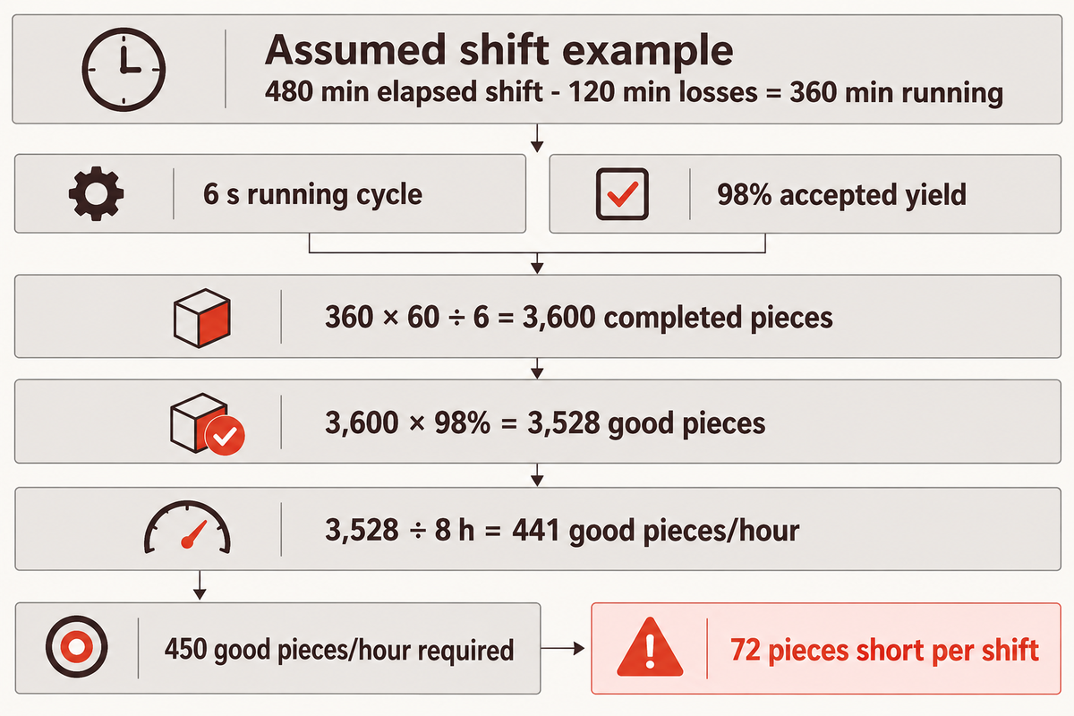
Assumed inputs: one 480 min shift, a 6 s running cycle and 98% accepted yield. The following filled ledger removes time losses once.
| State or subtotal | Time | How it enters the calculation |
|---|---|---|
| Elapsed shift | 480 min | The reporting denominator |
| Breaks | 30 min | Subtract once |
| Changeover | 20 min | Subtract once |
| Faults | 25 min | Subtract once |
| Starved: no incoming work | 15 min | Subtract once |
| Blocked: no downstream space | 10 min | Subtract once |
| Microstops | 20 min | Subtract once; exclude from running-cycle measurement |
| Total time losses | 120 min | Sum of the six loss states |
| Running time | 360 min | 480 min minus 120 min; a subtotal |
The arithmetic is 360 min × 60 s/min ÷ 6 s/piece = 3,600 completed pieces. Applying 98% yield once gives 3,528 good pieces. Dividing by the full 8 hours gives 441 good pieces/hour. A requirement of 450 good pieces/hour needs 3,600 accepted pieces per shift, so this case falls short by 72 pieces.
That shortfall changes the decision. Engineering needs to remove a real constraint or optimize the process. Operations can’t approve the line merely because its running rate is 600 pieces per hour. A faster robot also will not solve time spent waiting for incoming parts or downstream capacity unless that change addresses the cause.
To analyze downtime, distinguish the state you observed from the cause you identified. A feeder fault may starve several downstream stations. Each station may report waiting, but those reports shouldn’t become several losses on the same line-level minute. Microstops that have already been removed from running time shouldn’t be charged against performance. Doing so will understate output.
Key takeaway
The worked line runs at a nominal 600 pieces/hour but delivers 441 good pieces/hour over its 8-hour shift. Capacity approval belongs at the agreed acceptance boundary and elapsed-time denominator.
What the Investment Model Must Count
A good automation cost model separates installed capital from the annual cash effects a business can realize. The cost of equipment is just one input. Site work, internal engineering and ramp-up belong in the starting cost; recurring energy, maintenance and production losses affect the annual benefit. Labor reassignment alone doesn’t guarantee cash savings.
The U.S. Government Accountability Office cost guide ties estimates to scope, technical assumptions and sensitivity analysis. For manufacturing automation, that means comparing complete options against the same business needs, product mix and required good output.
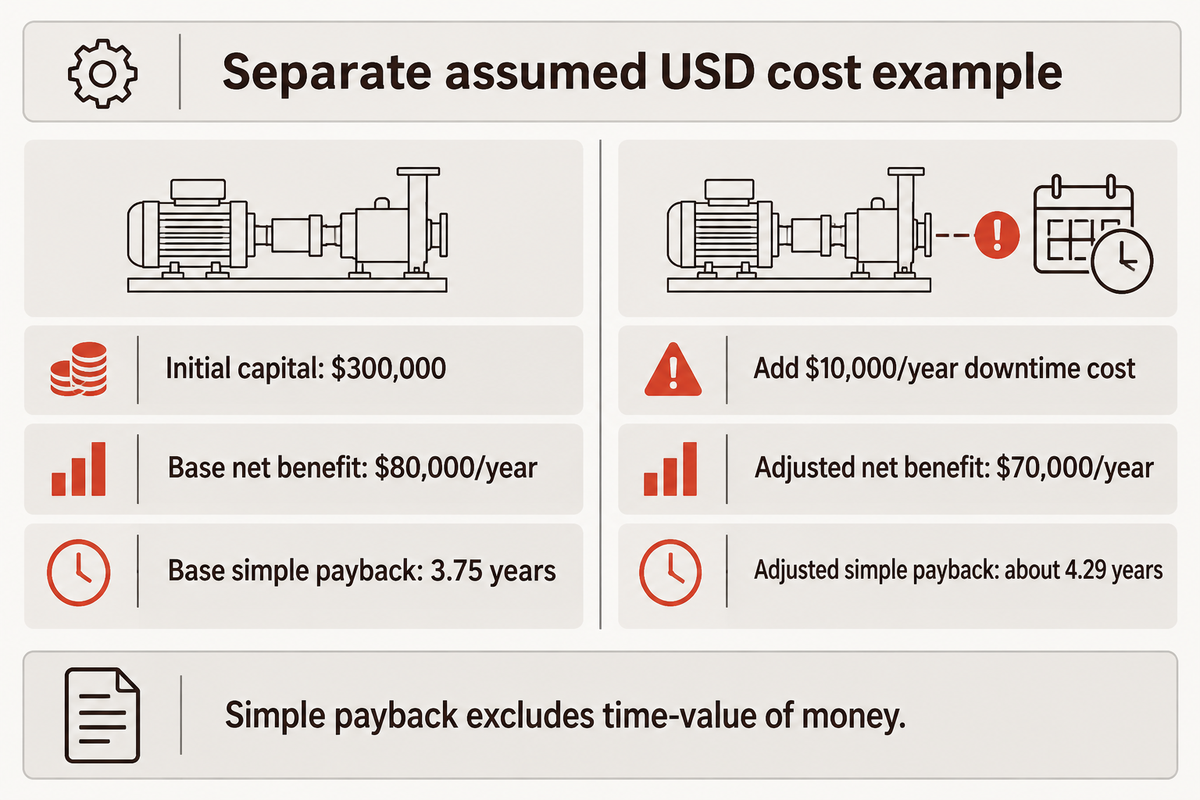
Separate cost example, assumed USD inputs: $240,000 equipment + $24,000 site work + $16,000 internal engineering + $20,000 training and ramp-up = $300,000 initial capital. Assume $75,000/year of realized labor or overtime savings and $18,000/year less scrap. Extra energy of $4,000/year and maintenance of $9,000/year reduce the net benefit to $80,000/year.
5-year cost boundary: base case and downtime sensitivity
| Cost item | Base assumption | Downtime sensitivity |
|---|---|---|
| Purchase price | $240,000 | $240,000 |
| Installation & commissioning, including internal work and ramp-up | $60,000 | $60,000 |
| Energy, 5 years | $20,000 | $20,000 |
| Maintenance & spares, 5 years | $45,000 | $45,000 |
| Additional downtime cost, 5 years | $0, explicitly assumed | $50,000 |
The five-year cost totals are $365,000 and $415,000. Base simple payback is $300,000 ÷ $80,000/year = 3.75 years, or 45 months. Adding $10,000/year of downtime cost lowers net benefit to $70,000/year and extends simple payback to about 4.29 years.
The base case assumes no additional downtime cost. The sensitivity case evaluates this assumption. A factory that keeps all employees on the same paid hours must replace the labor saving input with its actual overtime, vacancy or output effect. The same effect can double-count benefits: adding saved labor and increased revenue.
NIST’s Smart Investment Tool includes net present value and internal rate of return as well as payback and sensitivity analysis. Simple payback doesn’t take into account the time-value of money. The turnkey automation payback calculator can be useful for organizing project inputs, but the factory’s demand and cash flow assumptions will still need to be analyzed for project approval.
A 3.75-year payback in the assumed case becomes about 4.29 years after adding $10,000/year of downtime cost. If the shortfall in the separate capacity case requires extra staffing or overtime, the annual benefit must also be adjusted. Industrial automation can reduce costs only if the modeled effects occur in the operating plan.
How a Turnkey Project Reaches Stable Production
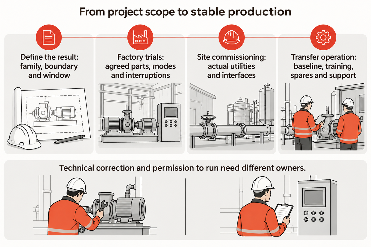
Producing stable and reliable products requires management of the turnkey process beyond successful demonstration. The turnkey process must connect agreed requirements, factory testing, site installation and operator-run production. Each phase must show the conditions used, the constraints remaining and evidence needed for making the next decision. Production release and delivery are distinct milestones.
Automation projects start with a defined product family and process result. Turnkey solutions are designed around those requirements, then built and tested. Factory trials should exercise the agreed variants and operating modes. Site work connects the actual utilities and machine interfaces. This is why the two test environments can’t be treated as the same.
“These tests should be performed by the integrator and verified by the user.”
Simulation and other automation tools can identify problems with interface and/or sequence prior to deployment. Automation World’s virtual-commissioning feature describes models driven by controller logic. The modeled conditions still need to match the built equipment and actual workpieces; animation alone is not a production trial.
- Define the result. Set the product family, acceptance boundary and reporting window.
- Prove the integrated sequence. Exercise the agreed parts, modes and interruption cases in factory trials.
- Commission at the site. Test actual utilities, interfaces and installation conditions before production startup.
- Transfer operation. Hand over the approved software baseline, training, spares information and support arrangements.
Technical correction and permission to run also need different owners. A 2026 Automation World analysis of stalled startups describes how working machines can wait for unresolved cross-team decisions. A vision supplier may correct a reading defect while quality needs to decide on the work that’s affected.
Before operators deploy a new recipe, the release should identify its approved products and current restrictions. Technical support must use the same versions of software and as-built drawings. A technician trying to troubleshoot from an outdated backup can undo a correction already made on the line. Recovery training therefore needs the production baseline, rather than a collection of unrelated files.
The comparison of turnkey automation manufacturers covers supplier choice. For a chosen project, the practical handover question is whether the plant can run the agreed work and identify who resolves a technical issue and who authorizes production while it remains open.
Industry Outlook: What Is Changing in Connected Automation?
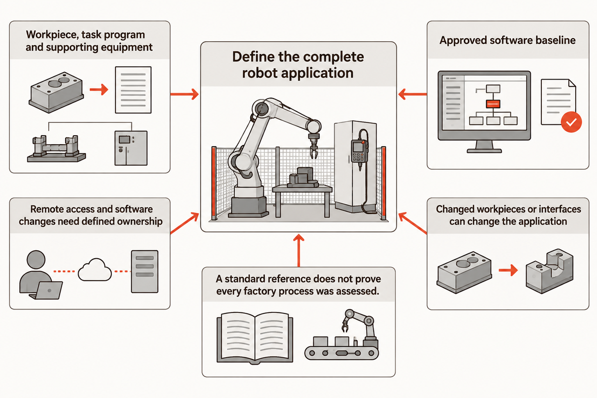
Integration specifications of robots must describe the entire application, including the workpiece, task program and other equipment. The 2025 revision of ISO 10218-2 makes that application boundary a useful planning focus. A robot selected to perform a task must be integrated and assessed in the way the factory will use it.
The ISO 10218-2:2025 record identifies Edition 2, published in February 2025, and lists the 2011 edition as withdrawn. Part 2 addresses industrial robot applications and cells, including integration and commissioning. It complements the robot-manufacturer focus of Part 1; naming one standard does not establish that every process in a factory has been assessed.
The Association for Advancing Automation’s Revision Explanation states incorporated collaborative-application requirements, clearer functional requirements, and added cybersecurity requirements regarding the safety of industrial robots. The association clarifies the focus on a collaborative application, rather than considering the robot label in isolation as the solution.
For a connected system, this relates the engineering specification to change control. A new task program, a modified workpiece, or an altered interface can all change the application being considered. Remote access, as well as software changes, need defined ownership and a controlled release. More connectivity provides more ways to exchange information, while also making the boundary between the line and external systems worth specifying.
Upon specification for a project using the 2025 edition, the intended application, assessment and validation deliverables should be stated. The scope of the work should include the end effector and surrounding machinery, including the robot arm. This allows engineering, operations and the integrator to evaluate a common application, prior to building the equipment.
Frequently Asked Questions
How long does a turnkey automation project take?
Project duration needs separate engineering, equipment-build, factory-test and site-commissioning milestones.
A delivery date alone leaves the production-start question unanswered. A useful schedule identifies when the product and process requirements freeze, when representative parts are available, and which site conditions must be ready. Custom-built equipment and a pre-engineered cell can require different amounts of application work. Tie each milestone to its completion evidence and named owner.
Which industries benefit from turnkey automation?
Factories benefit from turnkey automation when a defined production task needs coordinated equipment, controls and testing.
Automotive components and electronics assembly provide familiar examples, but the industry name alone does not establish a good project. Product variation, presentation, inspection and demand determine the scope. A supplier’s experience in one process does not transfer every capability to another. Compare the proposed application with the actual product family and the factory’s required output.
Is turnkey production the same as contract manufacturing?
Turnkey equipment delivery and contract manufacturing describe different purchases.
In an equipment project, the integrator delivers a system that the buying factory will operate. A contract manufacturer supplies production services or finished goods under an agreed arrangement. The word turnkey can appear in either offer, so identify the deliverable first. Equipment ownership, operating responsibility, material supply and acceptance should follow that defined transaction.
Does turnkey automation remove every manual task?
A turnkey line can include manual loading, replenishment or inspection tasks.
The agreed process boundary determines the work included. Manual labor may remain at material preparation, packaging or product changeover. Staffing and task timing need to appear in the output model, rather than being inferred from the turnkey label.
Who should own the PLC program and backups?
The contract should define software ownership and the plant’s usable backup, access and licensing deliverables.
Ownership and recovery access are different questions. A factory needs the agreed files, versions and permissions to restore the delivered application or obtain support. The handover should identify controller and interface backups, applicable software licenses, recipe files and the as-built release. A filename without a known version or a restore procedure provides little help during a stoppage. Keep subsequent approved changes connected to that baseline so maintenance and the integrator troubleshoot the same system.
Which automation platforms can a turnkey system support?
Platform compatibility follows the selected controllers, interfaces and integration scope.
A shared protocol does not settle message meaning, software versions or support access. Include existing equipment and plant data interfaces in the system boundary. The delivered solution needs to support the intended task, rather than only exchange a connection signal.
What should operators learn before handover?
Operators need task-specific training in normal operation, product changes, alarms and approved recovery.
Training should use the delivered product family and current software release. Operators need to recognize accepted, rejected and unresolved work, understand when production must be held, and know who authorizes the next action. Maintenance staff need the relevant fault information and backup baseline. A demonstration with the integrator making every adjustment does not show that the plant can run independently. Include the people who will operate the line across shifts, together with the responsibilities they actually hold.
Turn a capacity target into a defined project
Start with the product family, required good pieces per shift and known loss states. Add the acceptance result and the interfaces the line must preserve. That gives a project discussion a concrete operating target before equipment selection.
About this systems guide
Cherry prepared this guide for ZEUEE, whose public offering includes assembly automation and testing equipment. The technical discussion draws on the linked public engineering sources. The part-signal map is an original synthesis; the shift and cost examples use stated assumptions to explain the calculations and their decision boundaries.
Related reading
References & Sources
- Industrial Robot Systems and Industrial Robot System Safety — U.S. Occupational Safety and Health Administration, Technical Manual IV.4.
- Service-Oriented Architectures for Smart Manufacturing Project — National Institute of Standards and Technology.
- Refurbished and modified machinery — UK Health and Safety Executive.
- A simulation-based approach to design an automated high-mix low-volume manufacturing system — Herps and colleagues, Journal of Manufacturing Systems, 2022.
- A Hierarchical Structure of Key Performance Indicators for Operation Management and Continuous Improvement in Production Systems — NIST-hosted research paper.
- Cost Estimating and Assessment Guide — U.S. Government Accountability Office, 2020.
- Smart Investment Tool — National Institute of Standards and Technology.
- Digital Twin Makes Virtual Commissioning a Reality — Automation World, 2019.
- Why Manufacturing Automation Startups Stall — Muhammad Rafay Ikram, Automation World, 2026.
- ISO 10218-2:2025 — International Organization for Standardization, official scope and publication record.
- Updated ISO 10218: Answers to Frequently Asked Questions — Association for Advancing Automation, 2025.
WHY WE WRITE THIS
About ZEUEE Engineering Insights
ZEUEE shares technical guides based on real automation project experience. Since 2005, we have designed and manufactured non-standard automation equipment for connector assembly, wire harness production, robotic lines, vision inspection, and smart factory upgrades.
Founded in 2005
20,000 m² production base
120+ specialists
150+ R&D patents
ISO9001:2015 certified