Get in touch with Zeyu lntelligent Industrial Company

HYPCON Contacts Machine: Process, Selection and Acceptance Guide

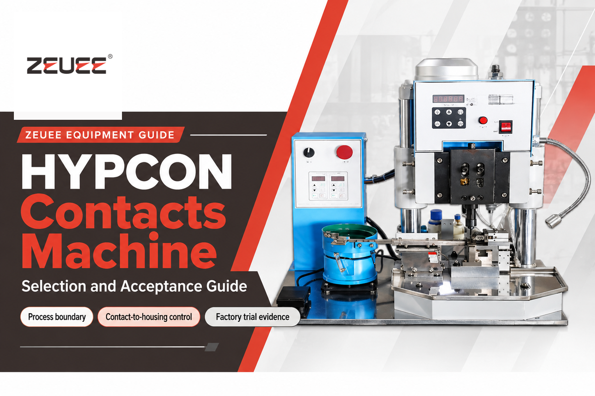
A HYPCON Contacts Machine is a controlled connector assembly station that evaluates the full contact-to-housing process. Evaluation shouldn’t be limited to assessment of the contact insertion motion. The contacts machine should position the desired contact in the proper housing cavity and reach the correct seated position. The contacts machine should provide evidence the assembled housing is acceptable for further processing. Requirements for assessment of contact housings machined by the contacts machine vary with contact and housing geometry, wire preparation, variant mix, and inspection method.
This document outlines a process for evaluating HYPCON contacts machines prior to purchasing or integrating them in a production line. It outlines the process steps and risks associated with various interfaces, architecture choices, acceptance evidence, changeover and maintenance. The existing HYPCON Contacts Machine solution page describes how to configure a HYPCON Contacts Machine. This document is for the questions that help in describing that configuration.
What does a HYPCON Contacts Machine do?
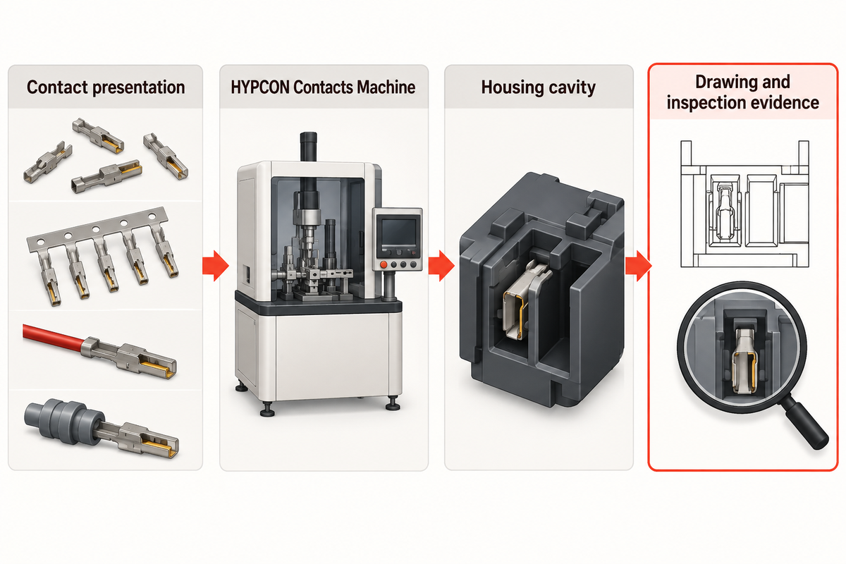
In a connector assembly line, a contacts machine handles a defined family of conductive contacts, and places them in corresponding insulating housings or subassemblies. Use IEC 60512 for test-method context. Depending on the product, the incoming contact may be presented loose, carrier-fed, crimped to a wire, or sealed. The output of the contacts machine is an assembly which must be in accordance to the drawing, and meet the inspection requirements, of that specific contact and cavity.
It’s important to define that boundary because various operations including contact, wire crimping and insertion, and electrical testing are related but distinct operations. A quotation should identify which of these operations are performed by the HYPCON station and which are performed by upstream and downstream operations. The quotation should also identify if the machine merely inserts the contact or if it confirms the position, retention, and presence, and rejects contacts if not acceptable.
Start with an input/output sketch. Include the contact, the housing datum, the insertion axis, final seated position and anything else that goes with the contact. Add part numbers and drawing revisions. A simple sketch often reveals that a proposed machine is being asked to handle two different presentations or to prove a quality characteristic that its sensors may not be able to observe.
Map the contact-to-housing assembly sequence
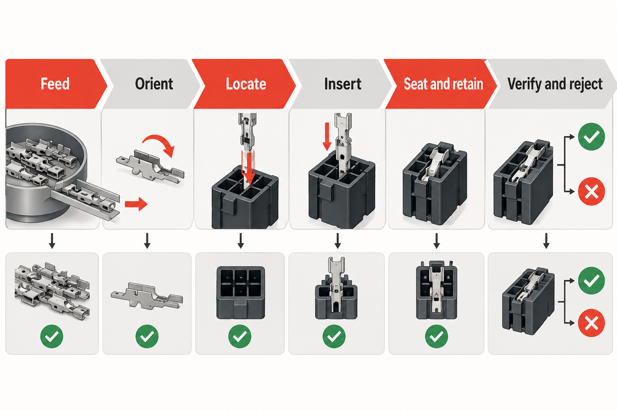
Break the machine cycle into observable stages. See TE Connectivity connector system application context for product-interface context. The information below gives engineering, production and quality teams a common language for a trial.
| Stage | What the machine must control | Evidence to define |
|---|---|---|
| Feed | Supply the correct contact in a stable presentation. | Part identity, supply format and feeder recovery behavior. |
| Orient | Present the contact with its functional and locking features aligned. | Orientation check and wrong-way challenge response. |
| Locate | Hold the housing against a repeatable datum. | Nest drawing, cavity assignment and support points. |
| Insert | Move the contact along the specified axis without damaging the part. | Tool path, contact zones and process limits. |
| Seat and retain | Reach the required position and engage the applicable retention feature. | Position, lock-state or retention check defined by the product specification. |
| Verify and reject | Separate accepted assemblies from detected defects. | Inspection recipe, reject reason and traceability record. |
A completed motion doesn’t guarantee a completed assembly. A contact may be present, but may not be in the final position. A contact can be present but off-position, or it can appear seated while a lance or secondary lock remains disengaged. The acceptance plan should name the feature that proves each required condition.
Match machine architecture to production reality
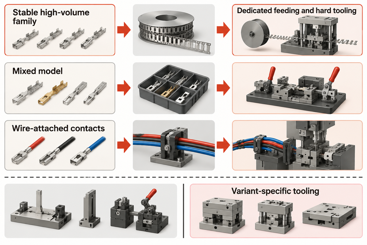
Machine architecture should follow the production problem. Compare the tooling context with Molex application tooling overview before fixing the machine boundary. A high-volume, stable part family may justify dedicated feeding and hard tooling. A mixed model may require quick-change guides and clear first-off instructions. A line that handles wire-attached contacts may need support and routing for the wire rather than the same transfer path used for loose contacts.
Which production facts should drive the choice?
- Variant mix: list contact, housing and preparation variants separately; similar names do not prove compatibility.
- Demand pattern: state target output, batch size, shifts and the acceptable recovery time after a feeder stop.
- Changeover: identify which feeders, nests, guides, grippers and recipes change, and how the first-off sample is approved.
- Inspection: decide whether presence, orientation, seating, retention or electrical checks are in-cycle, sampled or downstream.
- Data: define the recipe revision, reject reason, sample identity and retention period for records.
A modular machine base may reduce duplication of controls, but the reusable base should be separated from variant-specific tooling in the quotation. This prevents low-cost, off-the-shelf machines from requiring additional trial work and resulting additional nests and feeders.
Check the interfaces that cause quality failures
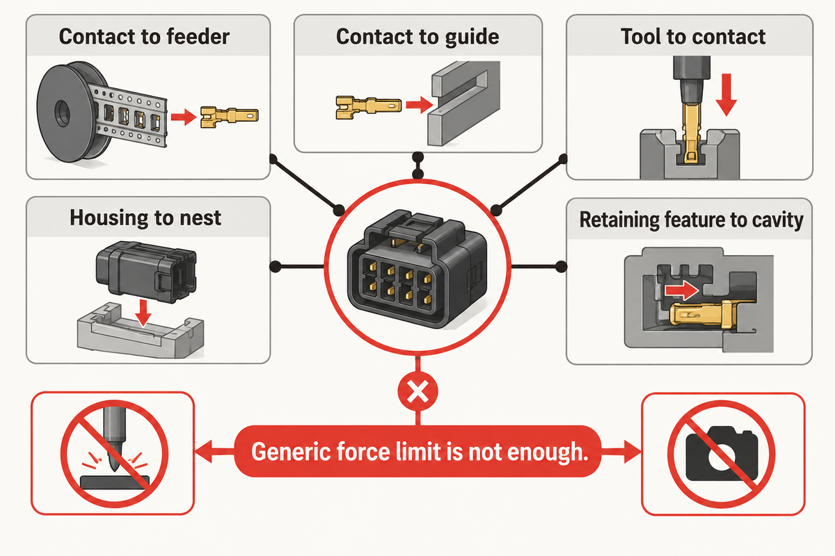
The most difficult failures happen at an interface: contact to feeder, contact to guide, tool to contact, housing to nest or retaining feature to cavity. See IEC 60512 connector test methods when selecting the applicable check. Review these interfaces before discussing cycle time.
| Interface | Typical question | Useful review evidence |
|---|---|---|
| Contact and feeder | Can plating, burrs or carrier variation create bridging or misfeeds? | Feeder trial with representative lots and recovery observations. |
| Contact and guide | Which surfaces may be touched, and where is the contact supported? | Annotated tool-contact map and post-cycle surface inspection. |
| Housing and nest | What datum locates the cavity, and how is housing movement prevented? | Nest drawing, cavity challenge and position check. |
| Contact and cavity | How is the insertion axis maintained through the lead-in? | Alignment review, seating evidence and damaged-part analysis. |
| Retention feature | How is engagement confirmed rather than inferred from presence? | Connector-specific lock or retention method and sample records. |
| Reject path | Can an incorrect or incomplete assembly escape the station? | Known-defect challenge, reject confirmation and disposition record. |
For these checks use the actual contact and housing drawings. The IEC connector requirements and tests are a useful reference point for identifying the applicable connector test family. A camera image from another connector family or a generic force limit cannot ensure correct setup of a HYPCON. Use the IEC 60512 standard, for example, and describe the test method and revision instead of naming the standard and using it as a universal machine setting.
Build a practical acceptance plan with the 9-Point Contact-to-Housing Acceptance Matrix
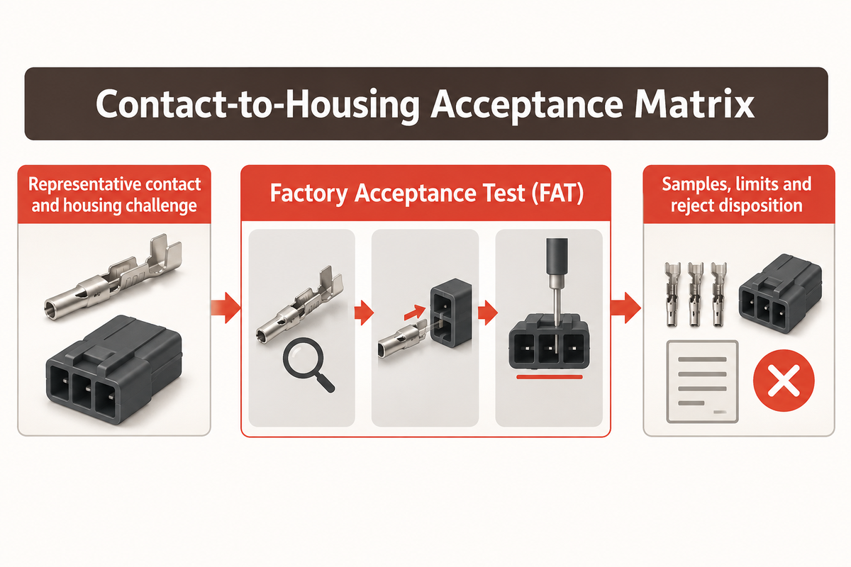
The Contact-to-Housing Acceptance Matrix in the Factory Acceptance Test (FAT) should prove the defined scope including tractable artifacts and challenges. The applicable check should be tied to the product evidence described in IEC 60512 connector test methods. The plan may be brief, but every requirement must be verifiable.
| Acceptance category | Sample or challenge | Record to retain |
|---|---|---|
| Feed | Representative contact presentation. | Part identity, supply format and recovery observation. |
| Orient | Correct and reversed presentation. | Orientation check and response. |
| Locate | Housing datum and cavity location. | Nest reference and position check. |
| Insert | Insertion along the defined axis. | Tool path and damage check. |
| Seat | Position at the agreed seating limit. | Depth or position result. |
| Retain | Product-specific retention challenge. | Retention method, sample identity and result. |
| Verify | Normal run and known defect. | Inspection result and acceptance limit. |
| Reject | Wrong or incomplete assembly. | Reject code, recovery action and retained evidence. |
| Traceability | Good and intentionally rejected samples. | Recipe, variant, operator and sample record. |
| Acceptance block | Sample or challenge | Record to retain |
|---|---|---|
| Normal production run | Representative contact, housing and preparation. | Recipe revision, run quantity, cycle observations and sample IDs. |
| Wrong orientation | Controlled reversed or mismatched presentation. | Expected detection, actual response and reject disposition. |
| Seating condition | Parts at the agreed position limits or a documented challenge. | Measurement method, limits and results. |
| Retention condition | Assembly checked with the product-specific retention method. | Test setup, load or criterion, sample identity and result. |
| Changeover | At least the agreed production variants. | Change-part list, setup time, first-off approval and recipe lock. |
| Traceability and rejects | Good and intentionally rejected samples. | Reject code, data record, recovery action and retained evidence. |
Almost all challenges can be resolved. Agree who owns samples, tools, images, recipes and findings prior to the trial. A successful sample means one configuration worked with the given conditions. It doesn’t prove that every similar looking configuration works as well.
Plan changeovers, maintenance and traceability
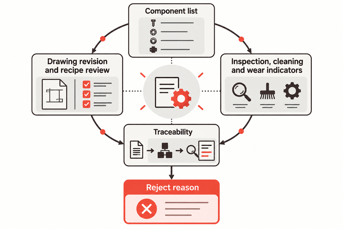
Maintain the quality of the interfaces. Keep the maintenance boundary aligned with the machine scope described on the HYPCON Contacts Machine solution page. Create and maintain a component list of feeders, guides, nests, sensors and contact tools. For each component, document inspection points, cleaning methods, wear indicators, spare parts and changes. The same list can be used for planned maintenance and to support troubleshooting.
Changes of tools and dies to support a recipe change require a review; the recipe name alone is insufficient. First, obtain approval of the drawing revision and store it with the machine setup record. Keep the governing ISO standards reference with the same controlled record when the acceptance scope cites a management or quality requirement.
Traceability should connect a finished assembly to the recipe, variant, operator or station identity, inspection result and reject reason required by the customer. The particular data elements depend upon the product and contract. Define them before commissioning to prevent the machine from producing records that don’t support a subsequent investigation.
Troubleshoot defects without masking the cause
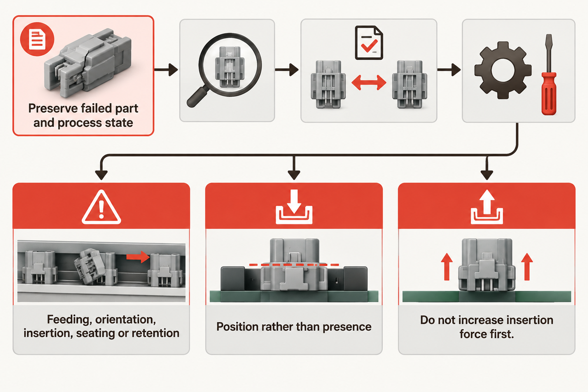
When a failure occurs, isolate and preserve the affected part and the state of the process. Use the relevant product-interface context from TE Connectivity connector system application context when tracing the cause. First identify where the failure condition occurred (i.e. feeding, part orientation, insertion, seating, retention or part inspection). Next, evaluate the incoming part and tooling contact, housing datum and recipe revision.
What should be checked when contacts bridge or misfeed?
Consider the supply format, contact variation, feeder track, escapement timing and recovery behavior. Confirm the contact is the approved revision and guides are clean and intact. A faster feeder setting can disguise the variation and affect a greater number of parts.
What if the contact is present but not fully seated?
Consider cavity location, lead-in condition, alignment, and the presence of wire and seal interference. Also, confirm that the inspection method measures the position rather than just determining the presence of metal. Retain a failed sample and compare it with an acceptable sample under the same inspection view.
What if a retained contact later backs out?
Verify the retaining feature and the validated retention method. Review whether a secondary lock was installed and whether the housing revision is correct. Also consider whether the machine can detect an incomplete lock state. Don’t increase insertion force until the interface and the acceptance criterion are understood.
Prepare a quotation and factory trial brief
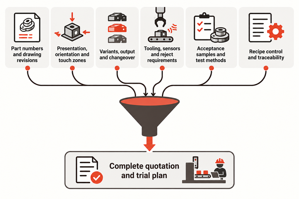
A good brief lets a supplier quote the complete work. Include:
- contact, housing, wire and seal part numbers with drawing revisions;
- incoming presentation, orientation and approved touch zones;
- target variants, output, batch pattern and changeover expectations;
- tooling, nests, feeders, sensors, inspection and reject requirements;
- acceptance samples, challenge parts and the applicable test methods;
- recipe control, traceability fields, maintenance documents and training;
- Define what the supplier will demonstrate, deliver and support after installation.
Use this brief to compare offers to configure a HYPCON Contacts Machine. For company background see the ZEUEE About Us page. Contact us if you want to talk about your actual contacts, housings and samples using the contact form.
FAQ
What is a HYPCON Contacts Machine used for?
A HYPCON Contacts Machine is used to process electrical contact assemblies. See IEC 60512 connector test methods for the applicable test-method context. Scope depends on contact and housing, presentation, retention features, wire preparation, acceptance evidence, variant mix, and records showing each permitted combination was evaluated. The buyer should validate the quoted station against the required variants, functions and trial records, then retain the configuration, checks, samples and limits that the trial actually covered.
Can one machine handle multiple contact variants?
Yes, when the platform, changes, feeders, guides and recipes are designed for the full variant set; similar contact names and dimensions alone are not sufficient. Consider the permitted tool-contact surfaces, housing datum, insertion direction, wire preparation and acceptance checks for each variant. Require a trial record for every configuration that the quote purports to cover.
What should a buyer verify during acceptance?
Verify the normal run, wrong-orientation challenge, seating evidence, retention method, changeover, reject handling and traceability records. Representative parts should be kept with results and sample identities should be retained. Acceptance should state what each check proves and which product document defines the limit, rather than relying only on cycle completion or a general force reading.
How should maintenance records be structured?
Maintain the feeder, guide, nest, sensor and contact tooling registers tied to inspection points, cleaning instructions and wear indicators, as well as spare parts and change history. Record the recipe and drawing revision used after maintenance. That record helps distinguish a worn interface from a material or setup change when a defect occurs.
What information should be sent for a quotation?
Send contact and housing part numbers, current drawings, sample parts, incoming presentation, target variants, expected output, changeover needs and acceptance requirements. Provide wire, seals or carriers that are in the condition as they appear when they leave the station. An annotated contact-to-cavity sketch helps the supplier identify tooling assumptions before proposing a configuration.
References & Sources
- ZEUEE HYPCON Contacts Machine solution page.
- ZEUEE company information.
- IEC 60512 connector test methods, consult the applicable method and edition for the product specification.
- TE Connectivity connector system application context.
- Molex application tooling overview.
Editorial note: tooling assumptions and machine capability should be examined using the exact contact and housing drawings. This guide isn’t a substitute for a validated trial by the supplier.
WHY WE WRITE THIS
About ZEUEE Engineering Insights
ZEUEE shares technical guides based on real automation project experience. Since 2005, we have designed and manufactured non-standard automation equipment for connector assembly, wire harness production, robotic lines, vision inspection, and smart factory upgrades.
Founded in 2005
20,000 m² production base
120+ specialists
150+ R&D patents
ISO9001:2015 certified