Get in touch with Zeyu lntelligent Industrial Company

Connector Inspection Automation: A Practical Guide to Reliable Inspection

Connector Inspection Automation uses controlled part handling, sensors and software to inspect connector features and route parts based on results. Cameras check visible conditions; dimensional sensors check part geometry; and other electrical instruments check connectivity. A good system matches each acceptance requirement with a measurement and proves the correct part gets the correct disposition.
A part can look good and still be bad. In another situation, a part can look bad and be good. These situations require different types of fixes. A bad part can be identified by a functional test while a good part can be assessed using stable imaging with representative validation. Buying a high resolution camera addresses neither of these situations.
Quick guide
Use images for visible defects, calibrated measurements for geometry, and functional tests for electrical properties. Prove repeatability, test known good and defective parts separately, then verify the physical reject path.
- Use visible appearance, measured geometry and tested function as separate acceptance properties.
- Challenge the system with acceptable variation as well as defects.
- Track false rejects and missed defects with different denominators.
- Include handling, recovery and review labor in the project scope.
How connector inspection automation works
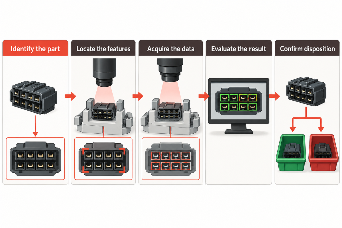
An automated inspection station presents a connector consistently, collects the required data, assesses those data against a product recipe and sends a result to line control. Its inspection process includes a response to an abnormal situation: rejection, containment or review. Automated optical inspection, or AOI, provides the visual judgment within that process. Manual inspection can also support a defined review.
How does connector inspection automation work?
This station identifies the product and confirms its orientation. It captures images and/or measurements and compares them with defined acceptance criteria. It also ensures the results are associated with the physical parts. Line control can then release, reject or hold the part and provide the reason for its disposition.
- Identify the part — select the correct drawing revision and inspection recipe.
- Locate the features — stabilize the connector and establish the required references.
- Acquire the data — trigger lighting, cameras and other instruments at the appropriate point.
- Evaluate the result — apply dimensional limits or validated classification rules.
- Confirm disposition — verify the intended output and retain the result with its part identity.
In a published G2 Technologies connector inspection application, verification and orientation precede board-side scanning. Optical measurement and electrical testing can occupy different stations. This illustrates why process automation needs more than image processing.
Match the defect to the inspection method
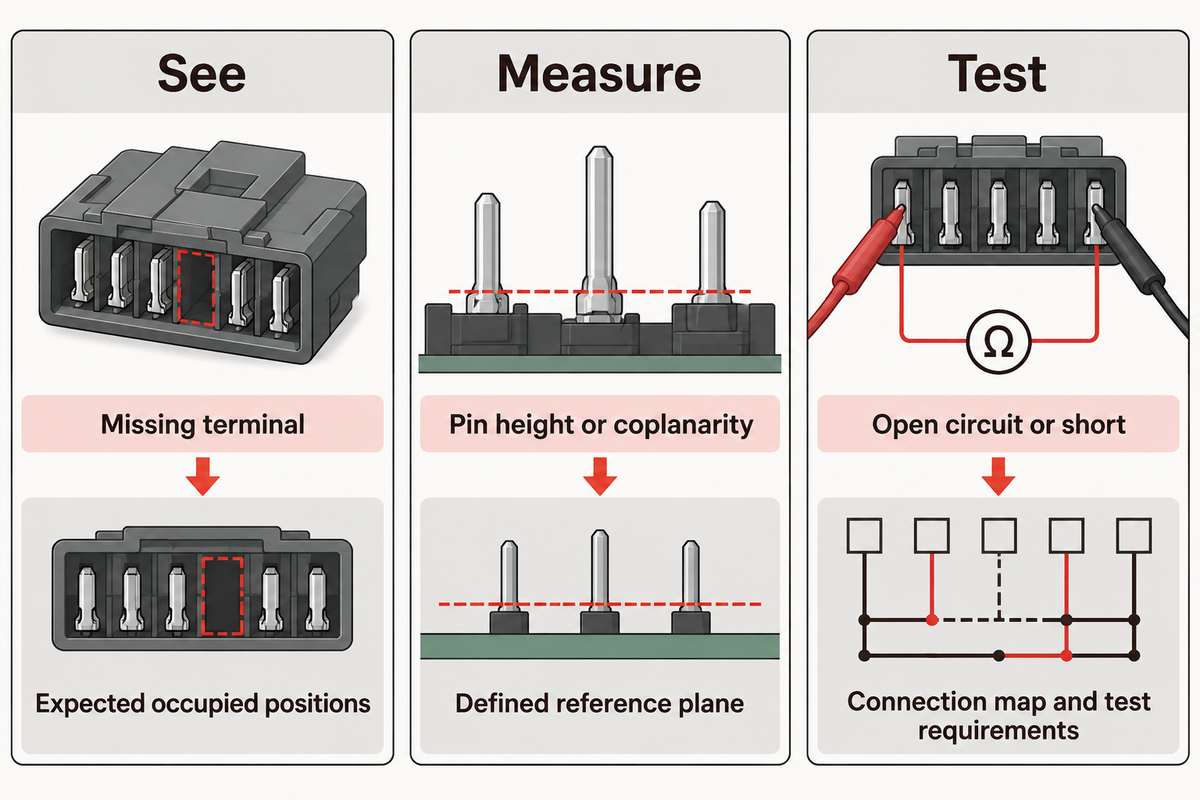
Associate the appropriate acceptance method with each property: images show presence and surface appearance, quantitative measurements reveal geometric position, and tests evaluate electrical function. Start with the defect definition and drawing reference, then determine if the required feature is accessible.
The See-Measure-Test Decision Tree below provides a practical means to implement the choice. “See” means classify surface appearance, “measure” means quantify geometry against a reference, and “test” means apply a functional or mechanical method. Connector quality can benefit from all of them. Different connector contact types allow for different observations.
| Condition to evaluate | Starting method | Required reference | What needs another check |
|---|---|---|---|
| Missing terminal | See: presence inspection | Expected occupied positions | Electrical connection quality |
| Wrong orientation | See: orientation recognition | Product key or asymmetric feature | Hidden contact condition |
| Bent pin or position error in the image plane | Measure: calibrated 2D view | Drawing datum and scale | Out-of-plane displacement |
| Pin height or coplanarity | Measure: calibrated side view or suitable 3D arrangement | Defined reference plane | Occluded surfaces |
| Housing crack or dent | See: appearance inspection | Agreed defect examples and limits | Concealed damage |
| Wrong marking | See: OCR or code reading | Expected text and recipe | Product performance |
| Open circuit or short | Test: electrical circuit test | Connection map and test requirements | Mechanical retention |
| Excess contact resistance | Test: resistance measurement | Specified method and limit | Surface geometry |
| Insufficient contact retention | Test: applicable mechanical method | Product-specific force and procedure | Electrical performance |
| Fiber end-face contamination | See: fiber inspection microscope | Applicable fiber acceptance criteria | Attenuation and return loss |
Measure terminal seating against the specified datum, and keep pin inspection for missing terminals, as a different check. A connector can have all terminals present and some of those terminals can be seated too high. A presence classifier can accept the connector even when a terminal is seated too high. Prior to adding height inspection, determine if the housing or mounting feature defines the datum. Movement of the entire connector can otherwise look like pin misalignment. With separate presence and height checks, make sure a passed presence check can’t override a failed height check.
Choose between 2D vision and 3D measurement
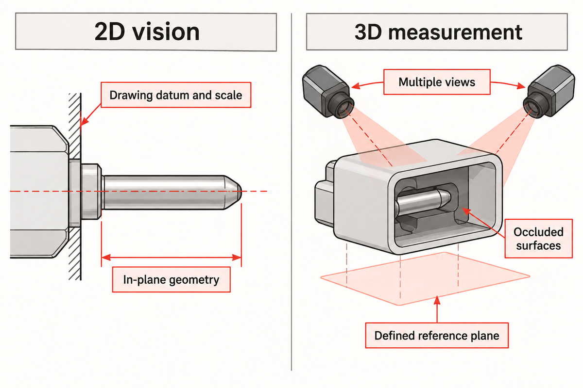
Opt for 2D vision when the info is visible in a stable image plane. A calibrated 2D side view can measure pin height when the pin tips and datum are visible in the measurement plane. Use 3D measurement when the required geometry is beyond that plane. A complex sensor can earn its place when measuring a property that a simpler view can’t resolve.
2D vision
- Supports presence, orientation and visible surface checks.
- Measures in-plane geometry with suitable calibration and presentation.
- Needs control of perspective, focus and contrast.
- Does not directly provide every height coordinate.
3D measurement
- Supports height, coplanarity and spatial position checks.
- Measures geometry relative to an established reference.
- Needs adequate access, signal quality and calibration.
- Can require multiple views where the housing creates shadows.
The G2 case used connector clips to create a reference plane and posts to locate contacts. Its mating side inspection combined scans in opposite directions. Craig Borsack, president of G2 Technologies, elaborated on the optical problem.
“Two scans are required due to shadowing effects created by the connector shell as the part is scanned from one side.”
Craig Borsack, G2 Technologies, Vision Systems Design
In the case of a shrouded design, draw the viewing direction beside the feature to inspect. An optical 3D sensor doesn’t see through walls or contacts that block its view. The practical choices include other views, different fixtures, or a different measurement method. This access question is especially relevant to blind-mating connector assembly.
Align the measurement coordinate system with the drawing reference. Extra data points don’t correct a misplaced datum: the calculation must describe the same geometry that the drawing specifies.
Build a stable image before adding AI
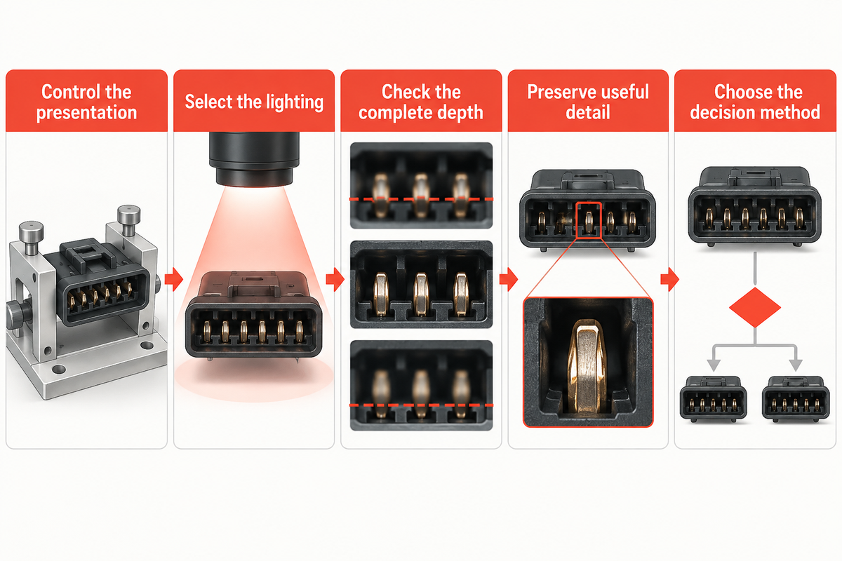
Stable imaging starts with repeatable part placement, even lighting, correct focus, and sufficient detail at the defect. Rule-based algorithms work well to check explicit features like presence and position. Deep learning models can help classify variable appearances, as long as the training examples differentiate acceptable variation from real defects. AI vision still relies on stable image quality.
- Control the presentation: locate the part without hiding the feature or introducing deformation.
- Select the lighting: test how bright surfaces, recesses and edges respond to the illumination angle.
- Check the complete depth: make sure the relevant pin regions remain resolvable.
- Preserve useful detail: assess the final processed image, including resizing and compression.
- Choose the decision method: use explicit measurements for dimensions and validated appearance models for visual classification.
Evident’s connector microscopy application illustrates the difficulty of focusing a pin’s root and tip together. This optical problem can be addressed by focus stacking, but the time required for acquisition and processing belongs in the inspection cycle. Likewise, the 2026 YOLO-HCS study resized images from 1536 × 1028 to 1280 × 1280 during training. Evaluate whether preprocessing preserves the small defect you need to detect. A high-resolution acquisition is helpful only if the relevant detail survives the processing.
Compare controlled images from both production lots, including known defects, before altering the decision threshold. In the case where a new lot of plating causes a brighter reflection on acceptable terminals, and a model trained on a different finish rejects those terminals, correct any unstable lighting first. If the change in appearance of the terminals is within acceptable limits of the product, add examples to development data and repeat the independent test. Keep the previous recipe available for comparison. Make sure to retain the same sensitivity to the original defect when changing the recipe to adjust for reflection.
For robotic loading, verify the handoff into the inspection fixture. Robotic arms can present a part consistently only when the gripping and locating arrangement supports the inspection requirement. Keep background clutter out of the viewing area and test the permitted presentation variation.
Keep optical inspection and electrical testing separate
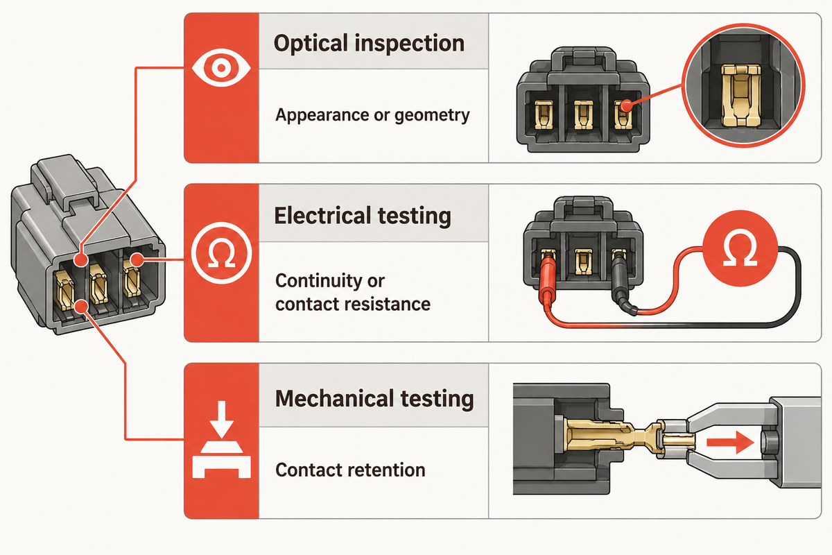
Optical inspection assesses appearance or geometry. Electrical connector inspection often combines that evidence with functional measurements. Electrical testing assesses other properties like continuity or contact resistance. Mechanical testing assesses other properties, like contact retention. Define each required property separately, even when several instruments share the same automated fixture and part identifier.
The BSI catalogue for the IEC 60512 series lists visual examination and dimensional examination as distinct test subjects. Choose the applicable specification and test method before setting the pass/fail limits. An image of a completed crimp does not replace the electrical or mechanical check associated with a connector crimping process.
Engineering note: define the measured quantity
For pin position, state the drawing datum, measurement direction, dimensional tolerance and acceptance rule together. Claims of high precision need a defined measured quantity and evidence of measurement performance. A camera resolution value isn’t a dimensional tolerance. Where measurement uncertainty matters near a limit, document how it affects acceptance rather than treating every displayed decimal as exact.
Fiber optic connector inspection requires its own scope. IEC 61300-3-35:2022 concerns debris, scratches and defects on fiber interfaces. It states that visual inspection supplements attenuation, return-loss and end-face parameter measurements. A ceramic ferrule and optical fiber therefore need different inspection criteria from electrical connector pins. For an automated fiber assembly route, see the guide to fiber-optic connector assembly.
Validate false rejects and missed defects
Validate with independently classified good parts and defective parts, and report results separately. A false reject is a good part that the system rejects. A missed defect is a defective part that the system accepts. Their rates address different questions. How often does unnecessary review occur? What’s the rate of defects that have escaped detection?
Have a qualified inspector determine the reference classifications and resolve disputed labels. Freeze the recipe prior to the final test. Keep physical parts used to test the recipe separate from the parts used to train or tune the model; repeated images of one connector are not independent production examples. NIST’s AI evaluation program uses blind data and a secluded environment to reduce contamination of training and test data sets. Follow this practice when handling connector samples.
| Test condition | What to include | Record separately |
|---|---|---|
| Known good production parts | Normal permitted appearance variation | False rejects / known good parts |
| Known defective parts | Each required defect class | Misses / defective parts in that class |
| Near-limit dimensions | Reference-measured parts around the boundary | Decision and reference measurement |
| Repeated presentation | Unload and reload the same part | Measurement spread and label changes |
| Different production lots | Accepted finish and molding variation | Results by lot |
| Different shifts or days | Representative operating conditions | Drift and between-run changes |
| Recipe changeover | Product variants and deliberate mismatch | Selection and identity errors |
| Missing acquisition | No image or incomplete measurement | Hold/reject response |
| Reject-path challenge | Known failed parts through routing | Confirmed destination |
| Restart and recovery | Interrupted cycles and queued parts | Identity and disposition after recovery |
NIST’s measurement guidance isolates short-term repeatability from day-to-day and run-to-run variability. Measurement systems will display short-term repeatability with stable repeated readings during setup. For longer-term variability, compare readings across production shifts. Distinguish random variations within a run from consistent shifts between runs. For dimensional decisions, refer to ISO/IEC Guide 98-4 to understand how measurement uncertainty and acceptance limits impact the risk of accepting nonconforming items or rejecting conforming items. The acceptance limits can be established to balance those risks.
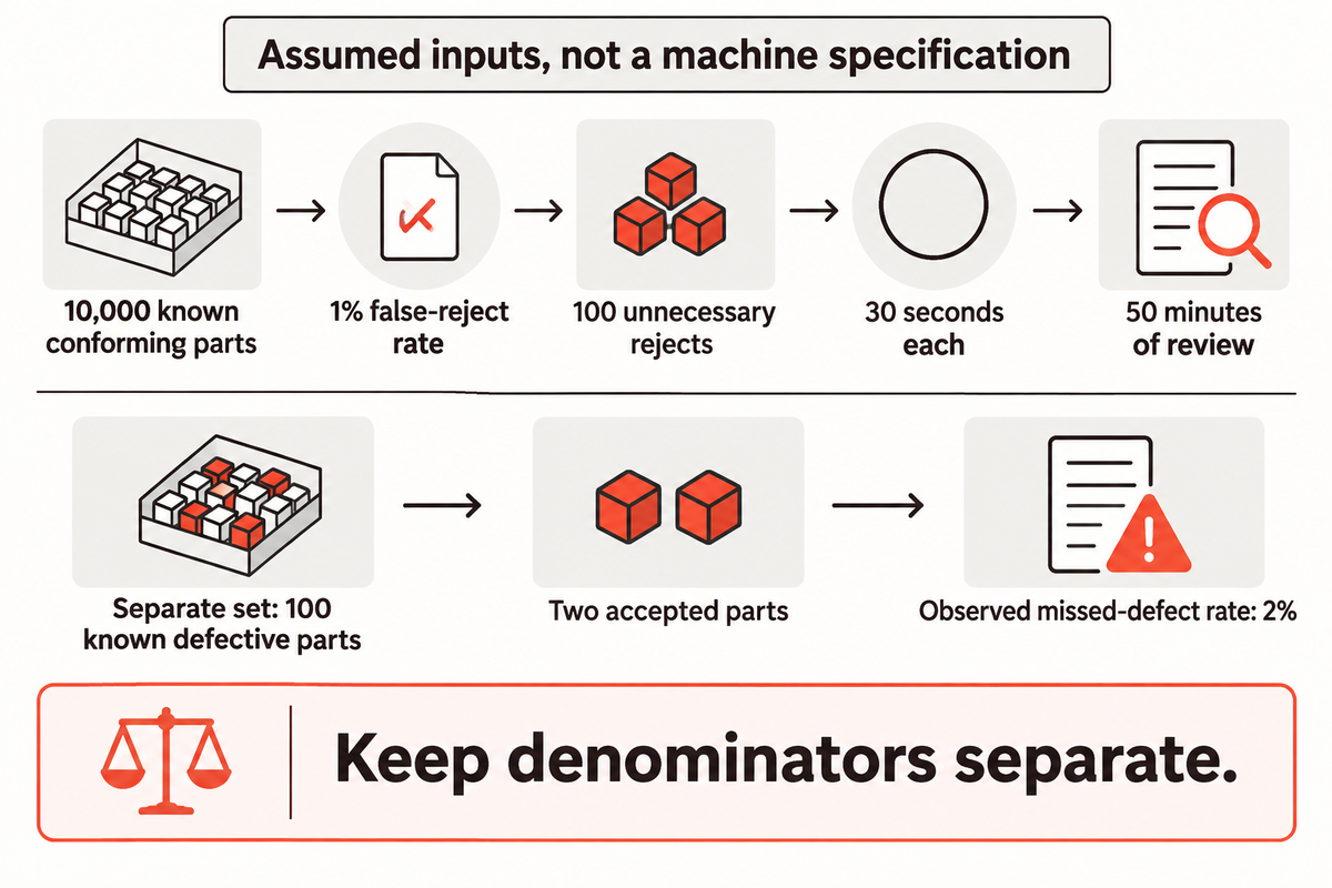
Worked example, assumed inputs, not a machine specification: inspect 10,000 known conforming parts with a 1% false-reject rate. That creates 100 unnecessary rejects. At 30 seconds of rechecking each, the review workload is 50 minutes. In a separate challenge set of 100 known defective parts, two accepted parts produce an observed missed-defect rate of 2%. Denominators of samples must be kept separate.
Report sample counts, observed rates and associated confidence bounds for a finite set of samples along with defect mix and operating conditions. NIST’s binomial guidance explains why a normal approximation may be unsuitable when samples or failure counts are small. With zero observed misses, one can’t be certain of the production’s performance.
Connect inspection results to line control
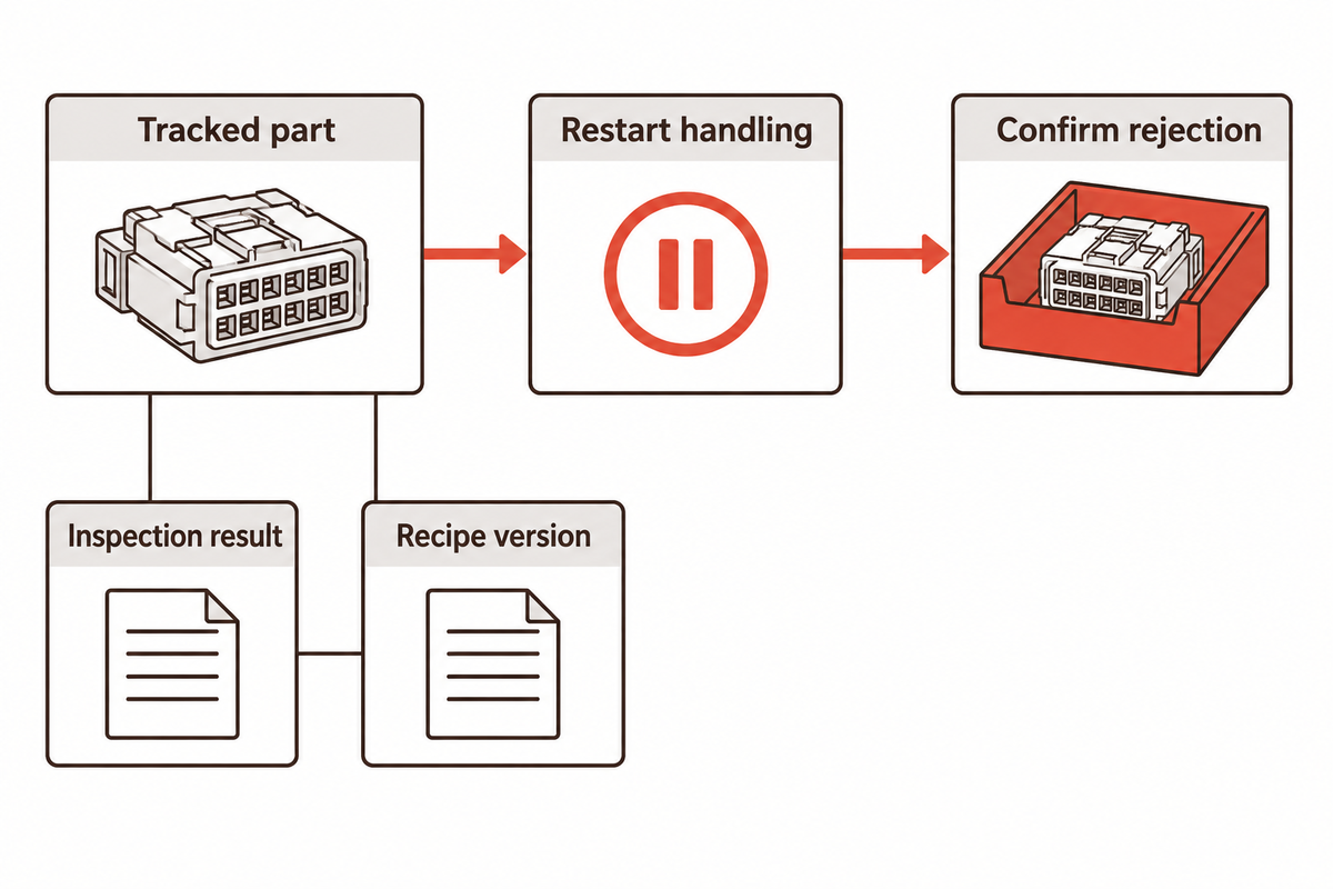
Line integration needs to preserve the result of inspection with the corresponding physical connector until the final destination is confirmed. Define the actions to be taken if an image is missing, if a result is received later than expected, if identification fails, or if the reject container isn’t available. Treat these conditions as operating conditions in a control plan.
- Associate each result with a tracked part or controlled fixture position.
- Exchange trigger, busy, complete and result signals with defined timing.
- Confirm rejection instead of relying only on the eject command.
- Retain recipe version, measurements and useful failure images with the identifier.
- Specify restart handling for parts still between inspection and discharge.
For example, inspection after a pin insertion machine finds a missing contact, and a conveyor stop happens before the part gets to the reject point. If restart logic advances the result queue incorrectly, the next good connector can be rejected, while the defective one can continue. In end-to-end acceptance testing, simulate that interruption. Also confirm the failed part’s destination and neighboring parts. This test checks the connection between inspection and part handling; checking stored images alone would miss the routing error.
Human operators need clear instructions for held parts and damaged connectors. Define who may release a reviewed part, who authorizes rework and how the subsequent inspection is recorded. Human inspectors should see the relevant image and failure reason, rather than only an unexplained red indicator.
Define the project scope before comparing costs
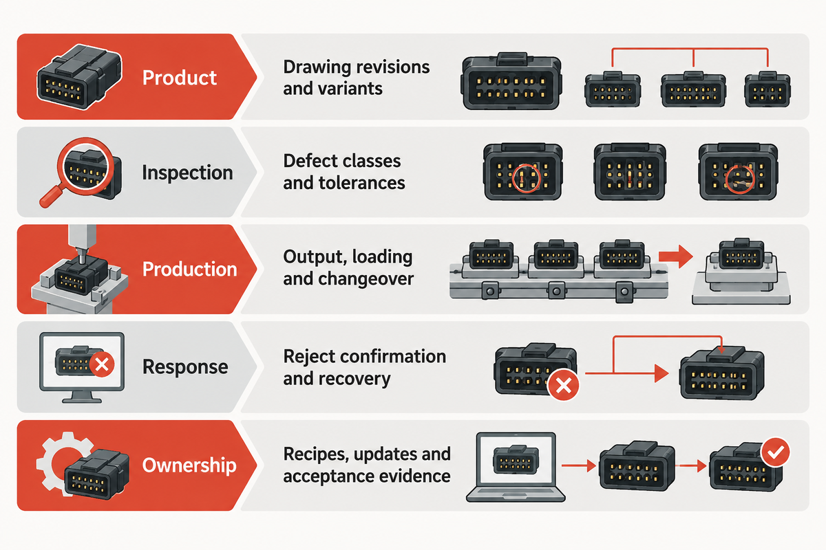
Compare the costs of different proposals for the same inspection scope, product mix, handling duty, and acceptance tests. The cost includes fixtures, lighting, instruments, software, controls, changeover, and support. Review labor also matters: a station that detects defects but produces a large false-reject queue can shift work downstream instead of removing it.
VDI/VDE/VDMA 2632 Part 2:2024-11 explains requirements and system specifications of machine vision. Its focus is on identifying, communicating and adapting to influencing factors in the early stages of a project with the project partner. A specification should be developed jointly by a buyer and seller to enable comparison of quotes.
- Product: drawing revisions, variants, contact geometry and acceptable cosmetic variation.
- Inspection: defect classes, measured quantities, tolerances and reference labeling methods.
- Production: required output, loading method, changeover frequency and available space.
- Response: reject confirmation, review workflow, traceability and recovery behavior.
- Ownership: responsibility for recipes, model updates, fixtures, spare parts and acceptance evidence.
Inquire if suppliers can break down the complete cycle, including loading, settling, acquisition, processing, transfer and disposition. Some actions overlap, while others consume the same station time. Review queues can become a separate constraint in high-volume production. A sensor’s profile rate is not the rate at which complete connectors are inspected. Evaluate speed and efficiency over a representative batch and include interruptions and recovery. Use the methodology to explain downtime and throughput.
For finance, convert the documented false-reject workload into operational costs, using your own labor rate. Include review labor when estimating cost savings from automation. For quality, retain defect-class results. For procurement, compare the same scope and support. Engineering management can then assign responsibility for changes that affect the inspection of connectors. After those inputs are defined, consider ZEUEE’s connector inspection automation solutions for equipment.
Understand what is changing in connector inspection
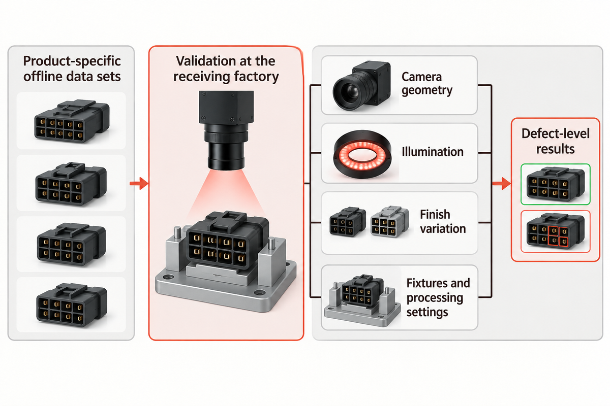
Recent connector inspection work has focused on small defects, dense pin layouts and reuse of prior work. High-performance computing and data center hardware are some applications behind this work. Evaluate these through defect class outcomes, image conditions and transfer testing.
Instrumental’s March 2026 announcement describes pooling data from pin locations into a shared model for high-density connectors. This can help teams gain control of repeated features through learning from other locations. It also makes recipe version control more important when teams deploy models across production sites.
The 2026 YOLO-HCS connector-terminal study considers small-defect detection using data sets comprising 177 and 633 original images. The study recognizes the difference between counts and annotated defect instances and addresses class imbalance. The study evaluates small-defect detection on product-specific offline data sets. Use its treatment of counts and instances of defect and class imbalance to plan tests and evaluate factory yield under production conditions.
Can the same model be used across different factories?
A model can be transferred, but it needs validation at the receiving factory against that factory’s acceptable parts and defect samples. Compare camera geometry, illumination, finish variation, fixtures and processing settings. Freeze a version for acceptance testing, record differences from the development site and retain a controlled route for later updates.
Compare AI-driven inspection solutions using results for the defects most relevant to the product, as a model can outperform another on aggregate while detecting a rare defect less reliably. Assess performance and reliability by comparing defect-level results for the relevant operating conditions. Anomaly detection and segmentation also need acceptance definitions; highlighting an odd region is useful only if the production personnel understand how that region should affect disposition.
Frequently asked questions
What are vision inspection systems?
Vision inspection systems use cameras, lighting and software to evaluate visible product features. For connectors, they can check terminal presence, alignment, surface condition and markings. A complete installation also needs controlled presentation and a response to the result, such as rejection or review. Height measurements require an appropriate measurement arrangement rather than an ordinary top image.
What is an in-line inspection?
An in-line inspection checks a part within its production flow, rather than sending it to a separate inspection room. For connectors, the station may inspect immediately after terminal insertion or before packing. Its result must remain associated with the correct part, and the line must confirm that rejected pieces reach the intended destination.
Is connector inspection automation required?
Not necessarily: automation is a process choice driven by the product drawing, customer requirements, defect risks and production needs. A requirement to inspect a feature doesn’t automatically prescribe a camera or an automated station. Choose automation when the required checks can be demonstrated reliably at the intended rate, with documented handling of failures and uncertain results.
Where does connector inspection automation work?
It’s used in connector and electronics production where parts can be presented consistently and acceptance features can be observed or measured. Applications include terminal presence, alignment, housing condition and markings. Hidden features need another view or a different test method.
How often should an inspection system be checked?
Check after changes to fixtures, lighting, software or product recipes and after maintenance; set routine checking intervals using process risk, equipment stability and the control plan, and revise them against actual drift and failures. Keep known reference parts or another verification method under control. A scheduled check should confirm both the measurement or classification decision and the physical reject response; a camera that identifies a bad part correctly can still feed it forward if routing fails.
Can a camera inspect pins hidden inside a connector?
Yes, if a usable optical path reaches the pin being evaluated. Connector walls and neighboring pins can obscure that path. Additional views, mirrors or another sensing method may help, but a three-dimensional sensor doesn’t automatically reveal every concealed surface or contact.
What samples should a supplier receive before quoting?
Provide representative production parts, the current drawing, the required inspections, and known defects with agreed classifications. Include acceptable variation such as plating appearance, molding marks and different connector versions. Add the intended production rate, handling constraints and required reject response. Near-limit samples are useful because a missing pin may be easy to identify while a small positional error is harder. Agree how sample labels are established before evaluating a proposed system.
Prepare your connector inspection brief
Bring your connector drawings, product variants, defect examples and required production rate to the equipment discussion. These inputs help define the inspection scope and acceptance trial. Learn about ZEUEE, or send the project details to discuss a suitable next step.
References & Sources
- Vision Systems Design: G2 connector pin-height inspection application.
- BSI: IEC 60512 tests and measurements catalogue.
- IEC: 61300-3-35:2022 fiber end-face inspection.
- NIST: AI Technology Evaluation; measurement variability; exact binomial confidence limits.
- ISO: Guide 98-4, measurement uncertainty in conformity assessment.
- VDI/VDE/VDMA: 2632 Part 2:2024-11, machine-vision specifications.
- Lin et al.: YOLO-HCS connector-terminal defect detection, 2026.
Assumed examples are explanatory scenarios, not ZEUEE production measurements. Third-party systems and research remain attributed to their respective organizations.
WHY WE WRITE THIS
About ZEUEE Engineering Insights
ZEUEE shares technical guides based on real automation project experience. Since 2005, we have designed and manufactured non-standard automation equipment for connector assembly, wire harness production, robotic lines, vision inspection, and smart factory upgrades.
Founded in 2005
20,000 m² production base
120+ specialists
150+ R&D patents
ISO9001:2015 certified