Get in touch with Zeyu lntelligent Industrial Company
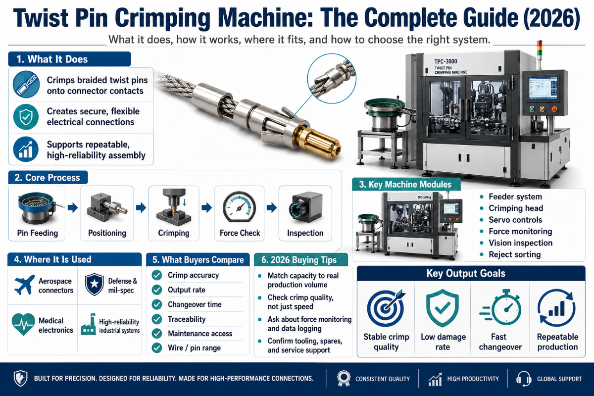
A twist pin crimping machine is the specialized equipment that strips, twists, and crimps the helically wound wires of a twist-pin (hyperboloid) contact onto a conductor. Unlike a hand crimper that closes a single stamped barrel, this machine forms a multi-wire spring contact and terminates it to a repeatable crimp height — the difference between a connection that survives 100,000 mating cycles and one that fails on the test bench. This guide explains how these machines work, the standards that judge their output, and how to choose one.
Quick Specs: Twist Pin Crimping Machines
| Contact type | Twist-pin / hyperboloid (multi-wire helical spring) |
| Conductor range | ~32–12 AWG, machine-dependent |
| Core machine jobs | Feed → strip → twist → crimp |
| Crimp standards | IPC/WHMA-A-620F (2025) · MIL-DTL-22520 / M39029 · NASA-STD-8739.4 |
| Crimp height tolerance | Typically ±0.02 mm of the terminal spec |
| Quality control | Crimp height, pull-force (≥90% wire UTS), crimp force monitoring |
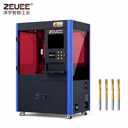
For the production-ready machine itself — models, contact compatibility, and throughput — see ZEUEE’s twist pin crimping machine page. This article is the background a buyer needs before that conversation.
What Is a Twist Pin Crimping Machine?
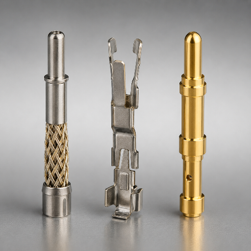
Start with the contact, because the contact is what makes the machine unusual. Conventional pins are stamped from flat metal and folded into a barrel. A twist pin is built differently. In the classic design described in US Patent US4358180A, a core of soft oxygen-free copper is surrounded by a cluster of beryllium-copper spring wires helically wound around the core; specific commercial designs vary. Those outer wires bulge outward and, when inserted into a matching socket, press against the mating pin at multiple points around its circumference.
This is the hyperboloid contact family that underlies modern hyperboloid connectors. Spring wires form a basket that is twisted at each end, so the mid-section narrows into a resilient cage. That geometry produces line contact at many points 360° around the pin instead of the two or three rubbing points of a stamped socket. Because the wires are light and low in mass, they follow the abrupt motion of a vibrating pin without losing contact — which is why hyperboloid contacts have a 50-year track record in military and aerospace connectors and tolerate up to 100,000 insertion/extraction cycles with little degradation.
A twist pin crimping machine exists because you cannot make that contact with a simple press. This machine does four jobs in sequence: it feeds the wire and contact, strips the insulation to a controlled length, twists the spring-wire cluster into its hyperboloid geometry, and crimps (or swages) the barrel to capture the wires and terminate the conductor. Patent US7775841B2 describes exactly this finish step — a tubular body “deformed by rolling, crimping or swaging to permanently capture” the angled wires. Twisting and crimping are not two separate machines; on a purpose-built cell they are one coordinated motion.
📐 Buyer reality
For an industrial buyer in EU or US aerospace and medical programs, the structural reason to accept the twist-pin’s higher cost is risk: a stamped contact that fails after 5 years of vibration is more expensive than the one that prevents it. ZEUEE engineers the twist-and-crimp motion into one machine, and the factory will provide a sample crimp report on request so you can verify the geometry before you commit. (twist-pin construction: US Patent US4358180A)
Twist-Pin vs Stamped vs Machined Contacts
Buyers often ask which contact construction is “best.” The honest version is that it depends on what you are protecting against — vibration, cost, or current. Here is the trade-off laid out across the three constructions you will actually compare. We will not claim a twist-pin always wins; for a low-cost, low-vibration board connector, a stamped contact is the right call.
Twist-Pin vs Stamped vs Machined Contact Crosswalk
| Property / Contact type | Twist-Pin (Hyperboloid) | Stamped & Formed | Machined (Turned) |
|---|---|---|---|
| Construction | Helically wound spring wires on a core | Folded from flat sheet | Turned from bar stock |
| Contact points | Many, 360° line contact | 2–3 wiping points | 1 continuous band |
| Contact resistance | ~3 mΩ (Cinch twist-pin) | ~8 mΩ (typical M83513) | Low, design-dependent |
| Shock / vibration | Excellent — wires track the pin | Moderate | Good |
| Mating cycles | Up to 100,000 | ~500–5,000 | ~5,000–10,000 |
| Mating force | Low per contact | Moderate | Higher |
| Relative cost | Highest | Lowest | Mid-to-high |
| Termination method | Twist + crimp / swage | Crimp | Crimp or solder |
| Typical conductor | ~32–20 AWG signal | ~28–10 AWG | ~24–12 AWG |
| Typical industry | Aerospace, defense, medical, test | Automotive, consumer | Industrial, mil circular |
| Governing spec | MIL-DTL-83513, IPC-620 | IPC-620, USCAR-21 | MIL-DTL-38999, IPC-620 |
Resistance figures: Cinch twist-pin contacts (~3 mΩ) vs standard M83513 (~8 mΩ); mating-cycle and cost bands are typical ranges, not absolute limits.
Read the table as a decision, not a scoreboard. If your product sees salt-fog, thermal cycling, and 15 years of vibration, the twist-pin’s redundancy earns its cost. If it sees a benign cabinet and a price target, a stamped contact terminated on an ordinary crimper is the engineering-correct answer.
📐 Buyer reality
For an industrial buyer comparing on price, the hidden problem is field risk: a stamped contact costs less, but a 1% failure rate over 100,000 cycles is the structural reason aerospace specifies the twist-pin. ZEUEE engineers the geometry to a repeatable spec rather than leaving it to a hand tool; request a sample cross-section to see the difference. (hyperboloid torsion assembly: US5326289A)
How Twist-Pin Crimping Actually Works
A crimp is a gas-tight cold weld. During each cycle the press compresses the barrel metal around the conductor strands until they deform into one solid mass with no air gaps — no heat, no solder, no flux. Get the compression right and the joint outlasts the wire. Get it wrong and the connection looks fine but fails a pull test. Repeating that compression to a controlled crimp height is the whole job of a twist pin crimping machine, measured from the top of the formed crimp to its lowest radial surface.
5-Zone Crimp Anatomy
Every acceptable crimp shows five zones. Inspectors read them left to right:
- 1.Conductor brush — a short length of bare strands visible past the conductor barrel, proving the wire reached the back of the crimp.
- 2.Conductor barrel — the load-bearing crimp, compressed to the terminal’s crimp-height spec.
- 3.Transition — the gap between conductor and insulation crimps.
- 4.Insulation barrel — grips the insulation for strain relief without piercing it.
- 5.Bell-mouth — a slight outward flare at the barrel ends.
⚠️ Important
Many people reject the bell-mouth flare, assuming it is a defect. It is not. Under all three IPC classes the bell-mouth is a preferred condition: it funnels the strands into the barrel and keeps the sharp barrel edge from nicking the wire. The defect is the absence of a bell-mouth, not its presence.
Crimp height is the master variable because it sets compression for the whole range of wire stranding, plating, and terminal material. Field data shows how sensitive it is. In one documented production case, a crimp-height drift of just 0.08 mm after an applicator ram was cleaned and reset caused 11 of 60 samples to fall below the minimum pull-force spec; the same source reports that pushing crimp height beyond ±0.02 mm let air pockets form inside the joint and raised contact resistance by as much as 15%. Treat these as indicative field figures, not universal constants.
Why use 1.6 mm for the conductor crimp and 1.9 mm for the insulation crimp?
Because the two zones do different jobs. Conductor crimps (smaller, e.g. 1.6 mm) must compress copper strands into a gas-tight mass — too loose and resistance climbs, too tight and you cut strands. Insulation crimps (larger, e.g. 1.9 mm) only grip the insulation for strain relief; crushing it to the conductor dimension would pierce the jacket. Purpose-built tooling sets both heights independently, which is exactly why a single hand tool struggles to match a purpose-built crimping machine.
📐 Engineering Note
Target the terminal maker’s crimp-height value, hold ±0.02 mm, and validate with a pull test (IPC/WHMA-A-620 uses a 25 mm/min pull rate). Pull-force minimums are specified per wire size in the terminal datasheet and in standards tables — UL 486A-B, MIL-T-7928, and IPC/WHMA-A-620 each publish their own values, and they differ. Do not assume one number; read the minimum for your exact wire size and terminal from the table that governs your product, then test to it. Log crimp height and pull force together; a passing pull force with a drifting crimp height is an early warning, not an all-clear.
📐 Buyer reality
The expensive problem for a US or EU industrial buyer is a crimp that looks fine and fails a pull test weeks later. The structural reason ZEUEE engineers crimp-height control to ±0.02 mm is that a 15% resistance rise from a hidden air gap is invisible until the field returns it. Request a detailed crimp cross-section report against IPC/WHMA-A-620F before committing. (crimp/swage capture method: US7775841B2)
Crimp Quality Standards: IPC/WHMA-A-620 and M39029
Two document families decide whether your crimp is acceptable. IPC/WHMA-A-620 is the visual and mechanical acceptance standard for cable and wire assemblies; its current edition, Revision F, was released in 2025 and replaces Revision E from 2022. For a military removable crimp contact, MIL-DTL-22520 governs the crimp tools and MIL-DTL-39029 (the M39029 series) governs the contacts. For spaceflight, NASA-STD-8739.4 layers on certified-operator and tool-control requirements.
IPC-620 sorts work into three classes. Class 1 is general electronics, Class 2 is dedicated-service products, and Class 3 is high-reliability hardware — aerospace, medical, and military. For crimping, the practical difference lives in pull-force test frequency, cross-section requirements, and how much marginal condition is tolerated. Several conditions that pass “with caution” under Class 2 are outright rejects under Class 3.
IPC-620 Class 1/2/3 Crimp Acceptance Scorecard
| Acceptance criterion | Class 1 | Class 2 | Class 3 |
|---|---|---|---|
| Conductor brush visible | Preferred | Required | Required |
| Bell-mouth present | Preferred | Preferred | Required |
| Insulation support | Recommended | Required | Required |
| Pierced insulation | Reject | Reject | Reject |
| Crimp height in spec | Required | Required | Required |
| Pull-force test | Sample | Periodic | Frequent + logged |
| Cross-section analysis | Optional | As needed | May be required |
| Cut strands allowed | A few | Limited | Very limited |
| Cut-off tab length | Relaxed | Controlled | Controlled |
| Marginal-condition tolerance | Higher | Moderate | Lowest |
Summarized from IPC/WHMA-A-620 acceptance principles; consult the current Revision F for exact dimensional limits and photographic criteria.
📐 Buyer reality
For a Class 3 industrial buyer, the risk of a marginal crimp is a 1,000-unit latent-failure problem at 100,000 contacts. The structural reason ZEUEE engineers traceable, certified output to IPC/WHMA-A-620F is that an aerospace or medical audit rejects undocumented acceptance. Request an engineering estimate for the tier your volume needs. (workmanship requirements: NASA-STD-8739.4)
Climbing the Crimp Automation Ladder: Hand Tool to Fully Automatic
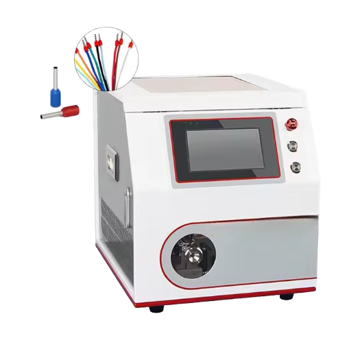
“Twist pin crimping machine” spans equipment from a hand tool you squeeze to a benchtop crimping machine and on to an inline cell that cuts, strips, twists, crimps, and tests without an operator touching the wire. Climbing the ladder buys repeatability and traceability; it costs capital and setup time. Which rung is right depends on volume and reliability class, not on prestige.
4-Tier Crimp Automation Ladder
| No. | Machine tier / type | Repeatability | Crimp force monitor | Best volume |
|---|---|---|---|---|
| 1 | Tier 1 — Manual hand crimper | Operator-dependent | None | Repair, prototype |
| 2 | Tier 1 — Ratchet tool with positioner | Good (full-cycle ratchet) | None | Low volume, mil-spec field |
| 3 | Tier 2 — Benchtop terminator | High (fixed tooling) | Optional | Low-to-medium series |
| 4 | Tier 2 — Pneumatic bench press | High | Optional | Medium series |
| 5 | Tier 3 — Semi-auto strip + crimp | Very high | Common | Medium production |
| 6 | Tier 3 — Semi-auto strip + twist + crimp | Very high | Common | Twist-pin medium runs |
| 7 | Tier 4 — Fully automatic lead maker | Highest | Standard | High volume |
| 8 | Tier 4 — Automatic twist-pin cell | Highest | Standard | High-volume twist-pin |
| 9 | Tier 4 — Inline cell with 100% CFM | Highest + traceable | 100% inline | Regulated high volume |
Do you really need to crimp wires by hand?
In aerospace it is a screening question — a senior technician will ask a junior “do you know how to crimp wires?” precisely because hand crimping exposes whether someone understands crimp height and pull force. But “can do it by hand” and “should do it by hand at volume” are different. A certified ratchet tool produces a sound mil-spec crimp one at a time; once you need hundreds of repeatable, logged terminations a day, the bench and semi-auto tiers remove the operator variable that hand crimping cannot.
📐 Buyer reality
The hidden cost on the wrong rung is rework: an industrial buyer who picks a hand tool for a 10,000-unit-per-day line trades a 30% slower process for an operator-variable failure rate. The structural reason ZEUEE engineers each tier with crimp force monitoring is traceability, not prestige. Request a detailed engineering estimate for your daily volume. (hyperboloid contact assembly: US6464546)
How to Inspect a Crimp: Pull Test, CFM, and Cross-Section
Three checks separate a verified crimp from a hopeful one, and a good twist pin crimping machine supports all three.
How do you know the crimp is good?
You measure it three ways and agree the results:
The crimp verification routine
- Crimp height — measure with a micrometer to the top-of-crimp datum; compare to the terminal spec within ±0.02 mm. Fast, non-destructive, done first.
- Pull-force (tensile) test — clamp the terminal, grip the wire, pull at 25 mm/min until separation. Target the minimum published for your wire size in the terminal datasheet or the governing standard’s table (UL 486A-B, MIL-T-7928, or IPC/WHMA-A-620) — the figures differ by standard, so use the one your product is built to.
- Cross-section analysis — cut, polish, and inspect the barrel for compression and voids; this reveals over- or under-crimping that a pull test alone can hide.
On automated equipment, crimp force monitoring (CFM) turns sampling into 100% inspection. It records the force-versus-displacement curve of every crimp and flags any cycle that drifts from the learned signature — a missing strand, a stripped-too-short wire, a worn die. Mature lines target a process capability of Cpk ≥ 1.67, the threshold that keeps defects below a few parts per million. That is the practical reason automation wins at volume: it does not just crimp faster, it proves every crimp.
“A passing pull force with a drifting crimp height is an early warning, not an all-clear. The crimp-height data tells you the process is moving before the pull test starts failing parts.”
— Practitioner guidance commonly reported in crimp-process QC, summarizing IPC-620 crimp validation
📐 Buyer reality
The gap most US and EU buyers miss is that a passing pull test can still hide a drifting process — the structural reason ZEUEE engineers 100% crimp-force logging rather than sampling. A small crimp-height drift that quietly pushes parts below the pull-force minimum is the problem you want caught inline. Download the crimp-validation guide preview before your first-article inspection. (crimp workmanship acceptance: NASA-STD-8739.4)
How to Choose a Twist-Pin Crimping Machine
Most selection mistakes are not about the headline machine; they are about the tooling and the contacts it has to handle. Wrong-die errors alone are costly: using a 10–12 AWG die on a 16 AWG terminal yields roughly 30% less pull strength. Work the checklist below before you compare brands.
- ✔1. Contact family. Twist-pin/hyperboloid, or also a Deutsch pin crimper, molex pin crimper, JST, or D-sub format? Confirm the machine’s applicators cover every contact you build.
- ✔2. AWG range. Match the conductor band (e.g. 32–20 AWG signal vs 16–12 AWG power). One machine rarely spans both well.
- ✔3. Twisting capability. Twist-pin contacts need controlled wire twisting before crimping — confirm it is integrated, not a manual pre-step.
- ✔4. Crimp force monitoring. For Class 3 work, inline CFM with data logging is non-negotiable.
- ✔5. Crimp-height repeatability. Ask for the documented tolerance; ±0.02 mm is the working target.
- ✔6. Changeover time. Mixed-product shops live or die on applicator swap speed.
- ✔7. Standards alignment. Confirm output is judged against IPC/WHMA-A-620F and, where relevant, M39029 / NASA-STD-8739.4.
Condition → tier recommendation
- Repair / certification / field mil-spec → Tier 1 certified ratchet tool with positioner.
- Low-to-medium series, mixed contacts → Tier 2 benchtop terminator.
- Medium twist-pin production, traceability needed → Tier 3 semi-auto strip-twist-crimp with CFM.
- High-volume, regulated (aerospace/EV/medical) → Tier 4 automatic cell with 100% CFM.
When you have matched a tier to your volume and class, compare specific machines on the twist pin crimping machine page, or browse the full connector assembly machines range.
📐 Buyer reality
For an industrial buyer matching contacts to a machine, the expensive mistake is a wrong-die error that cuts pull strength by 30%. The structural reason ZEUEE engineers integrated twisting is that a manual pre-twist step is where inconsistency enters. Hyperboloid assembly is documented in US5326289A. Send your contact part number for a specific compatibility estimate before you buy. (hyperboloid contact patent: US7775841B2)
Where Twist-Pin Crimping Fits in Cable Assembly
A twist pin crimping machine is one station in a longer line. In a typical high-reliability line the flow runs: cut → strip → twist → crimp → insert → continuity test. Your crimping machine owns the strip-twist-crimp middle; upstream a cutter measures and cuts conductors, and downstream an operator inserts the finished contacts into the connector housing and a tester verifies every circuit.
That placement matters for buying decisions. If you already run automated cut-and-strip, a semi-auto crimp cell drops in cleanly. If you are still cutting by hand, the crimp machine’s repeatability is undermined by inconsistent strip length upstream — which is itself a top crimp-failure cause.
Can you reuse a connector by extracting the pins?
Sometimes, with care. A connector pin extraction tool releases the contact’s locking lance so the terminated contact slides out of the housing for rework or re-pinning. Both the housing and a sound contact can be reused; a contact whose crimp you cut off cannot — once removed, re-terminating means a fresh contact and a fresh crimp. For twist-pin contacts especially, treat extraction as rework with full re-inspection, not a shortcut. Practitioners commonly report that reused contacts with marginal crimps are a recurring field-failure source.
📐 Buyer reality
The trade-off a US or EU industrial buyer faces in 2026 is buying for today’s volume versus tomorrow’s audit. With EV wiring automation growing 20.2% a year, the structural reason ZEUEE engineers 100% crimp force monitoring in now is that inline traceability is becoming the default audit expectation, not a premium. Request a detailed specification worksheet for your program. (cable assembly workmanship: NASA-STD-8739.4)
What’s Changing in High-Reliability Crimp Automation
Two forces are reshaping this equipment in 2025–2026: a standard update and a demand surge. On the standards side, IPC/WHMA-A-620F arrived in 2025, strengthening crimped-termination guidance and aligning with IPC J-STD-001 — buyers writing new purchase specs should reference Revision F, not the 2022 Revision E.
On the demand side, the wider cable-assembly market is forecast at roughly USD 95.9 billion in 2025 rising to about USD 100.47 billion in 2026 (~5.3% CAGR), while the EV wiring automation segment is projected to grow from USD 8.5 billion in 2025 toward USD 37.0 billion by 2033 at a 20.2% CAGR. High-voltage EV architectures, ADAS, and aerospace are pulling production toward servo-driven cells with 100% crimp force monitoring rather than sample pull tests.
💡 What to do about it
If you are specifying a machine this year, weight inline CFM and data logging heavily — they are becoming the default audit expectation in regulated cable-assembly work, not a premium option. And spec IPC/WHMA-A-620F explicitly so your acceptance criteria match the edition your auditor will use.
One honest caveat on the “crimp beats solder” narrative that drives twist-pin adoption: crimping is mandated for vibration and thermal cycling by SAE/USCAR-21, IEC 60352-2, and IPC/WHMA-A-620 for good reason — the gas-tight cold weld has no heat-affected zone to crack. But it is not an absolute. Hybrid crimp-and-solder joints still appear in some EV battery packs where a specific resistance or sealing target drives the choice. Match the termination to the documented requirement — that is the lesson, which is exactly what the standards force you to document.
📐 Buyer reality
The honest version for any industrial buyer: the right twist pin crimping machine is the one whose documented crimp-height repeatability and standards alignment match your reliability class. ZEUEE engineers across four tiers, so the structural reason to choose a rung is your volume and audit requirement, not the price tag. Crimp acceptance for high-reliability programs is governed by workmanship standards such as NASA-STD-8739.4. Request a tailored specification estimate to compare options.
Frequently Asked Questions
Q: What is a twist pin contact and why is it called a “twist pin”?
View Answer
A twist pin is a hyperboloid contact built from a soft copper core wrapped in beryllium-copper spring wires that are helically twisted around it. The “twist” describes how those outer wires are wound so they form a basket that grips a mating pin at many points around its circumference. That construction, captured in US Patent US4358180A, is what gives the contact its low resistance and high vibration tolerance.
Q: How is a twist-pin crimping machine different from a hand crimp tool?
View Answer
A hand pin crimping tool closes a single barrel and depends on the operator for crimp height. A twist-pin crimping machine integrates feeding, stripping, controlled wire twisting, and crimping into one repeatable cycle, and can hold crimp height to about ±0.02 mm across thousands of contacts. On automated tiers it also adds crimp force monitoring, so every contact is verified rather than sampled — the gap that matters at production volume.
Q: What standards govern twist-pin crimp quality?
View Answer
The core visual and mechanical acceptance standard is IPC/WHMA-A-620, currently Revision F (2025). Military removable contacts add MIL-DTL-22520 for crimp tooling and MIL-DTL-39029 (M39029) for the contacts themselves. Spaceflight hardware follows NASA-STD-8739.4. Together they define crimp height, pull-force minimums, and the Class 1/2/3 acceptance criteria your inspector will apply during a first-article inspection or quality audit.
Q: How much does an automatic pin crimping machine cost?
View Answer
It varies widely by tier, from a benchtop terminator to a fully automatic cell with inline monitoring. Because price depends on applicators, contact types, and throughput, request a quote against your specific contact and volume.
Q: Can one machine crimp Deutsch, Molex, and JST contacts?
View Answer
Often yes, through interchangeable applicators or die sets, but only within the machine’s force and AWG range. A bench terminator that accepts mini-applicators can run many brands; confirm each contact you build has a qualified applicator before assuming coverage, since mixing an out-of-range die is a common crimp-quality failure.
Q: What AWG range can twist-pin crimping machines handle?
View Answer
Most cover a band rather than the full spectrum — signal twist-pin work commonly sits around 32–20 AWG, while power-oriented tooling runs heavier. Mil-spec tool families like M22520 span 12–32 AWG across variants.
Q: Is crimping better than soldering for high-reliability connectors?
View Answer
For vibration and thermal cycling, crimping is generally preferred and is mandated by SAE/USCAR-21, IEC 60352-2, and IPC/WHMA-A-620 for automotive and aerospace service life. A proper crimp is a gas-tight cold weld with no heat-affected zone, whereas a solder joint can crack at the rigid-to-flexible transition under vibration. That said, it is not absolute — some applications, including certain EV battery packs, use hybrid crimp-and-solder joints to hit a specific resistance or sealing target. Match the termination to the documented requirement rather than to a rule of thumb.
References & Sources
- NASA-STD-8739.4 — Crimping, Interconnecting Cables, Harnesses, and Wiring — NASA
- IPC/WHMA-A-620F (2025) — Requirements and Acceptance for Cable and Wire Assemblies — IPC / ANSI
- US Patent US4358180A — Twist Pin — USPTO
- US Patent US7775841B2 — Hyperboloid Electrical Contact — USPTO
- US Patent US5326289A — Female Hyperboloid Electrical Connector — USPTO
- MIL-DTL-22520 — Crimping Tools, Terminal, Hand or Power Actuated — U.S. Department of Defense
- What Is Hyperboloid Contact Technology? — Connector Supplier
- Cable Assembly Market Analysis 2026–2030 — Technavio
Related
About This Guide
ZEUEE (Shenzhen Zeyu Intelligent Industrial Science Technology Co., Ltd) designs and builds connector assembly and twist-pin crimping equipment, holding 150+ patents and ISO 9001:2015 certification as a National High-Tech and Sp-Inn (SRDI) Enterprise. This guide reflects standards from IPC, the U.S. DoD, and NASA together with published crimp-quality field data; it is written to help engineers specify equipment, not to replace the acceptance standard your program requires.