Get in touch with Zeyu lntelligent Industrial Company
A twist pin stress relief machine is one of the most misunderstood stations in connector manufacturing, partly because the phrase collides with a completely different industry. Search the term and Google mostly returns vibratory stress relief equipment for welded steel. That gear has little to do with the precision contacts inside a circular or rectangular connector. This guide separates the two worlds, explains what stress relief really means for a twisted-wire contact, and gives you a framework to decide whether your build actually needs the step.
Quick Specs: Stress Relief for Twist-Pin Contacts
| Process class | Residual-stress reduction (thermal / vibratory / cryogenic / mechanical) |
| Typical workpiece | Twist-pin (hyperboloid) contacts — cold-worked BeCu, phosphor bronze, Ni-Cr-Ti-Al |
| Common method | Sub-critical / precipitation (age) heat treatment, ~315°C for CuBe |
| Line position | After wire forming / cage assembly, around the plating sequence |
| Verification | Contact-force / gauge-retention test (IEC 60512), residual stress by XRD (ASTM E915) |
| Goal | Stabilize spring contact force; resist stress relaxation over service life |
What a Twist Pin Stress Relief Machine Actually Does (And Why the Name Confuses Everyone)
A twist pin stress relief machine performs a controlled process that lowers residual stress locked into a twisted-wire connector contact, so the contact hold a stable spring force after it’s formed. That’s the connector-industry meaning. That confusion start because the same words — “stress relief” and “machine” — describe a famous metalworking process: vibratory stress relief (VSR), where a vibrator and accelerometer drive a steel weldment near its resonant frequency to relax stress in large fabrications.
Those are different problems. A weldment is a large, often hot-rolled or cast workpiece. A twist-pin contact is a sub-gram bundle of cold-drawn spring wire whose entire job is to push back with a predictable force. The method that work on one rarely transfers to the other, a point we return to below, because it overturns the most common assumption buyers bring to this term.
Residual Stress 101: Where It Hides in a Twisted-Wire Contact
Residual stress is the internal stress that remains in a metal part after the external forming forces are removed. In a twist-pin contact, it comes from cold work: the wire is drawn, wound, and twisted into a hyperboloid cage, and every one of those steps plastically deforms the metal and stores energy at the grain boundaries. That stored energy isn’t neutral. Over time and temperature it drives the contact toward a lower-energy state, which means the carefully set spring geometry slowly changes shape.
Here’s the part most material datasheets gloss over. Wrought copper-beryllium gets its strength from a combination of cold work and a thermal age-hardening step that precipitates a fine γ′ (Cu₂Be) phase, per the Copper Development Association. So a twist-pin contact already carries a designed-in thermal history, which is the “so what” that trips up generic recipes: adding a one-size stress relief step without respecting that history can undo the very strengthening you paid for.
What’s the difference between annealed and stress relieved?
They sit at different temperatures and serve different goals. Stress relief is performed below the lower critical temperature (Ac1) to relax internal stress while leaving the grain structure and hardness largely intact. Annealing goes higher, recrystallizes the grains, and deliberately softens the metal. A useful field rule from heat-treat practitioners: a temper follows quenching to harden, while a stress relieve follows a cold-forming operation to settle it. For a spring contact you almost always want the gentler, lower-temperature option, full anneal would destroy the spring.
Four Ways to Relieve Stress: Thermal, Vibratory, Cryogenic, Mechanical
“Stress relief” is a family of methods, not one machine. The honest version: each method suits a different material condition, and the one that dominates the search results, vibratory, is the one least suited to a cold-worked precision contact. We won’t claim vibratory stress relief never works; research shows low-amplitude vibration can move dislocations under combined residual and cyclic stress fields. But the trade-off is real: VSR is generally ineffective on severely cold-rolled or through-hardened material, which is exactly what a twist-pin spring is.
The 9-Row Stress-Relief Method Tradeoff Spread
| Method (process class) | Typical parameter | Stress reduction | Risk to a spring contact | Best-fit condition |
|---|---|---|---|---|
| Sub-critical thermal stress relief | 600–675°C, carbon steel | ~90% by 540°C (alloy steel) | Too hot for copper springs | Steel weldments / machined parts |
| Precipitation (age) stress relief | ~315°C, 2–3 h (CuBe) | Sets γ′ phase + relaxes | Must stay below over-age | CuBe twist-pin springs |
| Stress-equalize / temper | 150–250°C, short | Partial, gentle | Low — preserves temper | Plated or near-finished contacts |
| Vibratory stress relief (VSR) | Resonance ~3700 rpm | ~50% of thermal distortion (weldments) | Ineffective on cold-worked wire | Large ductile weldments |
| Cryogenic treatment | −180°C soak | Dimensional stabilization | Limited spring benefit | Tool steel / castings |
| Shot peening (mechanical) | Compressive surface layer | Adds compressive residual stress | Can distort fine wire | Fatigue-critical surfaces |
| Laser peening (mechanical) | Deeper compressive layer | High, localized | Overkill for micro-contacts | Aerospace structures |
| Differential / segment heat treat | Local induction zones | Tuned per region | Process complexity | Flex zone vs anchor base |
| Mechanical setting / pre-stress | Controlled over-deflection | Stabilizes spring set | Needs precise tooling | Formed spring contacts |
| No relief (baseline) | — | 0% | Highest decay risk | Low-reliability, low-temp only |
Parameters compiled from multiple industry and standards sources; exact values vary by alloy, geometry, and temper. Treat the table as a starting decision aid, not a recipe.
What is the VSR process?
In vibratory stress relief, sometimes written vibration stress relief, the workpiece is clamped on load cushions, an out-of-balance vibrator scans speeds to find resonance peaks, and an accelerometer tracks “peak growth” as the part lose rigidity, the signal that stress is redistributing. Some systems add sub-harmonic energy below the main resonance to reach metal components that the primary peak misses, and branded equipment such as Meta-Lax built this approach into a market. In one frequently-cited demonstration reported by a VSR equipment vendor (treat as illustrative, not independent), a mild-steel block reportedly distorted about 3 mm with no treatment, roughly 1 mm after thermal relief, and around 0.5 mm after VSR. Impressive on a weldment if accurate, but the mechanism work on elastic strains in ductile metal, not the cold-worked stresses inside a twisted spring.
Can you stress relieve stainless steel?
Yes, but with a catch that matter for connector hardware. Austenitic stainless is stress relieved either below ~480°C or above ~900°C; the temperature band in between can sensitize non-stabilized grades and reduce corrosion resistance. For a stainless shell or backshell near a twist-pin contact, that constraint drive the whole heat-treat recipe, another reason a single “stress relief machine” setting rarely fits a mixed-material assembly.
Twist Pins & Hyperboloid Contacts: Why This Geometry Is Stress-Sensitive
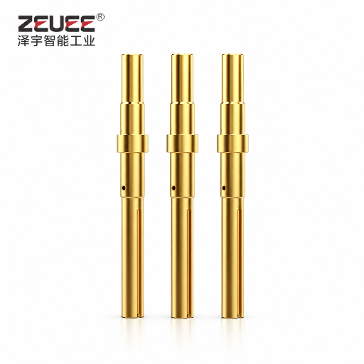
A twist pin isn’t a stamped blade. As described in USPTO patent US7909668B2, a twist-pin interface uses a conductive beam, a barrel, and a bundle of helically wound wires joined by crimping. A related cage-type hyperbolic spring arranges elastic wires into a single-sheet revolving hyperboloid that wraps every mating pin. Many fine wires share the load, so the contact tolerates misalignment and survives high mating-cycle counts, but only while each wire keeps its designed elastic behavior.
That’s why residual stress matters more here than in a chunky terminal. Uneven internal stress across dozens of micro-wires means uneven force, and uneven force means hot spots. Note too that “twist pin” doesn’t always mean copper-beryllium: high-temperature designs such as the Ni-Cr-Ti-Al strand bundle in patent application US20170077617 target service to 260°C precisely because conventional CuBe twist-pins creep at elevated temperature. A correct stress-relief recipe follows the alloy, not the part name.
📐 Engineering Note
For C17200 copper-beryllium, the standard age-hardening cycle is ~315°C (600°F) for 2–3 hours, which precipitates the γ′ phase. Any in-line stress relief must stay safely below that window, or you risk over-aging, losing both strength and the stable contact force you’re trying to protect. Specify the time-temperature profile on the contact drawing, not just “stress relieve.”
The Contact-Force Decay Clock: How Residual Stress Kills a Connector Over Time
Call it the Contact-Force Decay Clock: a predictable countdown from “good contact” to “intermittent failure” that runs whenever residual stress and heat work together. Stress relaxation drives it. A 2025 study of C17200 connector flexure describes it as three stages, initial hardening, a rapid decay phase driven by dislocation annihilation, then slow decay dominated by intergranular slipping. Temperature accelerates the clock: operating a contact near its original age-hardening temperature effectively “undoes” the heat treat, dropping spring force.
The direction is what matters, and it explains material choice. By one set of connector-industry stress-relaxation figures, beryllium-copper contacts hold almost all of their normal force after very long exposure at 105°C, while phosphor bronze relaxes far faster, industry data suggest it can shed a large share of its contact force within roughly 1,000 hours at 105°C. Exact retention depends on temper, stress level, and geometry, so treat published curves as directional. The practical takeaway holds across sources: beryllium copper carries a higher temperature rating (around 125°C versus about 105°C for phosphor bronze) and substantially better relaxation resistance.
⚠️ A field scenario
A defense-electronics integrator chased an intermittent signal in a rugged circular connector that only failed after the unit had been running warm for an hour, on a vibration table. Bench-testing at room temperature showed nothing. Root cause: a batch of contacts that had skipped a proper post-form stress relief: under combined heat and vibration, the spring force had relaxed below the threshold needed to hold a stable interface. Their fix wasn’t a better gold plating, it was restoring the stress-relief step that stabilizes the spring before the clock ever start.
Stress Relief vs Strain Relief: Clearing Up the 1,900-Search Confusion
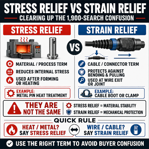
Search “connector strain relief” and you get roughly 1,900 US searches a month, far more than any twist-pin term, and a flood of cord grips and cable boots. That’s a different part of the connector entirely. Strain relief is a mechanical cable-backend feature: a boot, clamp, or grommet that distributes a yank or sharp bend over a larger area so the force never reach the termination, as shown across strain-relief shell patents like US5234358.
Stress relief, by contrast, is a metallurgical process applied inside the contact metal, long before any cable is attached. Even vendor pages and search engines conflate the two terms, which is exactly why specifications go wrong. A simple rule: strain relief protects the cable from the outside world; stress relief protects the contact from itself.
✔ Stress relief (this guide)
- Acts on contact metal (residual stress)
- Thermal / mechanical process step
- Done during contact manufacture
- Protects spring force / reliability
⚠ Strain relief (different part)
- Acts on the cable backend
- Boot / clamp / grommet hardware
- Added at cable assembly
- Protects termination from pull/bend
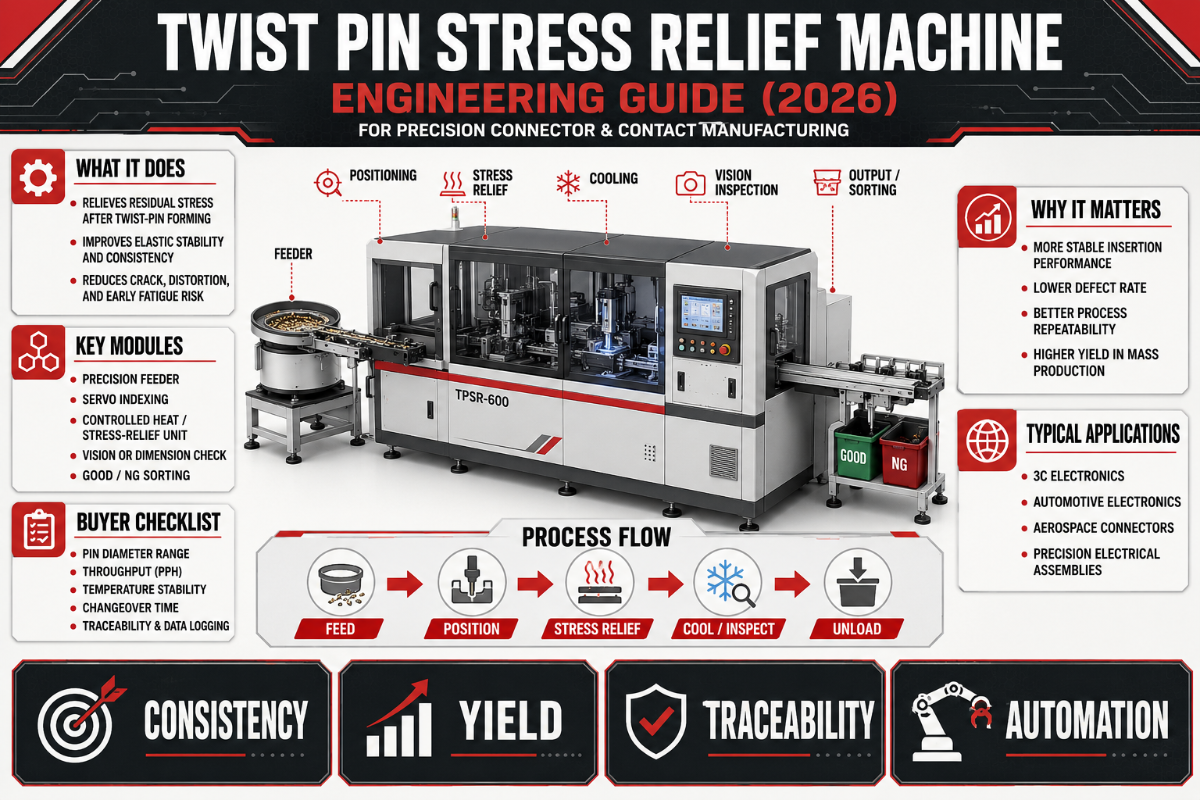
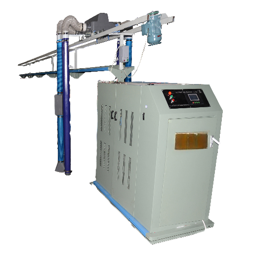
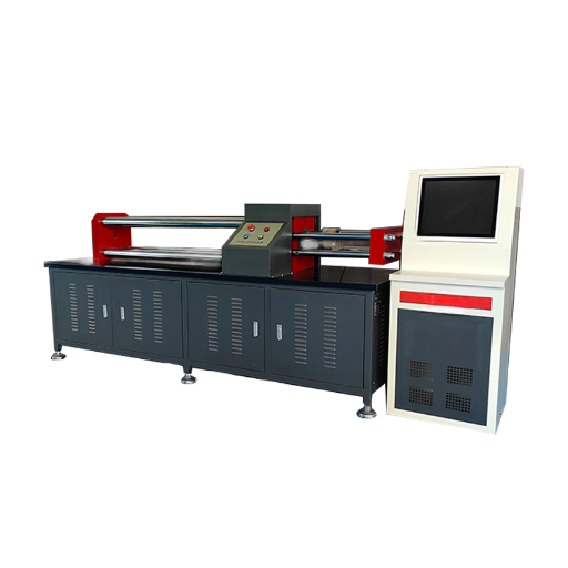
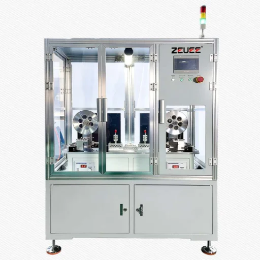
Inside a Stress Relief Machine: Stations, Sensors & Automation
For twist-pin contacts, a “stress relief machine” is usually an in-line thermal station rather than the vibrator-and-accelerometer rig the term evokes. It sits in the production flow after the wires are wound and the cage is formed, holding contacts through a tightly controlled time-temperature profile and then a stable cooldown. Tolerance control is the whole game: the difference between relieving stress and over-aging a copper-beryllium spring can be a few tens of degrees.
Sophisticated lines go further with differential heat treatment. Patent US20030150531A1 describes induction-based, region-specific annealing so the flexible contact region gains stress-relaxation resistance while the anchoring base keep its strength, because uniform oven annealing can improve relaxation but cut overall strength. That trade-off is why a real connector line treats stress relief as local property control, not one global setting. (ZEUEE machine specifics are noted as supplied data; exact recipes belong on the contact drawing.)
⚠️ Important: beryllium handling
Any thermal process on copper-beryllium can generate beryllium-bearing dust or fume. OSHA 29 CFR 1910.1024 lists heat treating and annealing among operations that can trigger beryllium work-area controls. Factor ventilation, monitoring, and PPE into any in-house CuBe stress-relief station, it’s part of the true cost of ownership, not an afterthought.
Standards, Defects & Verification: Measuring Stress You Can’t See
Residual stress is invisible, so verification is where good programs separate from hopeful ones. Two anchors: residual stress itself can be measured by X-ray diffraction per ASTM E915, while the connector-level outcome, does the spring still push hard enough, is checked with contact-force and gauge-retention tests under IEC 60512 (including gauge-retention force, IEC 60512-16-5). Crimp and assembly workmanship for high-reliability contacts is governed by NASA-STD-8739.4.
The Twist-Pin Defect-to-Cause Register
| Defect type (symptom) | Residual-stress root cause | Relief remedy |
|---|---|---|
| Low insertion/withdrawal force at room temp | Spring set from forming, never stabilized | Post-form sub-critical relief |
| Force decays only when hot | Stress relaxation near age temp | Re-spec alloy / lower op temp |
| Intermittent under vibration | Uneven force across micro-wires | Uniform relief + force test |
| Dimensional drift after plating bake | Locked-in stress released by heat | Relieve before final plating |
| Rising contact resistance over months | Slow relaxation, force below limit | Higher-relaxation alloy (CuBe) |
| Cracking at wire bends | Peak residual tensile stress | Stress relief before service |
| Strength loss after relief | Over-aged / over-annealed | Lower temp / differential treat |
| Inconsistent batch behavior | Uncontrolled time-temperature | In-line profile control + logging |
| Creep failure above 150°C | Wrong alloy for service temp | High-temp strand system |
| Corrosion after stainless relief | Sensitizing temperature band | Relieve below 480°C / above 900°C |
Do You Even Need a Stress Relief Step? The 5-Trigger Stress-Relief Necessity Gate
Not every connector program need a dedicated stress-relief station. Run your contact through the 5-Trigger Stress-Relief Necessity Gate: if you answer “yes” to two or more, the step earns its place on the line.
5-Trigger Stress-Relief Necessity Gate
- Service heat: Will the contact run above ~85°C for long periods? (relaxation accelerates)
- Reliability class: Is this aerospace, defense, medical, or EV, where field failure is unacceptable and workmanship follows standards like NASA-STD-8739.4?
- Heavy cold work: Is the contact a tightly wound spring cage with high forming strain?
- Downstream heat: Will the part see a plating bake or reflow that could release locked-in stress?
- Long service life: Is the design rated for 10+ years or a high mating-cycle count?
If you scored 0–1, a correctly aged CuBe contact at modest temperature may not need a separate relief step. Score 2–3 and you should validate with a contact-force test before and after a candidate process. Score 4–5 and stress relief isn’t optional, it’s the cheapest reliability insurance on the line.
💡 A procurement scenario
A buyer sourcing a small run of industrial connectors pushed back on adding a stress-relief station: low volume, room-temperature use, cost-sensitive. Running the gate, the part scored 1, modest cold work, no service heat, short life. The right answer was to skip the dedicated step and instead specify a properly aged copper-beryllium contact. Six months later the same buyer launched an under-hood automotive variant; the same gate scored 4, and the station went in. Same part family, opposite decision, driven by the application, not the brochure.
“The mistake we see most often is treating stress relief as a checkbox. The temperature that relaxes a phosphor-bronze contact will over-age a beryllium-copper one, and the vibratory rig that fixes a steel weldment does almost nothing for a cold-drawn spring wire. The recipe has to follow the alloy and the duty cycle.”
Where Contact-Reliability Engineering Is Heading
Two trends are reshaping how stress relief is specified. First, residual-stress engineering is getting quantitative: 2025 research applied ANOVA and regression to fine-tune vibratory parameters on EN31 steel, and recent peer-reviewed work on vibrational stress relief reports high predictive accuracy (above 90% in published studies) for post-treatment residual stress. Industry direction of travel is data-driven process windows rather than rules of thumb, which will eventually reach connector contact lines.
Second, miniaturization keeps shrinking contact-force budgets while raising operating temperatures in EV and high-density data hardware. That squeezes the margin between “enough force” and “relaxed below threshold,” making the relief step and its verification more important, not less. If you’re planning a 2026 program with elevated service temperature, design the contact-force test and the stress-relief window together from day one, retrofitting reliability after a field return is the expensive path.
Frequently Asked Questions
What is a twist pin stress relief machine?
View Answer
It is a manufacturing station that reduces the residual stress locked into a twisted-wire (hyperboloid) connector contact after it is formed, so the contact holds a stable spring force in service. For copper-beryllium contacts this is typically a controlled sub-aging thermal process, not the vibratory equipment that the same phrase returns in general web searches.
Is stress relief the same as strain relief?
View Answer
No, and confusing them is a common spec error. Stress relief is a metallurgical process applied to the contact metal to relax internal residual stress. Strain relief is a mechanical cable-backend feature — a boot or clamp — that protects the termination from cable pull and bending. One protects the contact from itself; the other protects the cable from the outside world.
Does stress relief change a contact’s dimensions or plating?
View Answer
Done correctly, a sub-critical relief settles dimensions rather than distorting them — that is much of the point. Done at the wrong temperature it can over-age the alloy, soften the spring, or discolor plating. Sequence matters: many shops relieve stress before final plating so a later plating bake cannot release locked-in stress and shift geometry.
How long does a stress-relief cycle take?
View Answer
For copper-beryllium, a typical age/relief cycle is on the order of 2–3 hours at temperature, plus controlled cooldown.
What residual-stress reduction is realistic?
View Answer
It depends on the method and material. Thermal relief on alloy steel reaches roughly 90% relief near 540°C; for copper alloys the goal is less about a headline percentage and more about stabilizing spring force so it does not relax in service. Verify with a contact-force test rather than a single residual-stress number.
Is vibratory stress relief reliable enough for aerospace connectors?
View Answer
For the connector contacts themselves, generally no. Vibratory stress relief works on elastic strains in ductile weldments and large fabrications; its effectiveness on cold-worked precision spring wire is questioned even within the metalworking community. Aerospace contact programs lean on controlled thermal processes and rigorous contact-force verification instead.
Should stress relief happen before or after plating and crimping?
View Answer
As a rule, relieve the base metal stress after forming and before final plating, so a later plating bake cannot release residual stress and distort the finished geometry. Crimped terminations are a separate consideration: the crimp itself introduces local cold work, so high-reliability programs validate the full sequence — form, relieve, plate, crimp — with contact-force and resistance checks at the end rather than assuming each step is independent. The exact order should be proven on your specific contact, not copied from a generic flow.
Specifying a twist-pin contact line and unsure whether stress relief belongs on it?
About This Analysis
This guide was written to untangle a genuinely confusing term: “twist pin stress relief machine” returns vibratory metalworking equipment on most searches, yet the connector-industry meaning is different. We compiled it from connector stress-relaxation data, copper-beryllium heat-treat practice, and USPTO twist-pin patents. Where a specific machine recipe or ZEUEE production figure wasn’t independently verifiable, we used qualified language rather than invented numbers.
References & Sources
- Copper Beryllium Microstructure & Heat TreatmentCopper Development Association
- Stress Relaxation: Mechanisms, Materials and TemperatureConnector Supplier
- US7909668B2, Contact with Twist Pin InterfaceUSPTO
- US20180138623A1, Cage-Type Hyperbolic Spring StructureUSPTO
- US20030150531A1, Differential Induction Heat Treatment of ContactsUSPTO
- 29 CFR 1910.1024, BerylliumU.S. OSHA
- NASA-STD-8739.4, Crimping, Interconnecting CablesNASA Technical Standards
- ASTM E915, Verifying X-Ray Diffraction Residual StressASTM International
- IEC 60512, Connector Test & Measurement MethodsInternational Electrotechnical Commission
- Vibratory Stress ReliefWikipedia
- What Is Stress Relief and Why Perform It?Heat Treat Today