Get in touch with Zeyu lntelligent Industrial Company
A custom assembly machine is a machine engineered around one specific product — its parts, its cycle time, and its tolerance — instead of a catalogue unit the part has to adapt to. Most buyers start the search at the wrong layer. They compare rotary, linear, and robotic architectures before anyone has asked the question that actually decides whether the machine will hold rate: can the part be fed and oriented at all? This guide works from that part-first layer outward — through design for assembly, feeding, fixturing, architecture, the build lifecycle, and the failure modes that sink projects — so you can specify a build that survives a night shift, not just a demo.
Quick Specs: Custom Assembly Machine Engineering Reference
| Placement accuracy (precision builds) | 0.1 mm, within the ISO 9283 robot band (0.02–0.2 mm) |
| Verified throughput (special-purpose models) | 25–45 pcs/min |
| Process-capability acceptance | Cpk 1.33 minimum, 1.67 safety-critical |
| Effectiveness target | OEE 85% world-class benchmark |
| Control stack (typical) | PLC + HMI, servo motion control, pneumatics at 0.4–0.6 MPa, CCD vision |
| Lead time (small cell) | 12–20 weeks; large systems 36–52+ weeks |
| Typical machine mass / footprint | 150–250 kg; ~1500–2100 mm wide |
Updated June 2026. ZEUEE-verified figures are from machines in production since 2005; band figures are industry-typical envelopes.
What Is a Custom Assembly Machine? (And When One Is Justified)
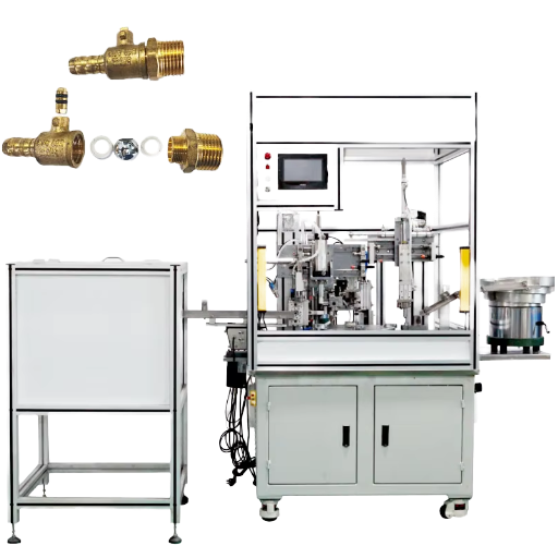
A custom assembly machine is a purpose-built piece of automation equipment that joins, inserts, fastens, dispenses, or tests components for a single product family, engineered to that product’s cycle-time and accuracy targets. It sits between two alternatives: a manual cell, which is flexible but drifts, and off-the-shelf equipment, which is fixed to its own design point and forces your part to adapt to it. Custom machines flip that relationship — the machine adapts to the part.
Economics, not engineering, usually triggers a custom build. Direct manual labour commonly runs 30–50% of a production budget with no path to scale, and the U.S. median wage for assemblers and fabricators is about $38,920 per year ; fully burdened at a 1.3–1.5× multiplier, one operator costs roughly $50,000–$58,000. When a standard machine would need so many modifications that you are effectively paying custom prices for a compromised result, or when your tolerance or cycle-time target sits outside the catalogue envelope, a custom build is the honest answer. ZEUEE’s own custom assembly machine program exists for exactly that moment.
💡 Terminology
“Custom assembly machine”, “custom automated assembly machine”, “special-purpose machine”, and “non-standard automation system” all describe the same custom automation idea at different scales. One single-station press is a machine; several stations linked by an indexing table or transfer track become an assembly cell or assembly line; a custom machine builder engineers any of this assembly machinery around your part. Custom automated lines and stand-alone automation systems differ only in how many of these subsystems they tie together.
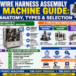
The Anatomy of a Custom Assembly Machine: 6 Core Subsystems
Every custom assembly machine, from a cosmetics nozzle line to a connector inserter, is built from the same six subsystems. Reading a quote means reading these six — because a weakness in any one caps the whole machine. This 6-Subsystem Anatomy Teardown maps each one to its job and to what breaks when it is under-engineered.
| # | Subsystem | Function | Typical components | If it is wrong |
|---|---|---|---|---|
| 1 | Base & transport | Moves the part between stations | Rotary dial, linear transfer, indexing table, walking beam | Cycle-time ceiling set too low |
| 2 | Part feeding & presentation | Singulates and orients incoming parts | Vibratory bowl feeder, linear feeder, flexible/vision feeder | Jams, misfeeds, the #1 downtime source |
| 3 | Fixturing & tooling | Locates and holds the part to a datum | Nests, clamps, quick-change tooling | Position error, stack-up, scrap |
| 4 | Process / joining stations | Does the actual work | Servo press-fit, screwdriving, dispense, weld, heat-stake | Weak joints, bad shots, rework |
| 5 | Vision & inspection | Verifies before the part advances | CCD machine vision, presence/absence sensors, gauging | Defects escape to the customer |
| 6 | Controls & safety | Sequences everything; keeps operators safe | PLCs, HMIs, servo motion control, light curtains, interlocks | Unexpected motion, interface faults, stoppages |
Subsystem framework: ZEUEE engineering; robot-safety hazards per OSHA Technical Manual.
Two of these are routinely under-respected at the quoting stage. Feeding (subsystem 2) is treated as a commodity bolt-on, and controls and safety (subsystem 6) are treated as wiring. Both assumptions are where projects quietly fail. OSHA’s robotics safety manual attributes unexpected robot reactions to programming, interfacing, peripheral-equipment, and control errors — hazards that have nothing to do with the mechanical assembly and everything to do with subsystem 6. A custom build is only as good as the weakest of the six.
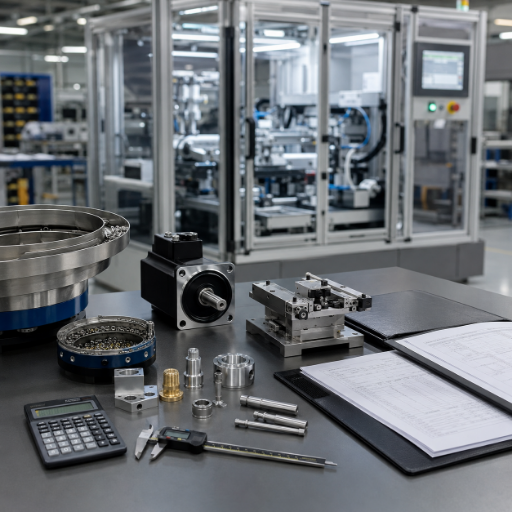
Design for Assembly (DFA): Why Most Automation Problems Start at the Part
What is design for assembly?
Design for assembly (DFA) is the practice of simplifying a product so it is cheaper and more reliable to put together, and, for automation, so a machine can handle it at all. Its single most powerful principle is part-count reduction: every component you eliminate removes an assembly step, a feeder, a fixture, and a failure mode.
Boothroyd and Dewhurst formalized the method, and the U.S. Department of Energy’s DFMA training module makes the same point: assembly cost reduction lowers overall manufacturing cost, much of it locked in at the design stage, not on the machine.
Here is the part everyone underestimates. A trade-press piece in ASSEMBLY Magazine states it plainly: engineers must design parts specifically to be handled and fed by robots, vibratory bowls, and other automated equipment. What a person assembles with two hands and a pair of eyes can be impossible for a machine to feed — because the machine has neither the dexterity nor the judgement to recover from a part that tangles, nests, or has no feature to orient against.
The Feedability Gate — a 3-question part screen
Before you spec a single station, run the part through three questions. Fail any one, and the cheapest fix is the part, not the machine.
- Can it be singulated? Can one part be separated from a bulk supply without two parts arriving stuck together or interlocked?
- Can it be oriented by a feature, not an eye? Is there an asymmetry — a notch, a flat, an off-centre hole — a feeder can register against to put every part the same way up?
- Can it be presented repeatably? Will it sit in a nest the same way every cycle, or does it rock, nest inside its neighbour, or tangle?
Consider a real pattern. A medical-device team in Ohio specified a 6-station machine for a snap-together housing, then discovered in debug that the two halves nested inside each other in the feeder bowl about one time in forty. No control logic fixes that; the parts physically interlock. Its cure was a 0.4 mm rib added to the moulding tool — a part change, made after the machine was half-built, that a Feedability Gate review would have caught in an afternoon. Designing the part to be fed is almost always cheaper than designing a feeder to tolerate a difficult part.
📐 Engineering Note
Give every automated part a deliberate orientation feature and a lead-in chamfer of at least 0.5 mm on mating edges, and an orientation feature of 1–2 mm a feeder can register against. Asymmetry is a feature, not a defect: a part that is symmetrical in every axis cannot be oriented and must be hand-loaded. Where symmetry is unavoidable, make the part fully symmetrical so orientation does not matter — the two ends of the DFA spectrum both work; the middle does not.
Part Feeding & Presentation: The #1 Cause of Assembly Machine Downtime
If there is one rule that separates engineers who have run custom machines from those who have only bought them, it is this — call it The Feeding-First Rule: the joining process almost never decides whether a line holds rate; feeding does. Feeders are mechanical, tuned, and unforgiving. Vibratory bowl feeders develop dead spots, spring fatigue, and tooling wear; a single jam stops the whole machine while every downstream station sits idle. Even a press station that runs flawlessly is worthless if the feeder upstream starves it.
Choosing a feeding method is therefore one of the highest-impact decisions in the whole build. Below, the table maps the common methods to part size, rate, and changeover so you can match presentation to the part instead of defaulting to a bowl.

| Feeder type | Part size | Typical rate | Changeover | Best for |
|---|---|---|---|---|
| Vibratory bowl feeder | <100 mm, rigid | up to 300/min | Hard (retooled bowl) | High volume, stable part |
| Centrifugal feeder | 3–30 mm, round | high, quiet | Hard | Gentle, high-speed feeding |
| Inline / linear feeder | pre-oriented, <60 mm | buffer-dependent | Medium | Buffering after a bowl |
| Step feeder | 10–80 mm, fragile | moderate | Medium | Parts that bruise in a bowl |
| Magazine / stick feeder | stacked, ≤50 mm | indexed | Easy | Pre-stacked parts |
| Tape-and-reel feeder | SMD, <10 mm | high | Software | Electronic components |
| Flexible / vision-guided feeder | 2–120 mm, mixed | lower, flexible | Minutes (software) | High-mix, low-volume |
| Robotic bin-pick | random bulk, ≤200 mm | lower | Software | Unstructured supply |
| Tray / pallet load | delicate, presented | manual-paced | Easy | Low volume, high value |
Rate and changeover are envelopes; the right type depends on part geometry and your Feedability Gate result.
What is a vibratory bowl feeder?
A vibratory bowl feeder is a tooled bowl that uses controlled vibration to walk parts up a spiral track, where mechanical tooling such as wipers, cut-outs, and air jets rejects any part not in the correct orientation, returning it to the bowl. It is the workhorse of high-volume feeding because it is fast and cheap to run.
But it is dedicated: the bowl is tooled to one part, so a new product means a new bowl. That dedication is exactly why the industry is shifting toward flexible feeding for high-mix work, a trend examined in the outlook section below.
Flexible feeding is worth understanding because it is now patented, mature technology, not a lab demo. Flexible feeders spread parts on a backlit surface, photograph them, and let a robot pick only the parts a vision system confirms are correctly oriented — an approach described in US Patent 6,056,108 for an impulse-based flexible parts feeder and built on by 3D vision-guided picking. ZEUEE pairs CCD vision inspection systems with feeding so a misoriented or missing part is caught before it reaches a press, not after.
Fixturing, Tooling, and Error-Proofing (Poka-Yoke)
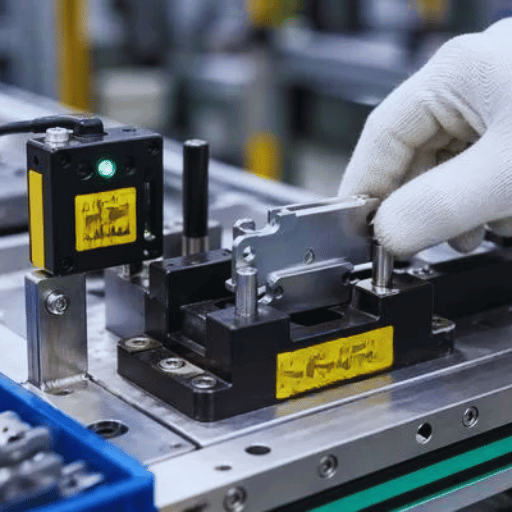
Once a part is fed, it has to be held — precisely, repeatably, and in a way that physically refuses to accept a wrong or wrongly-oriented part. That is the job of fixturing, and it is where mechanical design and quality engineering meet. Each fixture locates the part against a datum (a defined reference surface or feature) and clamps it so every operation happens in a known position.
Get the datum scheme wrong and tolerances stack up across stations until good parts measure bad. Whether a part can be located and held repeatably is part of its manufacturability — the kind of feasibility NIST’s automated manufacturability analysis work treats as an engineering question, not an afterthought.
What a fixture does best is mistake-proof the process — poka-yoke. Done well, it is mechanical, not electronic: a nest shaped so a part can only seat one way, a pin that blocks a reversed component, a pocket that a wrong variant will not drop into. The part fails to load rather than loading wrong, so the error is impossible instead of merely detected. This is far cheaper and far more reliable than catching the same mistake later with a sensor.
For a machine that runs a product family, quick-change tooling lets one base machine accept several nests, trading a higher up-front tooling cost for changeover measured in minutes instead of hours.
📐 Engineering Note
Use one datum scheme per part across every station — locate from the same features the part’s drawing is dimensioned from (hold locating datums to about ±0.05 mm), so the machine and the inspection report speak the same language. Where a part is nearly symmetrical, add a physical poka-yoke feature (an offset pin or asymmetric pocket) so a reversed part cannot seat. Design the fixture so wrong is impossible, not just visible.
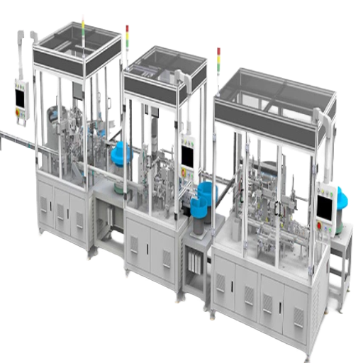
Matching Architecture to Volume: How Takt Time Drives the Build
Only now — after the part, the feeding, and the fixturing are understood — does architecture become a useful question. And the variable that answers it is takt time. Takt time is the available production time divided by customer demand — the beat the line must hold to meet demand. It is the bridge between a business number (how many you need to ship) and an engineering number (how fast each station must run).
Worked example — the Volume-to-Architecture Curve
Say you need 250,000 units a year, on one 8-hour shift (28,800 seconds), 240 working days, so daily demand is about 1,042 units.
Takt time = 28,800 s ÷ 1,042 units ≈ 27.6 s/unit.
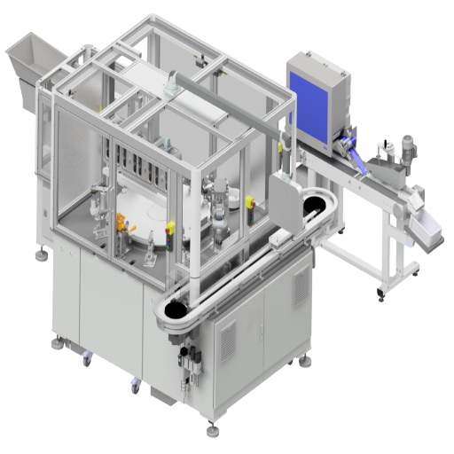
A 27.6-second beat is comfortably within reach of a robotic cell (10–30 s/cycle), so you do not need the speed of a rotary dial. But raise demand to 1.5 million units a year and takt falls below 8 seconds — now only a parallel-station rotary or linear transfer machine can keep up, and a single robot physically cannot. Takt, not preference, picks the architecture.
That trade-off is consistent across builds: rotary dials win on raw speed and footprint for stable, high-volume small parts but run at the speed of their slowest station; linear transfer wins when you have many operations or long-dwell steps such as curing or leak testing, because stations keep independent timing; robotic and collaborative cells win on flexibility and short changeover when the mix is high and volumes are lower. Many real machines are hybrids — a fast servo-indexed core with a robot for feeding (3D vision-guided picking of the kind described in US Patent 8,095,237) and a robot-integration cell at the flexible end. To run your own volume and cost-per-part numbers against each architecture, ZEUEE publishes an architecture-fit and cycle-time estimator, and the broader automated assembly machines range shows where each platform fits.
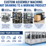
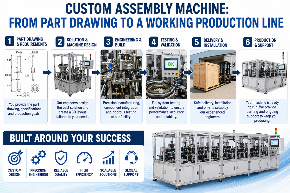
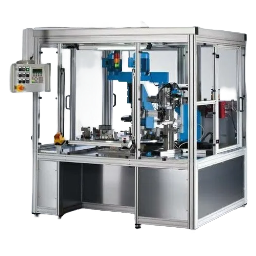
From Spec to Runoff: How a Custom Assembly Machine Gets Built
A custom assembly machine has no catalogue; it has a process. Understanding that process tells you what information a builder needs from you and where the risk lives. Good custom machine builders and systems integrators run the same engineering lifecycle whether the machine is a single press or a turnkey line.
| Stage | Key deliverable | Typical duration |
|---|---|---|
| 1. Requirements (URS) | Part drawings, volumes, cycle time, tolerances, quality criteria | 1–3 weeks |
| 2. Concept & DFM review | Architecture, station plan, Feedability Gate, manufacturability feedback | 2–4 weeks |
| 3. Detailed design | Mechanical, controls, and vision design; PLC/HMI architecture | 4–10 weeks |
| 4. Build & integration | Fabrication, assembly, wiring, programming | 6–20 weeks |
| 5. Debug | Tuning feeders, vision, motion; first good parts | 2–6 weeks |
| 6. FAT & runoff | Acceptance against agreed cycle time, accuracy, Cpk/OEE | 1–2 weeks |
Your real protection is the Factory Acceptance Test. Done right, a documented FAT proves the machine against the tolerance written into your specification before it ships — not after it lands on your floor. Set the acceptance criteria early: a process capability of Cpk 1.33 is the minimum acceptable level (about 63 defects per million), and Cpk 1.67 is the safety-critical threshold near Six Sigma that aerospace and automotive buyers demand. Pair that with an OEE target (85% is the world-class benchmark) and a positioning check benchmarked to ISO 9283, and you have an acceptance test with teeth.
“On the pin-insertion machine we hold 0.1 mm because the CCD station checks position before the servo drives the pin, and a missing-pin detector stops the cycle rather than passing a bad part downstream. We would rather lose one index than ship a connector that fails at the customer’s board test.”
— ZEUEE Engineering Team, connector assembly build notes
Evaluating a custom machine builder
What separates a full-service custom machine builder from a parts supplier is how much of this it does in-house. One systems integrator that designs and builds custom machinery — owning mechanical design, controls, vision, and software as one team — removes the handoffs where complex production projects usually slip. Building custom equipment this way means the team that designed the assembly process also debugs it.
When you evaluate a builder, look for proof that they build custom assembly machines and turnkey assembly systems rather than reselling them: machines designed and built to a customer’s spec, real engineering support after runoff, and genuine expertise in assembly across various industries.
Strong custom automation partners offer build-to-print and custom machine-building services, multi-station and robotic systems, closed-loop control systems, and automation solutions tailored to your project requirements — not a fixed catalogue. That depth of automation technology and production capabilities is what turns a list of customer requirements into a production system that holds product quality, lifts productivity, and meets your production needs.
ZEUEE develops custom automated assembly machinery and turnkey assembly automation systems — equipment manufacturing for medical device manufacturing, food and beverage, consumer product, and electronics lines — so the same automation experts who provide solutions at the concept stage stand behind the machines and systems at runoff. These custom assembly machines and the broader manufacturing systems around them sit inside a wider industrial automation push — where the point is productivity and efficiency on real parts, not automation for its own sake.
Why Custom Assembly Machines Fail (and How to De-Risk the Build)
Custom machines rarely fail for one reason, and treating any single subsystem as the whole story is itself a failure mode. In practice, builds underperform across five domains — and the discipline is to pressure-test all five before signing, not to fixate on the one you already understand.
Five failure domains — the de-risking checklist
- ✔The part isn’t designed to be fed. The most overlooked domain. If the part fails the Feedability Gate, no machine recovers it. Fix the part first.
- ✔Controls and safety integration. Per OSHA, unexpected robot motion comes from programming, interfacing, and control errors — design interlocks, light curtains, and safe states as engineering, not an afterthought.
- ✔No graceful error recovery or interoperability. Any machine that cannot detect a misfeed and recover — or cannot talk to your MES — stops being automated the first time something goes wrong. Specify fault handling and the data interface.
- ✔Scope creep without change control. Scope creep is a leading cause of overruns; general project data shows 85% of projects with scope creep exceed their budget, at an average 27% overrun. Use a staged contract with formal change orders.
- ✔Under-specified incoming-part tolerance. A machine built to a tolerance the supplied parts don’t actually hold will run scrap at full speed. Tie incoming-part limits to the spec.
All five share one pattern: the most expensive mistake in assembly automation is committing to an architecture before validating the part, the controls plan, and the acceptance criteria — and discovering the gap after the machine is built. Even a short, honest concept-and-DFM review is the cheapest insurance you can buy. ZEUEE writes cycle-time, accuracy, and yield criteria into the contract before build for exactly this reason — see the custom assembly machine page for how that acceptance discipline is structured.
Industry Outlook: Where Custom Assembly Automation Is Heading (2026 and Beyond)
Honestly, the near-term picture is mixed, and that matters for how you time a build. The IFR’s World Robotics 2025 report shows industrial-robot installations actually fell in Europe, the Americas, and the United States in 2024 — so the story is not a simple upward line. Underneath that cyclical dip, though, the structural driver is unchanged: labour scarcity and reshoring keep pushing automation into work it used to skip, especially high-mix, low-volume production that fixed feeders never suited.
Two shifts follow from that driver, and both change what you should specify. First, vision-guided flexible feeding is displacing part-dedicated bowls for high-mix lines, because a software changeover beats a retooled bowl when products turn over quickly.
Second, controls are getting smarter — “physical AI” and learn-from-demonstration methods, now appearing in granted patents such as US 2023/0086122, are starting to cut the programming and changeover cost that historically made low-volume automation uneconomic. So, the practical takeaway for a 2026 RFQ: ask vendors for changeover time per product variant and for the machine’s error-recovery and data-interface behaviour — not only peak pieces per minute. Yes, the market is large and growing over the decade, but that is background; the decision is about flexibility, and flexibility is something you specify, not something you wait for.
FAQ: Custom Assembly Machine Questions
Q: What is a custom assembly machine?
View Answer
A custom assembly machine is automation equipment engineered around one specific product, its parts, cycle time, and tolerance, rather than a catalogue unit your part must adapt to. It combines feeding, fixturing, joining or dispensing, vision inspection, and PLC controls into one machine tuned to your assembly. Builders reach for one when off-the-shelf equipment would force the part to adapt to the tool, or when manual labour grows too large a share of cost to scale.
Q: What is the difference between a custom assembly machine and an automated assembly machine?
View Answer
An automated assembly machine is any machine that assembles parts without a manual operator standing at each step. Custom means the machine was engineered for your particular product and assembly sequence rather than sold as a standard catalogue model. Almost every custom assembly machine is automated, but plenty of automated machines are standard rather than custom.
Q: How do I know if my part can be automated?
View Answer
Your part is automation-ready if it passes the Feedability Gate. It must be separable from bulk one at a time, orientable by a physical feature rather than a human eye, and presentable to a nest the same way every cycle. If it tangles, nests inside itself, or has no asymmetry a feeder can register against, it will fight automation. The fix is usually a small design change, a rib, flat, or notch added before the machine is built.
Q: What is the most common reason a custom assembly machine underperforms?
View Answer
Feeding, far more often than the joining process. A press or dispense head that works perfectly still sits idle every time the feeder upstream jams or misfeeds. Close behind feeding are controls and safety integration faults and the absence of graceful error recovery.
Q: How long does a custom assembly machine take to design and build?
View Answer
Small cells typically run 12 to 20 weeks from order to runoff; large turnkey systems run 36 to 52 weeks or more, even from domestic builders, because each station is built and debugged in sequence. See the custom assembly machine page for lead-time detail.
Q: Rotary, linear, or robotic, which architecture is right for me?
View Answer
Start from takt time, the available production time divided by demand. A beat under about 8 seconds usually needs a parallel-station rotary or linear transfer machine, because a single robot physically cannot keep up. A beat of 10 to 30 seconds suits a robotic cell, which also wins when product mix is high and changeover has to be fast. Many real builds are hybrids, so run your own numbers through ZEUEE’s architecture-fit estimator.
Q: What standards apply to assembly-machine acceptance?
View Answer
Acceptance usually references process capability (Cpk 1.33 minimum, 1.67 for safety-critical work) and OEE (85% world-class), proven at a Factory Acceptance Test. Robot positioning is benchmarked to ISO 9283, so agree the exact figures before build and write them into the contract.
About This Guide
This guide reflects how ZEUEE engineers custom assembly machines for connector, terminal, nozzle, and consumer-product lines — work running since 2005 across more than 30 countries, backed by 150+ patents and ISO 9001:2015 certification. The part-feeding, fixturing, and acceptance figures here come from machines ZEUEE has shipped, not from a brochure. Reviewed by the ZEUEE technical team.
References & Sources
- Design for Manufacturing and Assembly (Module 3D) — U.S. Department of Energy
- Automated Manufacturability Analysis: A Survey — NIST
- Occupational Employment & Wages, Assemblers and Fabricators (51-2090) — U.S. Bureau of Labor Statistics
- Technical Manual, Industrial Robots and Robot System Safety — OSHA
- ISO 9283:1998 — Manipulating industrial robots, performance criteria — ISO
- Takt Time — Lean Enterprise Institute
- Designing Parts for Automation — ASSEMBLY Magazine
- US Patent 6,056,108 — Impulse-based, flexible parts feeder — USPTO
- World Robotics 2025, Industrial Robots Executive Summary — International Federation of Robotics