Get in touch with Zeyu lntelligent Industrial Company

How Handle Assembly Machines Work—and How to Validate One

ENGINEERING GUIDE · Updated October 14, 2026
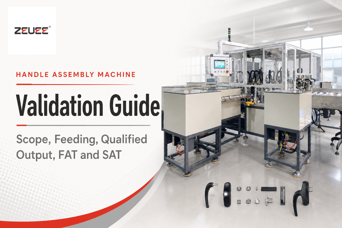
A handle assembly machine is used for handle assembling: it feeds, orients, joins, checks, and transfers handle components or attaches a finished handle to another product, and a handle fitting machine requires the same defined input and output boundary. The useful buying question isn’t “How fast is the machine?” The useful buying question is “Which handle family, input condition, joining result, and recovery state has that output rate actually proved?”
Quick answer
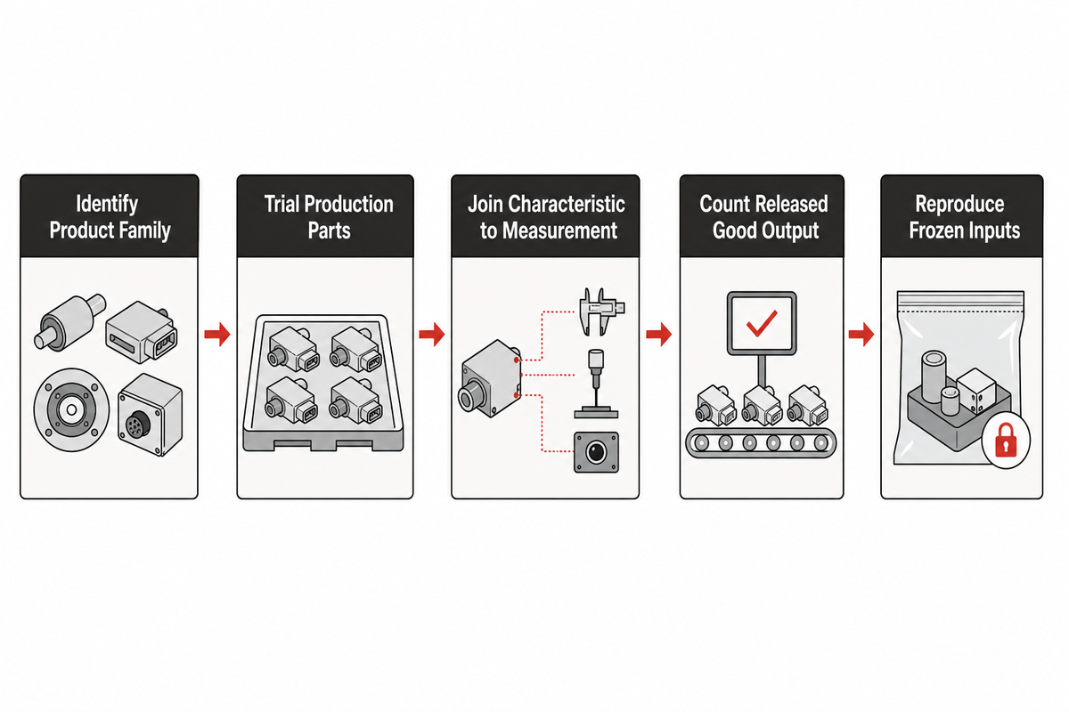
First, identify the product family. Next, trial real production parts. Then connect every joining characteristic to a traceable measurement, count only released good output, and make FAT and SAT reproduce the same frozen inputs. That route exposes risk earlier than a polished demonstration built around one hand-picked sample.
- The machine name may describe three different boundaries: handle making, handle subassembly, or attachment to a host product.
- There is no public universal FAT sample count for every handle assembly application.
- A camera confirms only the visible characteristics defined in its inspection plan.
- Qualified output is good released units per agreed time window, not the fastest station cycle.
- Part presentation must be proved with production-representative parts, including the approved geometry, finish, packaging history, and variant mix.
What Does a Handle Assembly Machine Actually Do?
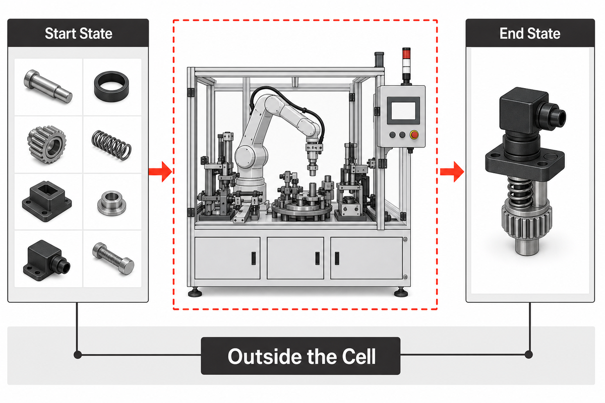
The market label disguises various production duties. One system may form and join a multi-part handle. Another may assemble a spring, grip, pin, or latch into a handle mechanism. A third may receive a complete handle and attach it to a bucket, appliance, package, case or other product. A published patent outlines one aluminum-handle carousel with multiple feeds, lubrication, adhesive, fastening, and discharge; it isn’t universal. This information is background for other applications, not every system.
Write the boundary as a start state and an end state. For example, “loose grip, two end pieces and pins in; checked handle subassembly out” or “complete handle with host product, attached and inspected out.” Also state what’s outside the cell, for example, upstream forming, cosmetic cleaning, destructive testing, packing and/or palletizing. The boundary prevents two suppliers from quoting different duties under the same machine name.
This article performs the definition and validation. For other functions, such as model selection, commercial configuration or RFQ path for an automatic system, use ZEUEE’s automated assembly machine overview and the dedicated solution page linked at the end of this article.
Define the Handle Family Before You Define the Machine
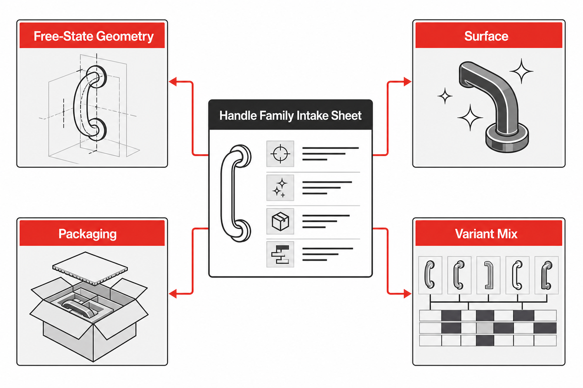
“Plastic handle” or “metal handle” is too broad for automation. A bucket handle made from formed wire, a molded grip, and a paint roller handle can all carry the same label while presenting completely different feeding and joining behavior; a published handle-assembly patent illustrates how application-specific those station duties can be. Two handles that fit the same product can behave differently in a feeder because their free-state shape, stiffness, mass distribution, flash, coating, static, or tendency to nest is different. Storage matters too. Trade-engineering examples show that molded parts can deform under packaging load and later cause a feeder failure even though freshly made samples run cleanly.
The Handle Family Intake Sheet should be completed prior to concept approval. It’s an input-risk map, not a supplier’s model table.
| Input to freeze | What to record | Risk it reveals | Evidence to attach |
|---|---|---|---|
| Revision | Drawing and change level | Old tooling or recipe used on a new part | Controlled drawing |
| Free-state geometry | Span, bow, end angle, asymmetry | Bridging, nesting, wrong orientation | Dimensioned sample set |
| Stiffness | Expected variation and temperature state | Deflection at pick or insertion | Test method and limits |
| Surface | Texture, coating, gloss, cosmetic zones | Scuffing, glare, poor grip | Approved appearance standard |
| Mass and balance | Nominal and tolerated variation | Unstable presentation or pick | Measured samples |
| Flash or burr | Location and acceptance boundary | Jams or false seating | Good/bad boundary samples |
| Packaging | Layering, bagging, separators, part level | Tangling or deformation | Production pack photos |
| Dwell history | Storage time and environment | Shape drift missed by fresh samples | Aged sample lot |
| Variant mix | Batch size and change frequency | Excess changeover or dedicated tooling | Production schedule |
Freeze Inputs Before Freezing the Machine Design
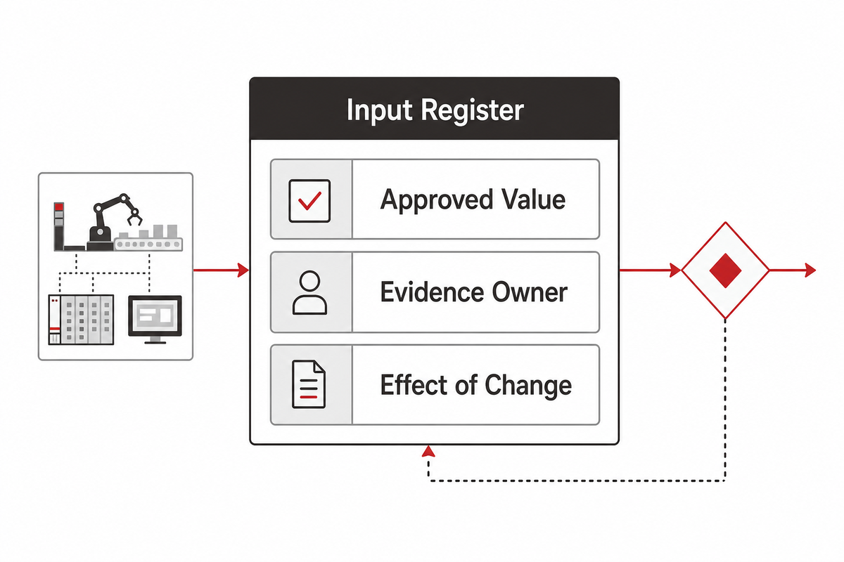
A design freeze should cover more than just a handle sketch. It should cover the revision level of the handle and the mating part, assembly sequence, presentation of upstream parts, method of joining, inspection / reject rules, product change rules, site constraints, utility connections, and data interfaces. If a rule is “to be determined,” record which design decision it blocks.
An input register should identify the input, its approved value, evidence owner, and effect of changing the value. For example, an approved coating change may alter bowl-track friction, gripper contact, or image contrast. A new host-product datum may affect insertion alignment and the inspection fixture. The machine concept shouldn’t absorb changes silently.
Separate facts from assumptions. A drawing is evidence of intended geometry; it isn’t evidence of bulk feeding behavior. A supplier cycle simulation is evidence of a planned sequence; it isn’t evidence of qualified output. A gauge can be part of a measurement chain, but NIST’s traceability guidance explains that metrological traceability applies to measurement results and, by itself, doesn’t establish fitness for the intended decision or freedom from mistakes.
Choose Part Presentation by Observed Part Behavior
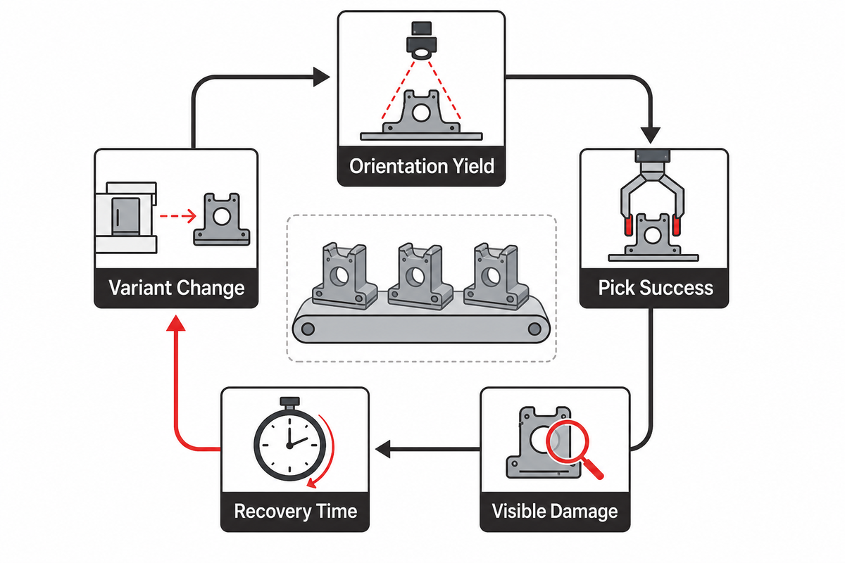
A stable, high-volume geometry can suit a dedicated vibratory or centrifugal feeder. A tray feeder can protect cosmetic parts, but it moves complexity into dunnage and replenishment. Flexible feeders can help when variants change frequently, yet they still depend on part separation, imaging, pick access, recirculation, and a recovery plan. Trade coverage of flexible feeding for assembly makes this a product-mix decision, not a simple “newer is better” choice.
Presentation Proof Trial
Run the trial with production-representative parts, including tolerated geometry, normal packaging, storage history, surface condition, and the least cooperative approved variant. The following data should be recorded:
- Lot identity, revision, and packaging, storage time and sample selection.
- Starting part level and replenishment method;
- orientation yield, recirculation count, pick success, and visible damage;
- jam location, detection method, containment, and recovery time;
- Behavior after a planned stop; low-part condition and restart; and variant change.
- Which settings are product recipes and which require mechanical change.
Don’t use a single run to set a universal feeder rate. The trial should support the sample, as well as the setup and time window. The trial should also define what would make the conclusion invalid.
Match Joining, Datums, and Verification
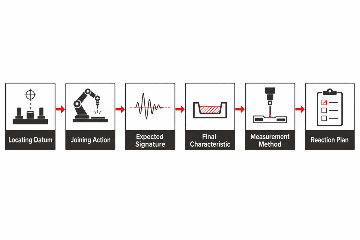
Start with product characteristics instead of sensor catalogs. For each joining step, specify the locating datum, action, expected signature, final characteristic, measurement method, and reaction for a missing or failed measurement.
| Joining task | Useful process signal | What it can indicate | What it does not prove alone |
|---|---|---|---|
| Press fit | Force–distance curve | Event occurred within a defined window | Long-term retention for every material condition |
| Screw fastening | Torque–angle trace | Fastener event followed the set rule | Hidden thread condition or future loosening |
| Pin insertion | Position and force | Insertion reached a defined state | All concealed damage |
| Adhesive dispense | Pressure, flow, or bead image | Defined dispense indicators were present | Cure strength without a suitable test |
| Visible component | Camera presence check | Defined feature is visible in the image | Hidden seating, bond, or retention |
| Orientation | Vision or keyed fixture | Defined pose matches the rule | Every downstream functional requirement |
| Latch function | Travel, force, or functional probe | Observed motion meets the test rule | Lifetime durability |
| Cosmetic surface | Controlled imaging | Defined visible defects under set lighting | Defects outside the trained or specified class |
| Released product | Linked result record | Required checks were recorded | Correctness if the decision rule is inadequate |
A challenging inspection may call for traditional vision systems, photometric methods, functional gauging, or even a human decision; verification-method comparisons show that no single method can always win. A “pass” count becomes qualified output only when the characteristic, measurement capability, decision rule, and reaction plan are fit for purpose.
Translate Cycle Time into Qualified Output
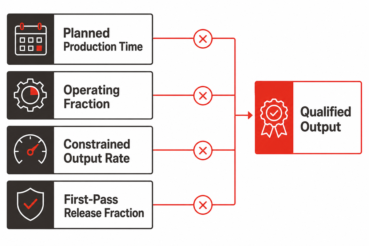
Nominal cycle time is the planned duration for a constrained process step. It doesn’t include all stops, re-starts, process starvation, changeovers, rejects, quarantines, and holds. A useful output promise states its clock boundary and counts only product that meets the agreed release rule.
4-Factor Qualified Output Rule
Expected output equals planned production time multiplied by operating fraction, constrained output rate, and first-pass release fraction.
This resembles the public availability, performance, and quality separation in the OEE calculation structure, and retains an explicit buyer’s release definition.
Assume a planned window of 450 min, a 90% operating fraction after stops, a constrained rate of 12 units/min while running, and a 98% first-pass release fraction.
450 min × 0.90 × 12 units/min × 0.98 = 4,762.8 units/shift, or about 4,762 released assemblies per planned shift before any agreed rounding rule.
If the fastest station’s ideal cycle suggests 5,400 units/shift, the 637-unit gap isn’t “lost in the math.” It’s the hidden bottleneck map: stops account for 540 units/shift, and first-pass release loss removes about 97 units/shift from the operating output. Replace the assumptions with witnessed values, state whether changeover is inside the clock, and keep quarantined pieces out until their release decision is complete.
Stabilize the Process Before You Claim Capability
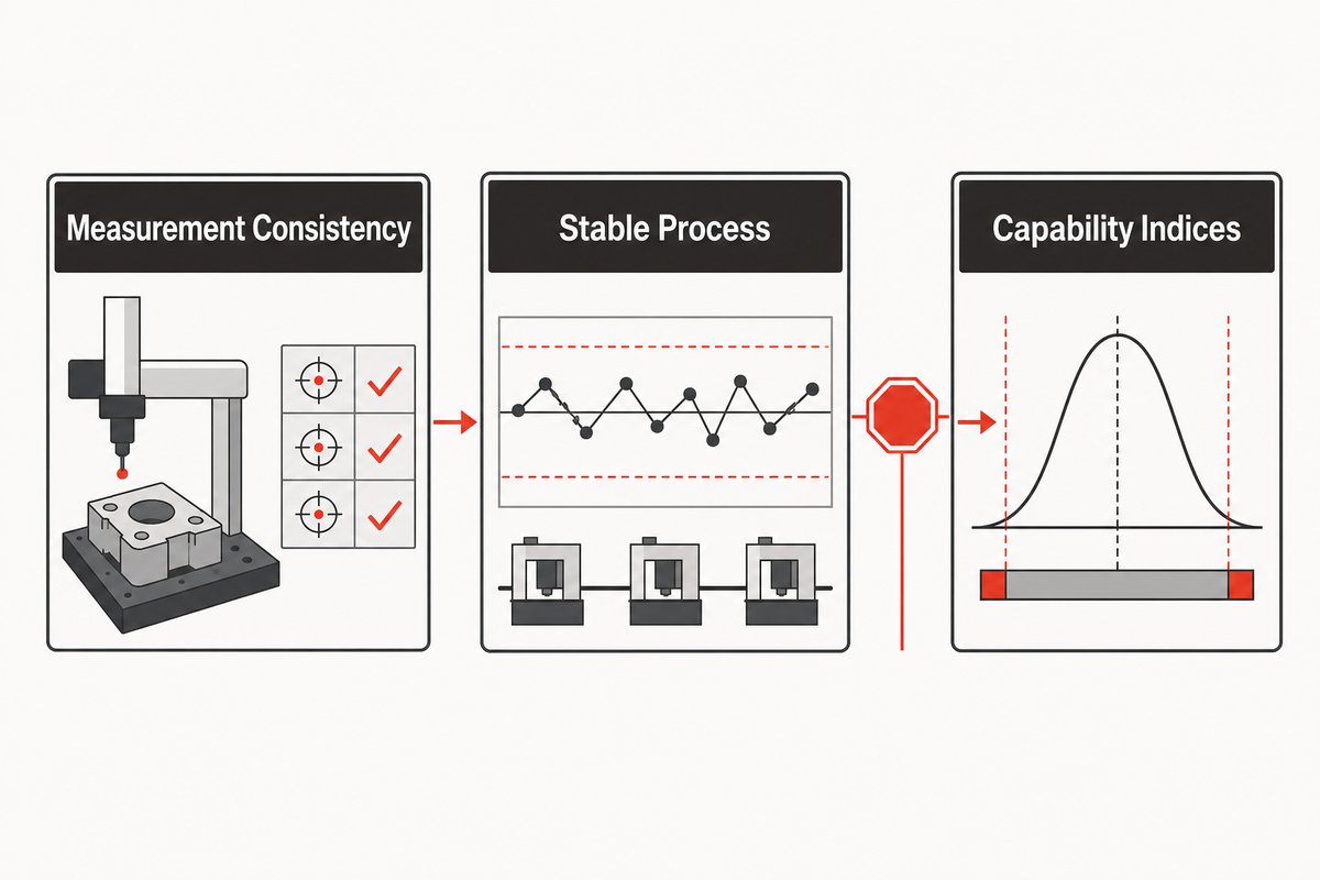
A capability number isn’t a substitute for a stable process. First, check whether the measurement of the characteristic behaves in a consistent manner for the intended analysis. Second, check whether the chosen model fits the data. Common capability indices may rely on independent observations and distribution assumptions; a neat Cpk value does not erase those conditions.
“The process must be stable before we can attempt to assess the capability.”
NIST’s process capability guidance elaborates both the in-control process requirement and assumptions of common capability indices. Sample sizes included in the handbook are to illustrate the assumptions and aren’t to be used to determine machine acceptance. Agree on the characteristic, subgroup logic, study window, treatment of changeovers, measurement uncertainty, and response to instability before setting a project threshold.
Release Each Variant as One Controlled Configuration
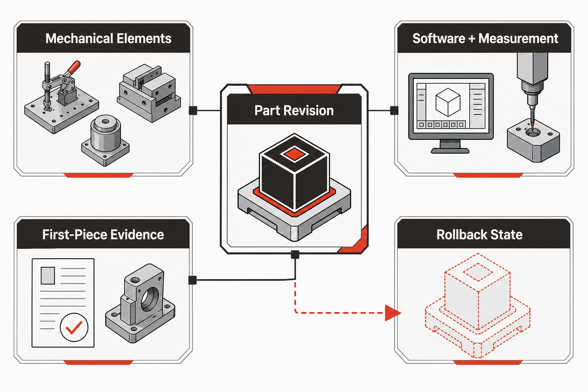
A recipe number by itself doesn’t indicate that the cell is ready for a handle revision. The released configuration should bind the part revision to feeder tooling, grippers, nests, joining programs, gauge setup, vision files, limits, reject routing, label or record fields, and first-piece evidence.
Use a variant release card to make five decisions: what changed; which risk-assessment assumptions that change can affect; which mechanical, software, and measurement elements change with it; what evidence releases the first piece; and how an operator confirms the active configuration. Show the rollback state for a release that fails.
Here, the Handle Family Intake Sheet becomes the change-control record. A finish revision may require a presentation trial and lighting check, without changing the joint program. A geometry revision may change the nest, datum, force-distance window, and camera region all at the same time. Treat these as one configuration change.
Build FAT and SAT Around Evidence, Not a Demo
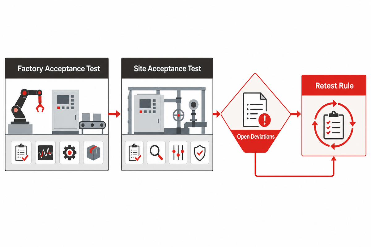
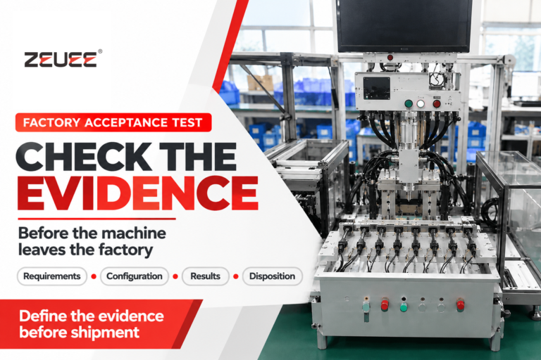
A factory acceptance test determines whether the agreed machine and product configuration performs as designed in the factory environment. A site acceptance test asks whether that accepted configuration still performs after installation with site utilities, interfaces, operators, materials, and upstream or downstream equipment. Both tests should use the same controlled product definition and record clearly what has changed between tests.
| Witness item | Evidence | Owner | Decision boundary |
|---|---|---|---|
| Product identity | Revision and lot records | Buyer quality | Representative of approved family? |
| Input condition | Packaging and storage record | Buyer production | Matches normal supply state? |
| Configuration | Tooling, recipe, software versions | Supplier controls | Correct controlled set active? |
| Safety functions | Risk-based verification record | Responsible safety team | Applicable requirements satisfied? |
| Run clock | Start, stop, exclusion rules | Joint project team | Rate denominator agreed? |
| Failures | Alarm, containment, recovery record | Supplier and operator | Detected and safely recoverable? |
| Measurements | Method, device, uncertainty, result | Quality/metrology | Fit for the release decision? |
| Sampling rule | Sample size, acceptance number, rationale | Buyer quality | Risk statement explicit? |
| Good output | Released count and loss ledger | Operations | Meets agreed clock boundary? |
| Open deviations | Owner, due date, retest rule | Project manager | Accept, contain, or block? |
ISO 12100:2010 provides a machinery risk-assessment and risk-reduction framework; it does not prescribe a handle-machine FAT form. Likewise, NIST’s acceptance-sampling explanation relates sample size and acceptance number to acceptance probability and risks in a lot-sampling context. It is not a ready-made whole-machine standard. Select the test and sample rule from product risk, contract requirements, applicable standards, and the conclusion the parties need to support.
Plan Maintenance, Traceability, and Technical Handoff
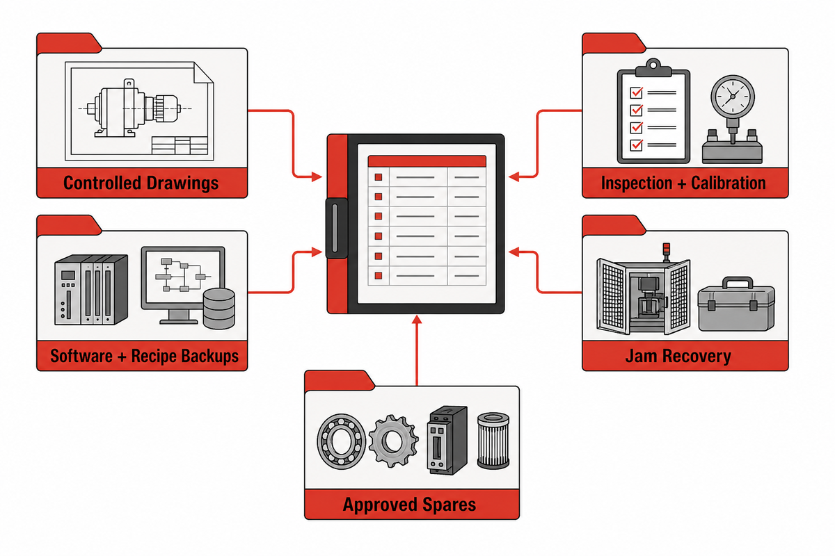
A technical handoff should provide the owner with the information necessary to replicate the accepted state and to identify and diagnose a departure from that state. The register should cover controlled drawings, tooling identifiers, software and recipe backups, inspection and calibration methods and limits, alarm thresholds, jam-recovery procedures, approved spares, data access and control, retention policies, and ownership of changes.
Maintenance isn’t only a schedule of lubricants and spare sensors. Clearing a jam, adjusting a feeder, changing tooling, or entering a guarded area can create hazardous-energy exposure. The applicable legal duties depend on the installation. In the United States, 29 CFR 1910.147 defines covered servicing activities and energy-control requirements, subject to its scope and exceptions. The site’s responsible safety team must determine and verify the actual procedure; a machine manual or control-circuit stop isn’t a global compliance decision.
For supplier context, ZEUEE’s company profile identifies Shenzhen Zeyu Intelligent Industrial Science Technology Co., Ltd., founded in 2005, with a 20,000 m² facility, ISO 9001:2015 certification, and delivery experience across more than 30 countries. While these company facts do not replace evidence of project acceptance, they help the buyer identify which company is responsible for the engineering handoff.
What Is Changing in Handle Assembly Automation?
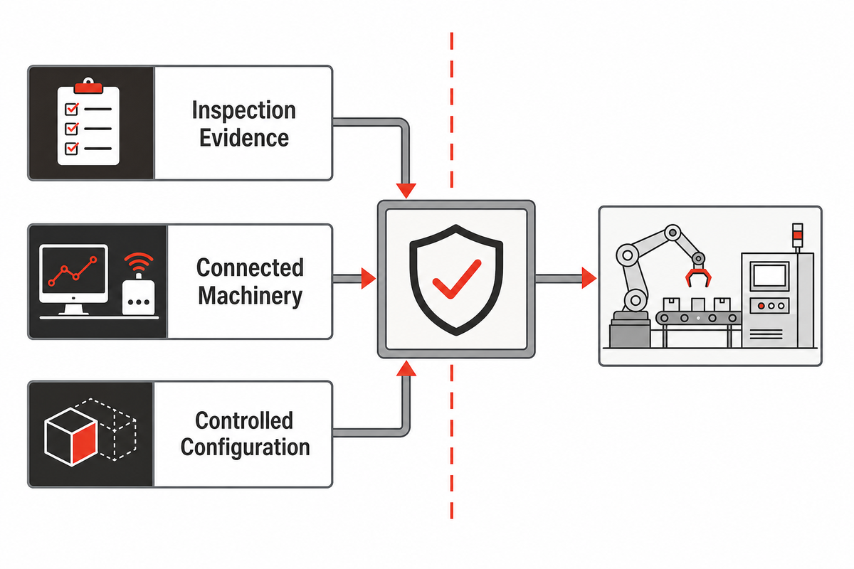
Three changes matter more than a generic market forecast. First, inspection is moving beyond simple presence checks toward alignment guidance, in-process decisions, and record capture. The gain is better evidence for defined tasks, not proof that vision replaces every gauge or functional test.
Second, connected machinery adds software, data, access, and cybersecurity questions to the acceptance boundary. The official ISO page says ISO 12100:2010 remains current after its 2022 review and flags a replacement draft. A 2025 technical update also connects revision work with connected machinery, AI, software, and cybersecurity. The European Commission’s machinery page confirms that Regulation (EU) 2023/1230 generally applies from January 20, 2027, with some provisions applying earlier. Freeze the applicable edition and market requirements in the project rather than writing “latest standard” without a date.
Third, product variety leads to controlled configuration and proof trials being of great value. A flexible presentation method can reduce dedicated change hardware for some families, but it does not remove the need to prove separation, pick access, recovery, surface protection, and released output for each approved variant.
When the Guide Should Hand Off to a Solution Review
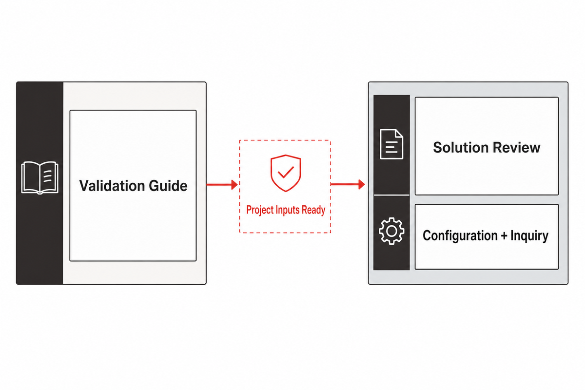
An informational handle assembly planning guide stops before model selection, station layout, utility consumption, delivery schedule, price, ROI, and quotation. Those decisions require the actual handle family, host product, joining method, inspection plan, throughput boundary, floor interface, and market requirements.
When those inputs are ready, review ZEUEE’s Handle Assembly Machine solution page. It owns the commercial configuration and project inquiry path, while this article remains the educational validation guide. For a wider application boundary, see custom automation equipment or the automated assembly line overview.
Handle Assembly Machine FAQ
What is the difference between a handle assembly machine and a handle making machine?
A handle making machine shapes or forms a handle, such as wire forming or molding a grip. A handle assembly machine joins components or attaches a completed handle to a host product. Sometimes production cells perform both of these tasks, but the names alone don’t prove this. Write the incoming parts and outgoing product, show the joining steps, checks, and exclude upstream and downstream operations that are outside the scope. This allows buyers to compare proposals for the same work.
Can one handle assembly machine run every handle type?
No universal design runs every handle. Range depends on the type of material, geometry, tooling, processing, inspection, and changeover. Define the approved family and prove representative variants. Prove the most difficult approved variants, their change parts, and the first-piece release rule before production.
Which part-feeding method is best for handle components?
There is no single best method. A production-representative proof trial should be used to decide the best means. Compare orientation yield, surface damage, pick success, recirculation, restart behavior, and recovery with production-representative parts before choosing a feeder for the application.
Why is qualified output lower than the nominal cycle rate?
Nominal cycle usually excludes some combination of stops, speed loss, replenishment, changeover, rejects, quarantine, and delayed release. The gap becomes a loss budget that separates availability, running-speed, and first-pass release effects. Qualified output counts only released good units inside an agreed time boundary.
What should a handle assembly machine FAT and SAT prove?
FAT and SAT should prove the agreed product and machine configuration under documented conditions, including traceable measurements, failures, recovery, containment, records, and good-output accounting. Use the same frozen product definition and decision rules at both stages. SAT also checks the installed site boundary.
What information should a manufacturer receive before machine design begins?
Provide controlled drawings and representative parts and describe the variant mix and variability. Describe packaging and storage conditions. Provide processing, joining, and inspection requirements; define the output clock, give reject conditions and reason for rejection, and describe changeover requirements. Give site conditions and interfaces, identify applicable standards, and describe handoff expectations.
References & Sources
WHY WE WRITE THIS
About ZEUEE Engineering Insights
ZEUEE shares technical guides based on real automation project experience. Since 2005, we have designed and manufactured non-standard automation equipment for connector assembly, wire harness production, robotic lines, vision inspection, and smart factory upgrades.
Founded in 2005
20,000 m² production base
120+ specialists
150+ R&D patents
ISO9001:2015 certified