Get in touch with Zeyu lntelligent Industrial Company

Robotic Production Line Architecture: Kinematics, Inter-Station Coupling, Buffers, and Zoned Safety

Updated October 2026
Placing four standalone robot cells next to each other won’t create a robotic production line. When robots are applied without a coordinated datum transfer, workcells can amplify micro-stops rather than multiply throughput. Using the right types of robot and buffer queues will help to ameliorate production errors. Modern manufacturing dictates that engineers treat manipulators, conveyors, feeders and safety zones as coupled systems.
A robotic production line integrates multiple robot workstations using automated workpiece transfer, deterministic fieldbus handshakes, and zoned safety interlocks. Engineers size buffers to isolate brief station stops. They also match 6-axis, SCARA, delta, and collaborative robots to station physics so net good-part output meets shift takt targets.
Quick Specs: Multi-Robot Line Engineering Baseline
| Integration Budget Scope | Budget for EOAT, feeding, transfer, vision, safety, controls, and commissioning alongside the robot arms |
| Pose Repeatability vs. Pallet Datum | Verify repeatability at the specified load and test conditions, then validate the complete pallet-to-tool tolerance chain |
| Equal-Station Illustration, Not a General OEE Rule | Budde illustrates 97.9 percent per station across 5 stations and 98.95 percent across 10; validate actual line OEE from measured availability, performance, and quality |
| Asynchronous Station Buffer | Size usable buffer capacity from recovery time and station cycle time; distinguish full pallets from empty positions |
| Governing Safety & Data Standards | ISO 10218-1:2025, ISO 10218-2:2025 (absorbing ISO/TS 15066), OSHA 29 CFR 1910.147 LOTO, and OPC 40010-1 |
- System coupling beats individual arm speed: Unnecessary PLC handshake delays or unbuffered feeder jams can reduce shift output despite faster robot wrist motion.
- Kinematics follow insertion physics: SCARA robots dominate press-fits and screwdriving. Six-axis arms handle compound-angle welding, dispensing and CNC machine tending.
- Buffers absorb jitter, not permanent bottlenecks: Pallet queues buffer brief recovery stops. A persistently slower station limits sustained output; assess process changes, task redistribution or parallel capacity.
- Commercial configuration path: This engineering guide provides the sizing and architectural math for systems that are vendor neutral. For turnkey configurations and pricing, see our Robotic Production Line engineering solutions page.
What Separates a Robotic Production Line from Standalone Robot Cells and Fixed Hard Tooling?
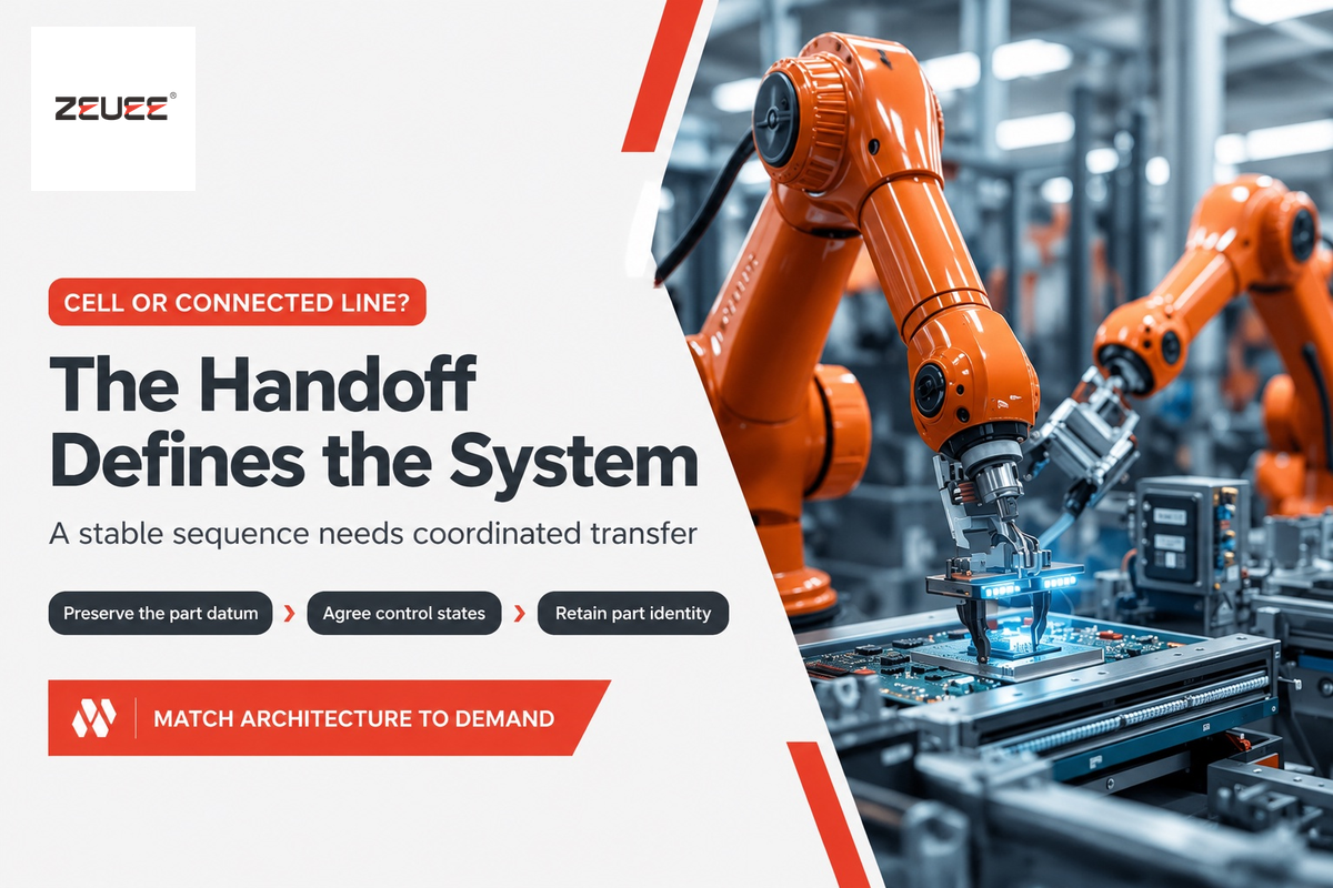
A robotic production line integrates multiple robot workstations into a single deterministic flow with datum-preserving part transfers, supervisory PLC handshakes, and zoned safety interlocks. Standalone robot cells may rely on batch carts to transport parts between cells. Hard tooling locks cam-driven mechanisms to a high-volume part, limiting the functionality of the cell.
In the global manufacturing industry, customers often mistake a row of isolated workcells for a true integrated line. For automotive assembly and aerospace plants choosing a first industrial robot, engineers should separate cell design from line architecture. A single assembly robot performs an assembly task such as spot welding a bracket or driving four fasteners. The robot then drops the finished part into a plastic tote. Human labor transports the tote to the next workstation, where it’s queued up with other work-in-process parts, risking scratches and lost serial traceability without suitable handling and tracking.
An integrated robotic assembly line replaces manual tote batching with a continuous conveyor or pallet transport backbone. When deploying robots in assembly, linked assembly robots take over repetitive assembly work and cut total production time. Combining speed and precision across connected stations paired with ai-driven vision helps revolutionize high-mix manufacturing. According to Fortune Business Insights’ assembly automation market report, global assembly automation reached USD 35.63 billion in 2025. The market is projected to grow from USD 38.01 billion in 2026 to USD 66.91 billion by 2034 at a 7.3% compound annual rate.
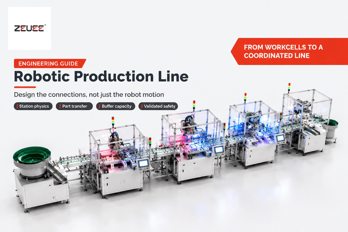
Hardware capital distribution is another surprise for first-time buyers. A turnkey budget includes the robots as well as end-of-arm tooling, carrier pallets, feeding, vision, safeguarding, controls and commissioning. ZEUEE’s published robotic line showcase illustrates integrated feeding, handling, servo pressing, displacement inspection and sorting. The press-cell example illustrates process integration; it isn’t a performance guarantee of a complete, multi-station line.
| Engineering Dimension | Standalone Robot Cells | Linked Robotic Production Line | Fixed Hard Tooling (Cam / Dial) |
|---|---|---|---|
| Typical Annual Volume | Variable batches and independent operations | Sustained demand with a stable sequence | Stable, repeated high-volume product geometry |
| Target Takt Time | Each cell follows its own operation cycle | Balance station cycles to required good-part output | Dedicated tooling optimized for a repeated cycle |
| SKU Variant Flexibility | Flexible fixtures; validate manual changeover time | Recipe selection plus validated tooling changeover | Dedicated tooling; major geometry changes need retooling |
| Inter-Station Part Transfer | Manual carts, totes, or batch trays | Asynchronous pallet conveyor or indexed transfer | Mechanical cam dial or rigid walking beam |
| Datum Preservation | Can be lost at a tote drop; re-fixtured at each cell | Preserved through validated carrier locating features | Hard mechanical nests locked to cam stroke |
| Fault Propagation Behavior | Partly isolated by floor inventory totes | Decoupled only while usable buffer capacity remains | Possible full line stop on a jam |
| Bare Manipulator Cost Share | Include tooling, guarding, programming, and validation | Include transfer, feeding, inspection, and line controls | Minimal share (cam actuators and slides dominate) |
| Serial Unit Traceability | Batch lot level unless unit identification is provided | Part-level tracking via pallet RFID and a project-defined traceability interface | Shift register pass/fail ejection; additional unit tracking can be specified |
| Capital Reuse at Next Generation | High reuse of robot arm and safety enclosure | High reuse of arms, conveyors, and safety PLCs | Low reuse of custom cam tooling when product geometry changes |
| Best Industry Fit | Job shops, low-volume welding, sub-assemblies | Automotive components, 3C electronics, medical devices | Single-SKU caps, syringes, high-speed connectors |
How do you decide between standalone robot cells and a linked robotic production line?
For independent scheduling or frequent tooling changes or uncertain upstream supply, use standalone cells. For a stable process and repeatable demand, use linked cells. Consider the cycle time of stations, changeover time, good-part output, and volume before deciding on the right architecture.
Our interactive Automation Maturity Stage Selector maps part volume, process consistency and process stability to the right architecture. Early linking of cells before stabilizing part tolerances can turn four independent cell stops into a single line stop.
Matching Robot Kinematics to Station Physics: 6-Axis Articulated, SCARA, Delta, and Cobots
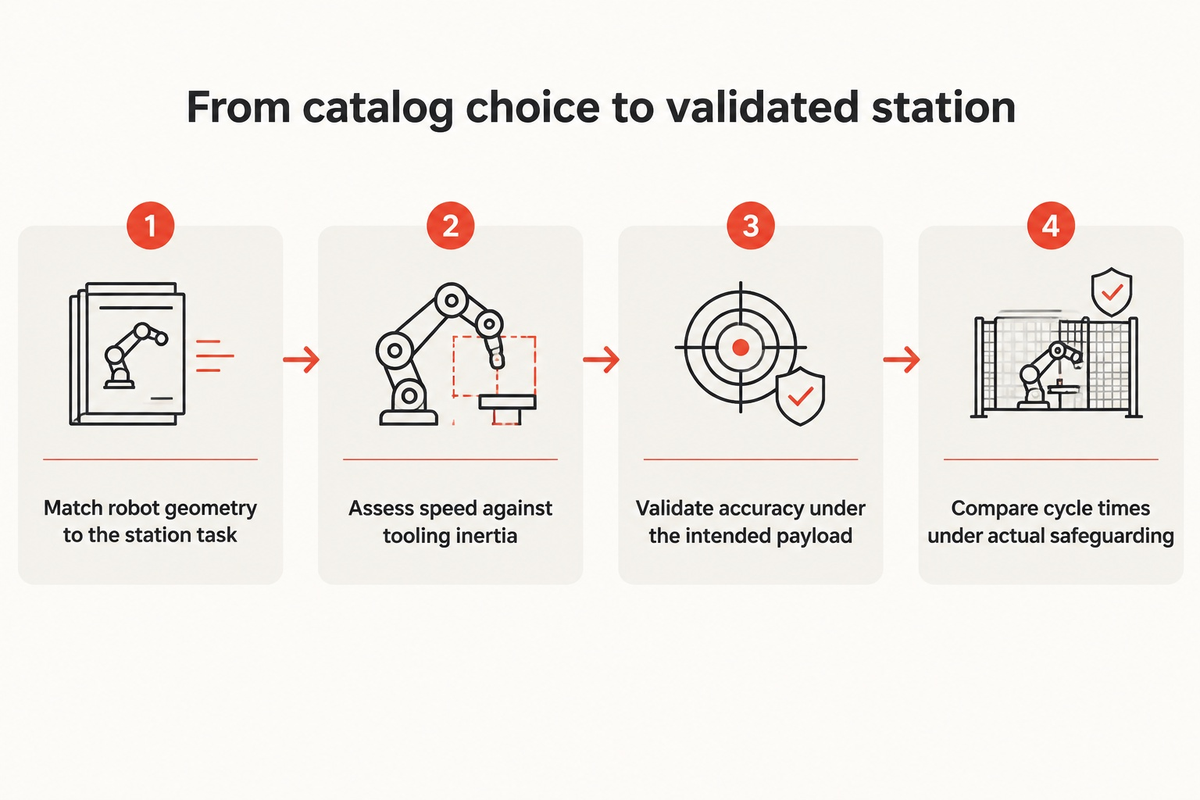
Assign SCARA robots to vertical Z-axis insertion and screwdriving. Use 6-axis articulated arms for compound-angle welding, dispensing, and machine tending; delta robots for high-speed conveyor picking; and collaborative robots for operator-shared stations. Engineers assess catalog speed against end-of-arm tooling inertia and validate loaded station accuracy, using locating pins or vision where appropriate.
According to the International Federation of Robotics World Robotics 2026 report, the global operational stock of industrial robots surged 9% to reach 5 million units in 2025. Annual global robot installations are forecast to hit 655,000 units in 2026 and reach 806,000 units by 2029. In modern robotics across this manufacturing landscape, high-performing lines rarely use a single robot geometry for every workstation. Instead, engineers evaluate the specific application of robots at each station to balance precision and speed.
| Robot Kinematic Type | Axes / DOF | Primary Station Assignment & Kinematic Limit |
|---|---|---|
| SCARA Robot | 4 axes (X-Y-Z-Theta) | Vertical PCB insertion, pin press-fit, screwdriving; cannot tilt tool axis sideways |
| Compact 6-Axis Articulated | 6 axes | Compound-angle housing assembly, 3D adhesive dispensing, connector mating |
| Medium 6-Axis Articulated | 6 axes | CNC machine tending, arc welding, deburring, multi-cavity injection unload |
| Heavy 6-Axis Articulated | 6 axes | Automotive body-in-white spot welding, battery pack handling, end-of-line palletizing |
| Delta Parallel Robot | 3 to 4 axes | High-speed conveyor tracking, food and beverage or blister sorting; validate speed for the selected payload and path |
| Collaborative Robot (PFL Mode) | 6 axes | Human-robot collaboration, manual pre-kitting, torque verification (speed requires application-specific risk assessment) |
| Hybrid Cobot with Area Scanner | 6 axes + SSM | Speed and Separation Monitoring adjusts operation according to validated separation distances |
| 7th-Axis Linear Track Robot | 6 + 1 linear axis | One articulated robotic arm tending parallel long-cycle test or machining enclosures; validate the number and travel times |
| AMR / Mobile Manipulator | Mobile base + 6 axes | Decoupled feeder replenishment, kitting tray delivery, and quarantine bin swapping |
A frequent engineering mistake is treating a robot’s catalog repeatability as its real-world assembly clearance. Under ISO 9283:1998 performance test criteria and RoboDK’s ISO 9283 validation documentation, pose repeatability is measured at just 5 configurations across 30 cycles; the 75 mm/s figure in RoboDK is one example test speed. Catalog repeatability is model-specific and is not the same as absolute positioning accuracy. RoboDK explains why broader configuration coverage is useful when evaluating accuracy. Validate the selected robot under the intended payload and operating conditions. When a multi-station line passes a carrier pallet from Robot 1 to Robot 4, thermal drift and pallet stop clearance stack up. Each precision station needs validated locating accuracy; mechanical locating shot-pins or 2D vision offset correction are possible methods.
Can collaborative robots match industrial robot cycle times on a multi-station line?
Collaborative robots can match some station cycles, but the comparison must use the validated application, payload, tooling, and human-access conditions. There’s no universal 250 mm/s operating limit for every power-and-force-limited application. Compare cycle times under the actual safeguarding arrangement. Speed and separation monitoring may permit faster motion when people remain outside the validated protective separation distance.
In cobot assembly applications, assess a single cobot for end-of-line inspection, label application, or low-rate sub-assembly against the required cycle time and application risk assessment. A traditional robot may work behind a fixed perimeter; robots like hybrid cobots may pair laser scanners with force limiting. For manufacturers who want to stay competitive on faster production runs, assess SCARA or compact 6-axis handling robots for the core tasks under validated safeguarding.
The 5-Interface Cell-to-Line Coupling Matrix: Where Multi-Robot Integration Succeeds or Fails
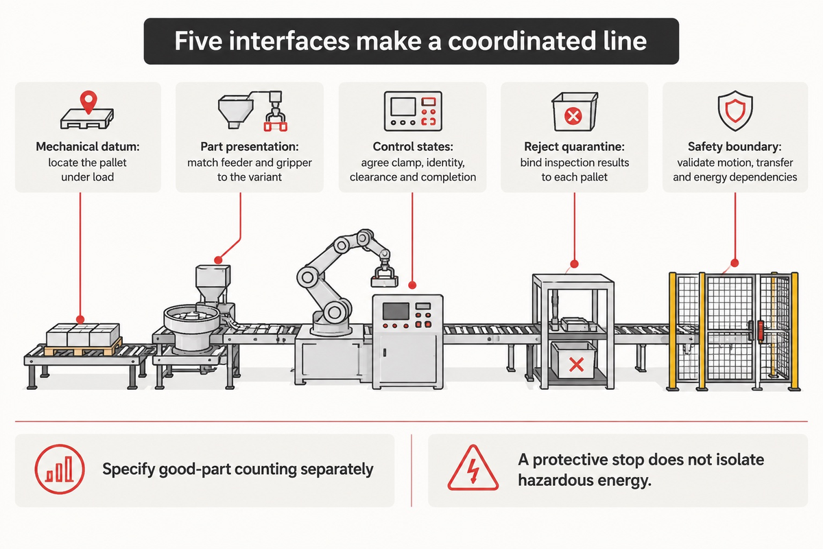
Multi-robot integration production lines succeed or fail across five inter-station interfaces: mechanical datum nests, upstream part presentation to EOAT, deterministic fieldbus state machines, RFID-linked inline quarantine gates, and zoned safety interlocks. Auditing these five interfaces before finalizing layout CAD models helps expose handoff, calibration, and control mismatches before commissioning.
5-Interface Cell-to-Line Coupling Matrix
- At Interface 1 (Mechanical Datum and Workpiece Handoff), lateral guide play is introduced on the carrier pallets riding on a conveyor belt. Before a SCARA robot or 6-axis arm performs high precision insertion, a pneumatic lift-and-locate unit raises the pallet off the belt. Engagement of hardened conic shot-pins to diamond and round bushings establishes station registration; verify its repeatability against the assembly tolerance under operating load.
- Assembly line robots lose cycle time at Interface 2 (Upstream Part Presentation and EOAT Coupling) if they are required to pick bulk, tangled components from a random bin. Single-SKU high-speed runs are paired with vibratory bowl feeders. A servo gripper, along with a camera-guided flexible feeding system, is used for a multi-SKU family.
- Via Interface 3 (Deterministic PLC & Fieldbus State Machine), each line robot controller exchanges real time interlock bits (Pallet_Clamped, Part_Type_ID, Clear_Of_Fixture, Cycle_Done_Pass) with the supervisory line PLC over PROFINET or EtherNet/IP. Integration issues with the supplier control and calibration systems are addressed in the supplier commentary in IndustryX’s robotic system integration commentary. In the project data specification, separately classify gross machine cycles and verified good parts. The OPC 40010-1 robotics information model addresses asset management and condition monitoring. It does not define the project good part counting logic.
- Within Interface 4 (Inline Vision & Reject Quarantine Gate), the control system associates machine vision and servo press force-displacement results with each carrier pallet’s identifier. In the event of a sub-assembly failure at Station 3, downstream stations read the reject flag and pass the pallet untouched to a locked quarantine chute. This gate is intended to block defective sub-assemblies from passing along and potentially damaging downstream tooling or other good part sub-assemblies.
- With Interface 5 (Inter-zone Safety & Interlock Boundary), networked safety PLCs using PROFIsafe or CIP Safety logically subdivide the line into buffered zones protected by controlled light-curtain muting at pallet transfer tunnels. Untouched zones may continue production only if a validated risk assessment demonstrates that the motion, transfers and energy of the zone will not endanger a person in the stopped zone. Protective stops do not in and of themselves isolate hazardous energy.
Synchronous Indexed vs Asynchronous Pallet-Buffered Topologies (With Finite-Buffer Sizing Math)
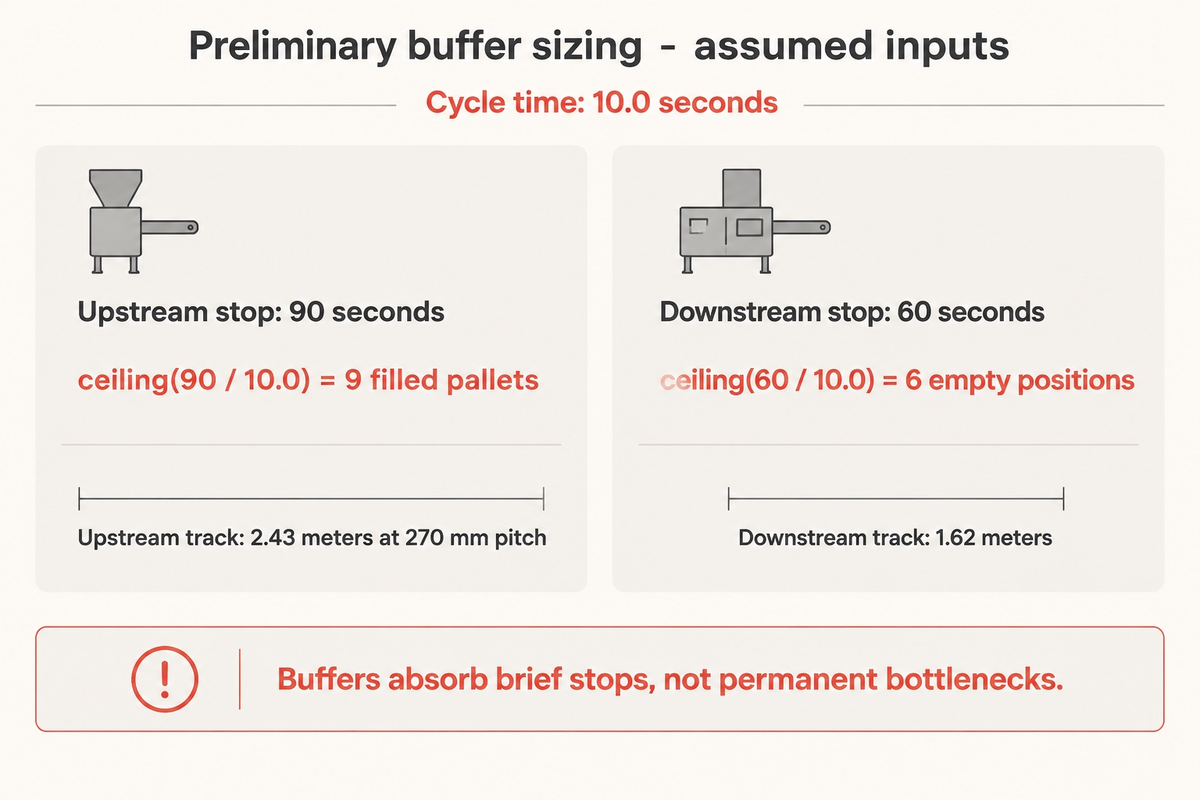
Choose a synchronous indexed system when station cycle times are short and uniform and dedicated to a single low-mix product. Use an asynchronous pallet conveying system with limited buffers to accommodate cycle-time variability and feeder micro-stops, with buffer capacity sized to limit downstream robot starvation.
As Assembly Magazine’s pallet-handling conveyor engineering analysis explains, a synchronous conveyor advances every carrier simultaneously. With a synchronous system, if a station is down because of a sensor fault, all pallets on the line come to a stop. An asynchronous pallet transfer system uses low friction conveyance to transfer carriers. Pallets accumulate smoothly before and after workstations.
In Bill Budde’s automated assembly throughput analysis in Assembly Magazine, standard asynchronous lines buffer 2 pallets per workstation. High-speed lines buffer up to 5 or 6 pallets per station so fast robots keep running while a neighbor clears a minor fault. For a broader look at non-robotic transfer timing, see our automated production line flow and buffering guide.
Why can’t inter-station buffers fix a permanent station cycle-time bottleneck?
Inter-station pallet buffers absorb only momentary rate mismatches due to cycle time jitter and micro-stop recovery events. With respect to the robotic assembly system, if Station 4 requires 20 seconds per part while Stations 1-3 run at 10 seconds, all finite upstream buffers quickly fill to capacity. That full queue blocks upstream robots until Station 4 releases space; sustained output remains limited by its effective capacity.
To manage the assumed 20 second bottleneck (due to UV adhesive cure, helium leak test, or complex assembly check, etc.) engineers split the slow operation across two parallel stations (m = 2). Parallel operations yield an effective station discharge interval of 20 seconds/2 = 10 seconds.
Worked Engineering Calculation #1: Preliminary Finite Pallet Buffer Sizing
Design Scenario (Assumed Inputs): A 6-station robotic assembly system runs at a bottleneck station cycle time of T_cycle = 10.0 seconds (gross flow rate = 6.0 parts/minute). Upstream Station 1 uses a Bowl Feeder that experiences brief component replenishment micro-stops lasting up to T_recover_up = 90 seconds. Downstream Station 6 (inline vision and tray packing) takes T_recover_down = 60 seconds for blister tray magazine swaps.
- For Step 1 (Upstream Starvation Protection Buffer N_starve) , keeping the 10-second bottleneck robot working continuously during a 90-second upstream feeder stop requires N_starve = ceiling(90 s / 10.0 s) = 9 filled carrier pallets. This gives N_starve = ceiling (90 s / 10.0 s) = 9 filled carrier pallets.
- For Step 2 (Downstream Blocking Protection Buffer N_block) , preventing the bottleneck robot from being blocked during a 60-second downstream tray swap requires N_block = ceiling(60 s / 10.0 s) = 6 empty pallet positions. This gives N_block = ceiling (60 s / 10.0 s) = 6 empty pallet positions.
- For Step 3 (Physical Conveyor Queue Allocation) , using 270 mm pallet pitch across 9 upstream pallets requires 9 × 0.27 m = 2.43 meters of accumulation track. The 6-pallet downstream queue requires 6 × 0.27 m = 1.62 meters of track.
Calculating Net Good-Part Output: Why Robot Motion Speed Does Not Equal Line Throughput
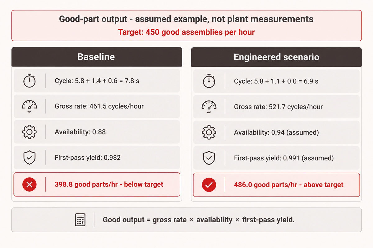
True station cycle time is the sum of robot motion time, index and clamp handshake time, and non-overlapped vision check time. Net good-part output per hour equals the bottleneck rate multiplied by line availability and first-pass yield when the running cycle already includes performance losses; otherwise include a separate performance factor. Path rounding and overlapping handshakes have a great effect on real throughput of a system.
When evaluating robotic systems, some buyers divide 3,600 seconds by the 5.8 second motion of the robot and expect a line to produce 620 parts per hour. In reality, serial coupling reduces the line’s availability when stations lack sufficient decoupling buffers.
Bill Budde illustrates how adding coupled stations raises the individual performance needed to meet an overall target. His equal-station example should not be treated as a universal formula for buffered lines. Measure line availability, performance, and quality on a consistent time and output basis.
At the station level, robot programming choices produce similarly strange cycle time results. Many programmers assume a straight linear path (MOVL) between pick and place points is fastest because a straight line is the shortest distance.
Stephen Bolin explains that the shortest geometric path need not give the shortest cycle time. Joint motion and blending through noncritical intermediate points can reduce unnecessary deceleration, subject to collision checks and process constraints.
Programmers can assess noncritical air-cut linear moves for joint moves (MOVJ) and zone blending (CNT on FANUC, ZoneData on ABB; check the specific settings on KUKA robots), plus feedback from gripper reed-switch signals instead of fixed PLC timers. Measure the cycle time and validate collision clearance, equipment limits, and process quality before accepting either change.
Worked Engineering Calculation #2: 60-Minute Net Good-Part Throughput Envelope Audit
Audit Scenario (Assumed Inputs): An automotive supplier needs 450 good assemblies per hour (demand takt = 8.0 s/part) from a 6-station robotic production line building automotive components. At the slowest station (station 3 – screwdriving), robot arm motion takes 5.8 s, a pallet lift-and-clamp takes 1.4 s, and post-drive vision checking takes 0.6 s.
| Throughput Envelope Stage | Formula / Parameter | Baseline Unoptimized Line | Engineered Buffered Line |
|---|---|---|---|
| 1. Gross Bottleneck Cycle (c_max) | t_motion + t_clamp + t_vision | 5.8 + 1.4 + 0.6 = 7.8 s | 5.8 + 1.1 + 0.0 (overlapped) = 6.9 s |
| 2. Gross Theoretical Rate | 3,600 s / c_max | 461.5 gross cycles/hour | 521.7 gross cycles/hour |
| 3. Coupled Line Availability (A_line) | Running minutes / 60 min | 0.88 (52.8 min; unbuffered jams) | 0.94 (56.4 min; 6-pallet buffers; assumed, not measured) |
| 4. Cumulative 6-Station FPY | (y_station)^6 | 0.982 (0.997 station yield) | 0.991 (telecentric vision + pins; assumed, not measured) |
| 5. Net Deliverable Good Output | Gross × A_line × FPY | 398.8 good parts/hr (FAILS 450) | 486.0 good parts/hr (EXCEEDS 450) |
Engineering Takeaway: In this assumed example, though the 5.8 s robot motion beat the 8.0 s takt target, non-overlapped handshakes and unbuffered micro-stops resulted in a shortfall of about 51 parts/hour. In this assumed example, overlapping vision inspection during pallet transfer and adding 6-pallet buffers accompanies assumed availability and yield gains, raising net deliverable output by 87.2 good parts/hour to 486 good parts/hour. You can design your own station parameters in ZEUEE’s interactive Throughput and Cycle Time Estimator.
Zoned Safety Architecture (ISO 10218-2:2025) and Hazardous Energy Isolation (LOTO) for High Uptime
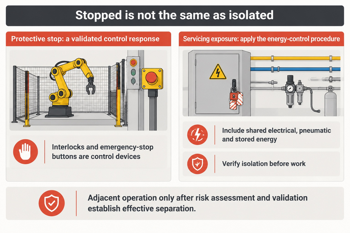
Validated safety zones may contain a stop without stopping every workcell. Zones that are unaffected by the stop may continue if their motion, transferred material and energy can’t endanger the personnel in the stopped zone. As per OSHA 29 CFR 1910.147, servicing with hazardous unexpected energization or stored-energy exposure requires the applicable energy control procedure.
In February 2025, the International Organization for Standardization published ISO 10218-2:2025 for industrial robot applications and robot cells (223 pages) alongside ISO 10218-1:2025, replacing the 2011 editions. Detailed reviews appear in the American National Standards Institute (ANSI) ISO 10218-1:2025 technical brief and NEXCOM’s ISO 10218:2025 compliance guide. The 2025 revision introduces Class I and Class II robot classifications for functional-safety requirements and incorporates collaborative requirements formerly in ISO/TS 15066 into the core standard. It also adds cybersecurity requirements insofar as cybersecurity affects industrial robot safety.
Normally, guard-door openings are protected by the designed protective-stop function; an emergency stop serves a different purpose. Select and validate the stop response as part of the application risk assessment. Zones must address reaching and moving work pieces, shared actuators, and stored energy, not just fence locations. A buffer supports production only after these safety dependencies are satisfied.
Does an interlocked safety gate stop satisfy lockout/tagout (LOTO) on a robotic line?
No. Safety interlocks and emergency-stop buttons are control devices, not energy-isolating devices. Servicing that exposes workers to hazardous, unexpected motion or stored energy requires the applicable energy-control procedure. OSHA’s minor-servicing exception is narrow. The minor-servicing task must occur during normal production operations and be routine, repetitive, and integral to using the equipment for production. Other means must provide effective protection.
Define isolation boundaries for the actual servicing task, including shared electrical, pneumatic, gravitational, and other stored energy. Adjacent zones may be operational after the risk assessment and validation indicate effective separation. Follow the documented energy-control procedure and verify isolation before work is performed. A stopped robot alone isn’t evidence of an isolated machine.
Cross-Station Failure Propagation Diagnostic: Preventing Cascading Line Stops
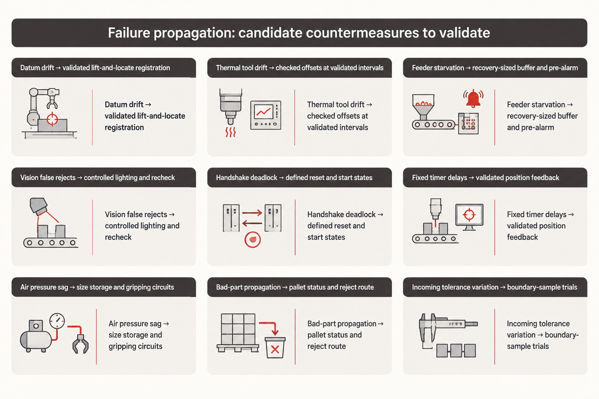
There are a number of ways that faults can be propagated at robotic stations. Use the diagnostic below to identify faults, their symptoms, and a possible cause.
Bill Budde, in Assembly Magazine’s automated assembly article mentions that more than 50% of production stoppages happen because tools at workstations aren’t forgiving enough for part dimensional variation. Also in IndustryX’s field integration analysis, TCP calibration errors, if not checked, can ruin a production batch. In developing smart manufacturing cells, AI and robotics teams considering machine learning algorithms on vision and torque streams for predictive maintenance should validate drift alerts against actual station measurements before relying on them.
Cross-Station Failure Propagation Diagnostic
It illustrates possible failure propagation across stations and candidate hardware or control countermeasures for validation.
| Failure Mode | Originating Station | Downstream Cascade Mechanism | Telemetry / PLC Symptom | Engineering Countermeasure |
|---|---|---|---|---|
| 1. Cumulative Datum Drift | Conveyor pallet stop | Unclamped belt guide play causes Station 4 SCARA pin press-fit to jam | Z-axis servo torque limit alarm at Station 4 | Lift-and-locate conic shot-pins with project-validated locating repeatability |
| 2. Thermal TCP Drift | Welding / dispensing arm | Warm-up expansion shifts weld bead or glue path, failing Station 6 test | First-hour yield normal, then progressive offset during a run (illustrative) | Automated laser TCP bullseye check with offset write at validated intervals |
| 3. Feeder Starvation Cascade | Station 1 vibratory bowl | A track jam can starve downstream stations once their available work is consumed | Stations 2 to 6 report Starved_Wait across shift logs | Size the decoupling buffer for recovery time and cycle time; add a low-level track pre-alarm |
| 4. Vision False-Reject Purge Loop | Inline 2D camera station | Ambient glare on shiny housings triggers false rejects, starving pack | High machine cycle count but low released GoodQuantity | Telecentric coaxial lighting + shrouded enclosure + re-verify chute |
| 5. PLC Handshake Deadlock | Inter-station transfer gate | Post-reset Robot A waits for Pallet_Ready while PLC waits for Arm_Home | Zero fault lamps active, but line sits frozen in Run mode | Deterministic PackML Resetting to Idle to Starting to Execute state machine |
| 6. Fixed-Timer Handshake Delays | EOAT gripper valve | Illustrative assumption of serial, non-overlapped waits: fixed 300 ms PLC timers on 4 handshakes add 1.2 s dead time per cycle | Line misses shift takt target despite zero downtime faults | Direct cylinder position feedback with validated I/O timing |
| 7. Manifold Air Pressure Sag | Shared pneumatic header | Simultaneous vacuum ejectors cause manifold pressure drop, dropping parts | Random intermittent vacuum loss alarms across Stations 2 and 5 | Size local air storage and gripping circuits from measured demand and the safety assessment |
| 8. Unquarantined Bad-Part Pass | Station 2 press-fit | Cocked pin enters Station 3 laser weld, crashing nozzle and fixture | Collision detection trip on downstream robot wrist | RFID pallet status bit lock + physical reject spur before Station 3 |
| 9. Part Tolerance Intolerance | Supplier incoming batch | Molded flash on incoming parts can jam a rigid feeder escapement | Repeated short stops eroding shift output | Run upper/lower boundary samples during FAT + compliant EOAT jaws |
Pre-RFQ Engineering Readiness Checklist: What to Freeze Before Requesting a Line Quote
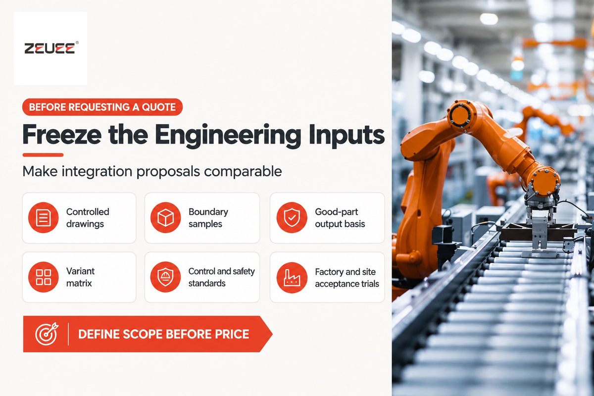
Before requesting a custom robotic production line quote, buyers should freeze 3D STEP and 2D GD&T drawings, physical boundary samples, net good-part takt targets, a 3-year SKU variant matrix, plant PLC and safety standards, and two-stage FAT/SAT wet-run acceptance criteria. Complete input packages can reduce integrator contingency padding and the time required for commissioning.
When a manufacturer sends a “10-part-per-minute robotic assembly system” request to an automation supplier, an integrator has to pad its initial cost estimate with significant risk contingencies, and that covers all the unknowns, from feeding to tolerancing to software. Freezing six engineering deliverables prior to issuance of a User Requirements Specification (URS) turns vague quotes into fixed-scope and comparable proposals.
- Provide controlled 3D STEP and 2D GD&T drawings to identify acceptable gripping surfaces, cosmetic no-touch zones, tolerances for press fits and datum locating features for every sub-component.
- Prepare Physical Boundary Samples at nominal dimensions, upper and lower tolerance limits, and known defective states. Integrators use these boundary sets to validate feeder tracks and machine vision thresholds during Factory Acceptance Testing (FAT).
- Describe your Net Good-Part Takt & Shift Basis by indicating the accepted units per hour, scheduled shift duration, planned changeover frequency, and the OEE denominator.
- Create a SKU Variant Matrix that differentiates software changeover from physical changeover. Set changeover acceptance times for each variant family and validate them during trials.
- Specify Plant Control & Safety Standards including mandatory PLC platforms (Siemens TIA Portal, Allen-Bradley Studio 5000, or Omron) and fieldbus protocols (PROFINET, EtherNet/IP, EtherCAT). Specify OPC UA information models and plant data interfaces separately. Include plant rules for ISO 10218-2:2025 and OSHA 29 CFR 1910.147 LOTO zoning.
- A Two-Stage FAT & SAT Run-Off Protocol is required. A production trial of an agreed duration must be performed at the integrator’s plant (FAT) demonstrating target first-pass yield and net throughput before crating. An identical trial must be performed after site installation (SAT).
For factory and site acceptance processes, familiarize yourself with our turnkey automation Systems Delivery Guide. After you’ve finalized your engineering package, use our Line ROI and Payback Calculator to model potential payback periods. Compare different system configurations on our Custom robotic production line page.
Frequently Asked Questions
How many stations justify linking standalone robot cells into an integrated robotic production line?
Join cells when a stable part family and repeated process sequence make automated transfer worthwhile. Perform a case study using required good-part output and handling costs.
Connecting successive operations can reduce tote loading labor across shifts. When component feeding, precision press-fit, laser welding, dispenses, and inline vision run on isolated island cells, manual carts create large work-in-process queues and handling damage. An asynchronous pallet conveyor can preserve a defined part datum through validated lift-and-locate nests.
What is the typical ratio between bare robot arm cost and total robotic production line investment?
Bare robot manipulators are only one part of turnkey robotic production line capital expenditure; obtain a project-specific cost breakdown.
The remaining project scope includes custom end-of-arm tooling, precision carrier pallets, lift-and-locate shot-pin units, flexible feeders, vision systems, 2D/3D machine vision, safety PLCs with light curtains, and integration of supervisory PLC and MES software, as well as Factory Acceptance Testing. It’s a common mistake in industrial capital planning to budget only for the bare robotic arms.
How do engineers handle product variant changeovers on a multi-robot assembly line without hours of downtime?
Universal carrier pallets, combined with servo grippers, automatic tool changers and recipe-driven vision programs, reduce the amount of manual work required to effect changes.
Different assembly variants are seated in multi-SKU lines, and identified by an RFID tag embedded in the pallet. For compatible variants, operators may avoid unbolting mechanical guide rails or re-teaching intelligent robots by hand. A new carrier pallet, upon arrival to a workstation, is identified by the PLC which automatically selects the robot program, gripper settings and camera recipes for that variant. Tooling changes must be measured independently from recipe selections.
Which industrial communication protocols coordinate multi-robot production lines?
Real-time station handshakes use PROFINET/PROFIsafe, EtherNet/IP with CIP Safety, or EtherCAT, with OPC UA providing communication to higher-level systems.
Deterministic fieldbuses handle robot-to-PLC clamp signals; validate their timing in the selected configuration. OPC 40010-1 is used to retrieve asset and condition data of robot equipment. Good-part counters and their plant MES mapping must be specified separately.
Why does a robotic production line miss its target OEE even when every robot hits its catalog cycle time?
Ignoring inter-station handshakes and serial availability decay overstates the output of coupled systems.
A robot-only motion simulation may omit pallet index time, lift and locate clamping, PLC handshake delays, and non-overlapped vision checks. Coupled stops reduce line availability. Do not interchange station availability with station OEE or multiply station OEE values as a general rule. Line availability, performance, and first pass quality should be measured for the same window of time. Inspection during transfer should be overlapped and filled pallet buffers should be sized to feeder recovery time. At a 10 second cycle time, 6 pallets cover 60 seconds, while 90 seconds requires 9 pallets.
What is the difference between FAT and SAT for a custom robotic production line?
FAT validates full-speed wet-run throughput and safety on the integrator’s floor before shipment, while SAT verifies performance after plant installation.
During Factory Acceptance Testing, the agreed sample quantity (covering dimensional limits and known defects) is provided by the buyer. The acceptance trials assess throughput and quality as well as the safety functions. Site Acceptance Testing is to confirm sustained OEE on plant utilities.
How does inline vision inspection prevent defective parts from wasting downstream robot cycles?
The control system associates inline camera and force-sensor pass/fail results with each pallet’s RFID identifier. Failed pallets are skipped or diverted.
Allowing an unacceptable crooked pin or missing O ring from Station 2 to enter Station 3’s laser welder risks crashing tooling. Binding each 2D/3D vision check and press curve to the carrier pallet’s RFID tag stops that cascade. The supervisory PLC directs failed carriers to a locked quarantine spur or instructs downstream robots to pass unworked carriers.
Ready to Turn Your Part Drawings and Takt Target into a Multi-Robot Line Architecture?
Send us your 3D STEP files, annual volume, SKU variant matrix, target shift output, and available production floor layout. ZEUEE’s automation engineering team will evaluate station kinematics, pallet buffer sizing, and zoned ISO 10218-2:2025 safety layout for your production floor.
ZEUEE’s Manufacturing Perspective
Shenzhen Zeyu Intelligent Industrial Science Technology Co., Ltd (ZEUEE) engineers custom assembly systems and precision testing equipment. Our ZEUEE intelligent automation engineering profile describes a 20,000 m² production base in Taihe, Jiangxi, completed in 2020. The 120+ team spans R&D, engineering, and production. ZEUEE reports ISO 9001:2015 certification and National High-Tech Enterprise status. Send part drawings and acceptance targets so our team can assess the required integration scope.
References & Sources
- ISO 10218-2:2025 — Safety requirements for industrial robot applications and robot cells (February 2025).
- ANSI Technical Brief: ISO 10218-1:2025 Robots and Robotic Devices Safety Overview (2025).
- ISO 9283:1998 — Manipulating industrial robots performance criteria and test methods.
- RoboDK Documentation: ISO 9283 Performance Testing and Repeatability Validation.
- IFR World Robotics 2026 Report: Five Million Robots Operate in Factories Globally.
- Bill Budde, Assembly Magazine: Defining Throughput in Automated Assembly Systems.
- Kate Nadeau, Assembly Magazine: Optimizing Assembly with Pallet-Handling Conveyors.
- Stephen Bolin, Automate (A3): Reducing Cycle Time in Robotic Material Handling Applications.
- IndustryX Analysis: 7 Robotic System Integration Mistakes and How to Avoid Them.
- NEXCOM Technical Guide: ISO 10218 Industrial Robot Safety Standard 2025 Revision.
- Fortune Business Insights: Assembly Automation Market Size & Growth Report (2025–2034).
WHY WE WRITE THIS
About ZEUEE Engineering Insights
ZEUEE shares technical guides based on real automation project experience. Since 2005, we have designed and manufactured non-standard automation equipment for connector assembly, wire harness production, robotic lines, vision inspection, and smart factory upgrades.
Founded in 2005
20,000 m² production base
120+ specialists
150+ R&D patents
ISO9001:2015 certified