Get in touch with Zeyu lntelligent Industrial Company

MIL-DTL-26482 Connector Machine: The Complete Connector Selection Guide

Updated July 2026
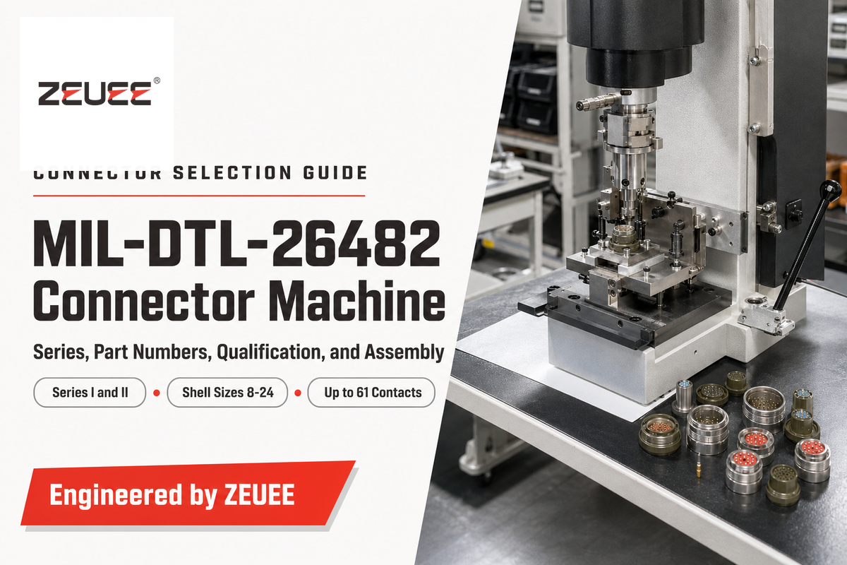
A MIL-DTL-26482 connector machine is the crimping, mating-force, or cable-assembly production equipment used to build connectors to the MIL-DTL-26482 specification – it is not the connector part itself. MIL-DTL-26482 is the U.S. military detail specification that covers a family of circular, bayonet-coupled electrical connectors designed for rapid mate/de-mate service in high-reliability aerospace, defense, and other applications. The specification and the machine are sometimes confused because “MIL-DTL-26482 connector machine” is a common search term used by assembly equipment seekers. It’s useful to keep the two concepts distinct. From the specification down to the machine that implements it, this guide separates the two, spec by spec.
The standard traces back to the 1950s as a derivative of the older MIL-C-5015 threaded-coupling family, originally built around 18-20 AWG contact sizes, and it now exists in two active series (Series I and Series II) with a shell size range of 8 to 24 and up to 61 contacts depending on shell size and insert arrangement. Known MIL-DTL-26482-qualified manufacturers include Amphenol Aerospace, ITT Cannon, Souriau, Cinch, TE Connectivity, and PEI-Genesis, among others. All build against the same base specification and insert-arrangement library. That market context matters when sourcing because a compliant part from one qualified manufacturer is generally interchangeable with another’s within the same shell size and arrangement code, whether purchased directly from the manufacturer or through a value-added distributor.
Quick Specs
| Shell size range | 8 to 24 |
| Max contact capacity | Up to 61 contacts (shell/arrangement dependent) |
| Coupling type | 3-point bayonet (quarter-turn lock) |
| Operating temperature | -55°C to +125°C (Series I) / -65°C to +200°C (Series II) |
| Mating cycles | 500 minimum |
| Contact plating classes | L (electroless nickel) / A (black anodized) / G (passivated stainless) / W (olive drab cadmium) |
| Governing document | MIL-DTL-26482 Revision J with Amendment 2 (dated 2024-03-05), Defense Logistics Agency |
What Is a MIL-DTL-26482 Connector?
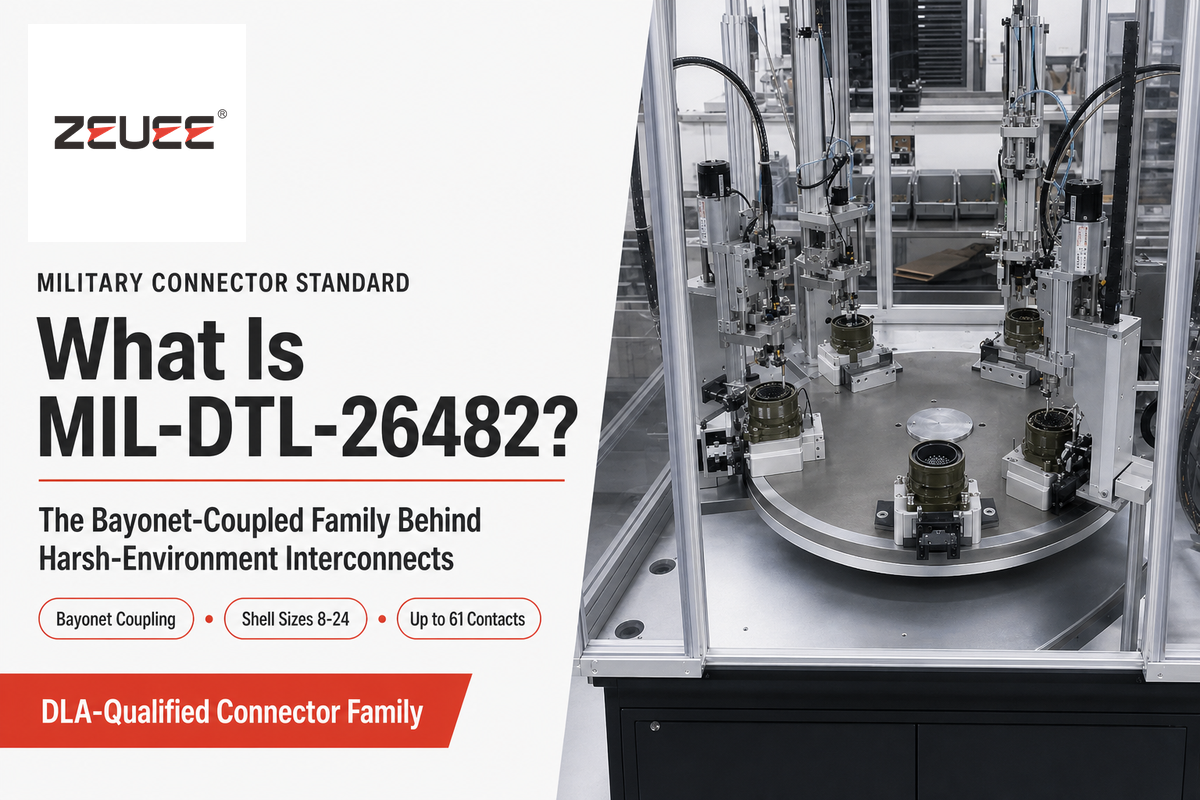
A MIL-DTL-26482 connector is a circular, bayonet-coupled electrical connector built to a U.S. military detail specification maintained by the Defense Logistics Agency. This military specification covers a receptacle half (typically the fixed, panel- or bulkhead-mounted side) and a plug half (typically the cable-mounted, mating side), with shell sizes 8 through 24 and up to 61 contacts depending on the insert arrangement selected.
Both halves lock together with a quarter-turn of a spring-loaded 3-point bayonet mechanism rather than a threaded coupling nut, which is the defining mechanical trait that separates this family from MIL-DTL-5015 and other threaded circular connectors covering the same general application space. Distributor catalogs frequently list the family plainly as circular with quick disconnect connectors — a circular mil-spec series of connectors and general-purpose interconnect hardware built around that same cylindrical quarter-turn-lock principle.
Available shell body plating finishes are Class A (anodize black), Class W (cadmium olive drab, older specification drawing finish), Class L (nickel, electroless), and Class G (stainless steel, passivated), giving engineers the flexibility to meet corrosion and performance requirements for specific applications. Contacts used in MIL-DTL-26482 connectors conform to SAE AS39029, a general-purpose contact standard used across other mil-spec circular connectors.
📐 Engineering Note
The fact that a machine tool or automated assembly machine can accommodate MIL-DTL-26482 shell sizes and contact types does not make every connector produced on that equipment a MIL-DTL-26482-qualified part. A machine’s ability to assemble the connector is separate from the connector manufacturer’s qualification to the specification.
Maintained by the Defense Logistics Agency, the MIL-DTL-26482 detail specification sits within the Department of Defense’s Modular Open Systems Approach (MOSA) push toward standardized, cross-program-interchangeable hardware rather than platform-locked one-off designs.
Bayonet Coupling and the MIL-DTL-26482 Shell/Contact System
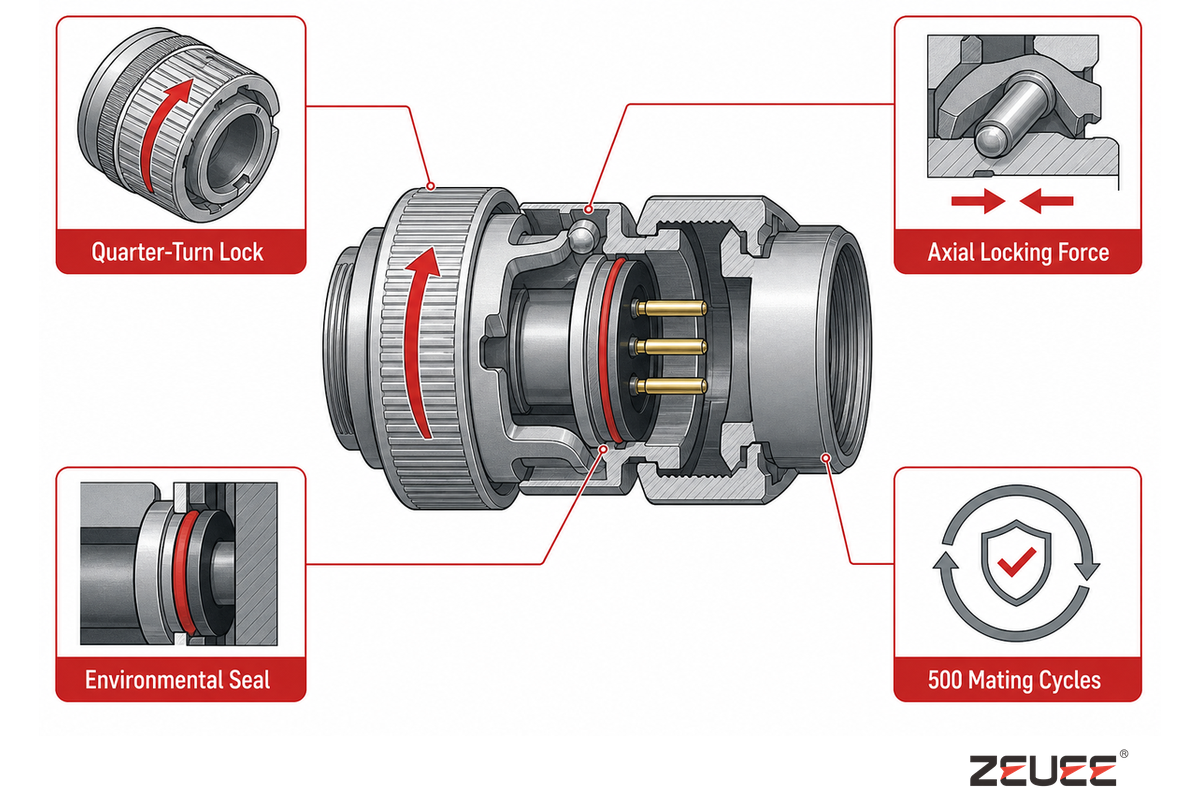
The bayonet mechanism on a MIL-DTL-26482 connector uses a spring-loaded pin or plunger riding in a cam-track cut into the mating shell, so that a quarter-turn of the coupling ring converts rotational motion into an axial locking force that pulls the two halves fully home and resists back-off under vibration. That self-locking, spring-restrained design, documented across several bayonet-connector patents spanning decades of incremental refinement, is why bayonet coupling was chosen over a simple threaded nut for applications where fast, tool-free mate/de-mate matters as much as vibration resistance: a bayonet connector locks and unlocks in a fraction of a turn, where a threaded coupling nut needs several full rotations to fully seat or release.
When a connector is properly assembled, it’s considered “environmentally sealed” at the Mating Face because the engagement mechanism pulls the connector halves together so tightly that an elastomeric seal is energized, preventing moisture and debris from contaminating the contact cavity. That feature, combined with the tight mechanical connection, is in large part why connectors, as a family, are specified for outdoor applications in ground vehicle and airframe wiring as well as benign indoor use.
What Contact Plating Options Does MIL-DTL-26482 Support?
Four plating classes are available for MIL-DTL-26482 connectors: L (electroless nickel), A (black anodized), G (passivated stainless steel), and W (olive drab cadmium). Class L is the general-purpose choice today. The right finish depends on the operating environment’s corrosiveness, conductivity, and EMI requirements rather than appearance, and finishes are not freely interchangeable without revising the governing assembly drawing.
A MIL-SPEC connector with a Class W (cadmium plated) finish, for instance, can’t be blindly replaced by one of a newer design or different finish type without the relevant assembly drawing being revised to reflect the change. Within an insert arrangement on a connector, both power and signal conductors can be populated in side-by-side contact positions, each contact size having its own associated plug tool and socket tool, which must be used to prevent damage to contact retention members.
Mating Cycles and Contact Reliability
MIL-DTL-26482 connectors are qualified to a minimum of 500 mating cycles under the base specification’s endurance testing. Contact-reliability degradation across repeated mate/de-mate cycles is driven primarily by contact-spring fatigue and plating wear at the mating interface, which is why bench-test and rework cycles outside final installation are worth running on sacrificial connector savers rather than burning down the mating-cycle budget of the production part itself. Reliable mating over the connector’s full service life depends on staying inside that rated cycle count, not just on a clean crimp at initial assembly. One of the foundational self-locking bayonet-coupling designs behind this mechanism is documented in US Patent 6,226,068 B1, part of the patent lineage referenced above.
Series I vs Series II: Which MIL-DTL-26482 Connector Should You Specify?
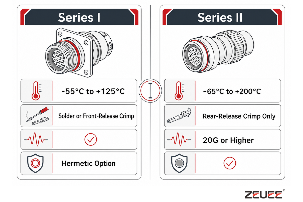
Series I and Series II are the two active MIL-DTL-26482 sub-families (also written MIL-DTL-26482 Series 1 and Series 2 in some drawings and distributor catalogs). They differ on coupling-release mechanism, backshell compatibility, hermetic sealing availability, and operating temperature range: Series I is rated -55°C to +125°C, while Series II is rated to a wider -65°C to +200°C.
A widely repeated figure claims Series I reaches -65°C to +175°C – that bracket recirculates across some secondary sources and even a large competitor guide, but it doesn’t match the manufacturer’s own published Series I data. Checking the primary source confirms the manufacturer’s own -55°C to +125°C rating is the correct figure, not the wider range that circulates secondhand.
| Category | Series I | Series II |
|---|---|---|
| Termination style | Solder or front-release crimp | Rear-release crimp only |
| Verified operating temperature | -55°C to +125°C | -65°C to +200°C |
| Vibration rating | ~10G (base-spec class) | 20G or higher (up to 41.7G peak under 16-hr random-vibration test) |
| Backshell compatibility | PT-style proprietary thread | UNEF thread, AS85049/8-compatible |
| Hermetic option | MS3113 glass-to-metal seal available | Not offered under this designator |
| Weight (shell 16, aluminum) | 36.8 g | 32.5 g (~12% lighter) |
| Accessory thread engagement | Modified major diameter, can be under 3 full threads | 3 full threads minimum, interlocking teeth |
| Typical fit | Legacy programs, hermetic/wide-temp requirement | Weight- and vibration-sensitive new designs |
Crimp vs. Solder Termination: Which MIL-DTL-26482 Style Do You Need?
Series I offers a choice between solder termination and front-release crimp termination, while every Series II bayonet connector standardizes on rear-release crimp only, regardless of shell size. In the base specification’s own part numbering, MS3110 through MS3116 covers the solder-termination family (solder cup contacts inherited from the standard’s 1950s MIL-C-5015 lineage), while MS3120 through MS3126 covers the front-release crimp family.
Solder termination sees limited use on new designs. Front-release crimp is faster to rework in the field since a defective contact can be extracted from the mating face without disturbing the wire bundle, while Series II’s rear-release-only design requires wire-side access for contact removal but avoids exposing the release tool to the mating interface during rework.
Only Series I offers a hermetic sealing option: the MS3113 version includes a hermetic receptacle that keeps the closure airtight across an internal-to-external pressure differential, using the same glass-to-metal-seal technology found in hermetic connectors built for vacuum applications. Series II’s comparable specification doesn’t include this hermetic receptacle, so hermetic sealing remains a Series I-only requirement.
The solder and front-release crimp connectors in the Series I family were designed to handle roughly 10G vibration, while the rear-release-only Series II versions are tested to 20G or higher. This difference reflects a Series II design intended for greater vibration exposure, supported by test results of 20G and, depending on the contact and shell arrangement, beyond.
💡 4-Gate Series Selector
Walk these four yes/no questions in order; the first “yes” points you to a series:
- Does the application see sustained vibration above roughly 15G? → If yes, lean Series II.
- Is connector weight program-critical (weight-sensitive UAV/satellite platform)? → If yes, lean Series II.
- Does the application require hermetic glass-to-metal sealing, or operation above Series I’s +125°C limit? → Choose Series I for hermetic sealing; choose Series II when the temperature requirement extends above +125°C and up to +200°C.
- Is a PT-style proprietary backshell already specified elsewhere in the BOM? → If yes, lean Series I for backshell-family consistency; if AS85049 hardware is already standardized, lean Series II.
If vibration exposure exceeds roughly 15G and weight is program-critical, specify Series II. If hermetic sealing is required, Series I is the only path under this designator; if the temperature requirement exceeds +125°C without a hermetic requirement, choose Series II.
Weight-sensitive UAV and unmanned-systems programs are exactly the platform class where lower connector mass and higher vibration tolerance have direct program value.
How to Read a MIL-DTL-26482 Part Number (and Mounting Style)
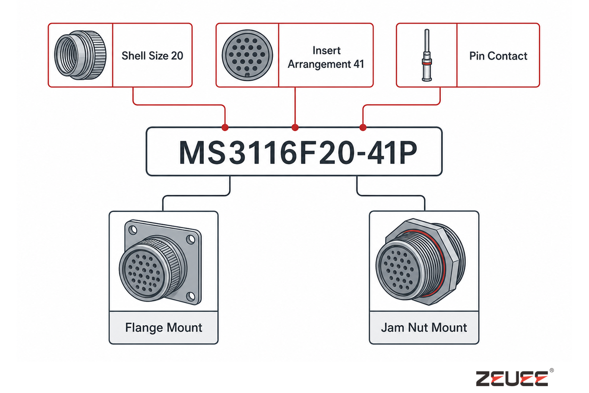
A MIL-DTL-26482 part number includes series/style, shell size, insert arrangement, contact gender, and finish in a consistent fixed order, shown in the following breakdown of an example part number, MS3116F20-41P: MS3116 is the main part-family prefix of this connector style. F refers to the Shell/Coupling Style Variation within the family. 20 is the shell size. 41 is the Insert Arrangement Code (this can be cross-referenced with the Insert Arrangement Table specific to the shell size called out in position 4). P in the final position designates the contact gender (pin).
Two mounting options exist on the receptacle half: (1) flange-mount – available in both narrow and wide flange bolt patterns for bulkhead or panel mounting; and (2) jam nut mounting – a single nut threaded onto the extended boss penetrating a bulkhead used when space around the connector on the panel side is limited. Both mounting options pass through the same thru-bulkhead penetration, and choosing between them depends only on existing panel support, bolt pattern, and available physical space — there’s no electrical or environmental performance difference.
| Field | Value in example | Meaning |
|---|---|---|
| Base prefix | MS3116 | Connector style family |
| Style letter | F | Shell/coupling style variant |
| Shell size | 20 | Physical shell size, sets contact capacity |
| Insert arrangement | 41 | Contact count/layout code for this shell size |
| Contact gender | P | Pin (mates to a socket contact on the opposite half) |
This field-by-field numbering scheme is defined directly in the base MIL-DTL-26482 specification maintained by the Defense Logistics Agency, so any part-number decode should ultimately trace back to that current revision rather than a distributor catalog’s shorthand.
MIL-DTL-26482 vs MIL-DTL-38999: Which Standard Fits Your Program?
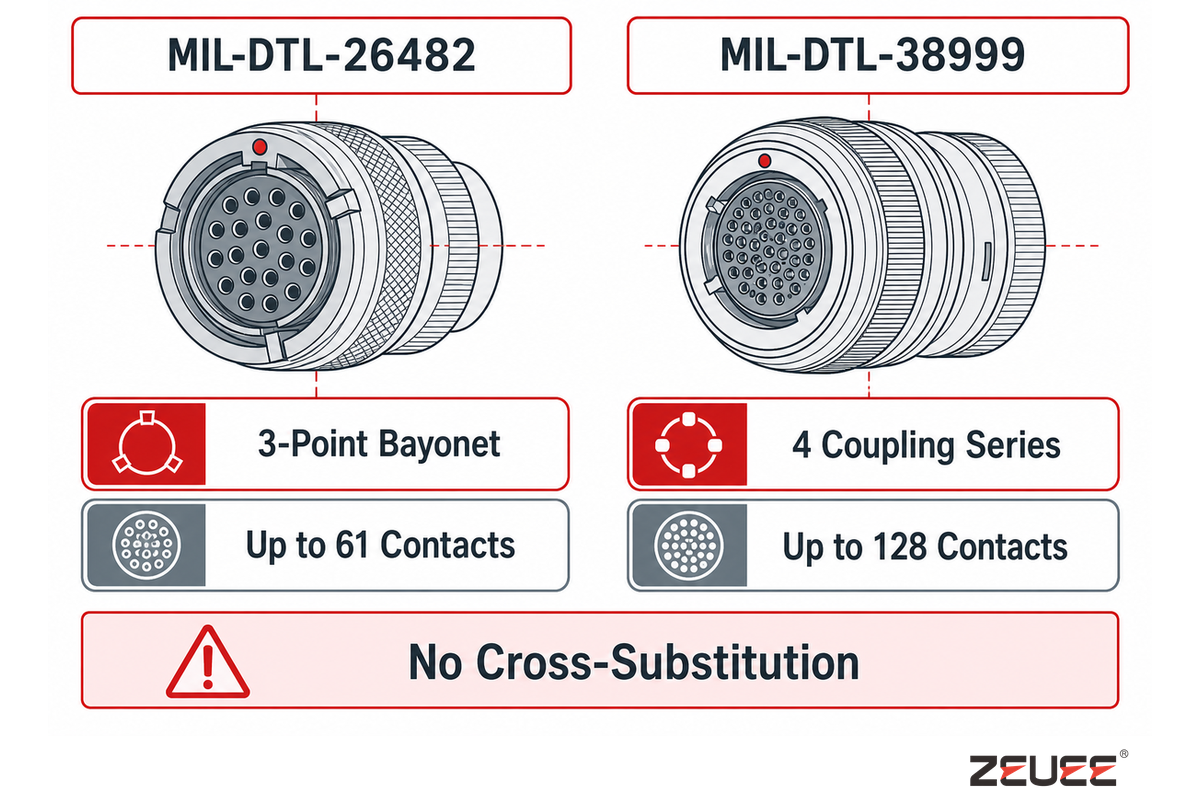
MIL-DTL-26482 and MIL-DTL-38999 are both DLA-maintained circular-connector detail specifications that diverge on coupling mechanism, maximum contact density, backshell detail-sheet family, and standard lineage. The older MIL-DTL-26482 bayonet design traces to the 1950s MIL-C-5015 family and is currently at Revision J with Amendment 2 (dated 2024-03-05).
MIL-DTL-38999 is the newer four-series standard, currently at Revision N with Amendment 1 (dated 2023), offering a choice of bayonet, threaded, triple-start, or breech-lock coupling depending on series.
| Dimension | MIL-DTL-26482 | MIL-DTL-38999 |
|---|---|---|
| Coupling type | Single design: 3-point bayonet | 4 series, each different (bayonet/threaded/triple-start/breech-lock) |
| Contact density (max) | Up to 61 contacts, shell 8-24 | Up to 128 contacts, shell #9-#25 |
| Backshell detail sheet | AS85049/8 (Series II only) + PT-style proprietary (Series I) | AS85049/17D, Category 2B (Series I/II) |
| Standard lineage / current revision | 1950s MIL-C-5015-derivative, Revision J + Amendment 2 (2024) | Later-generation standard, Revision N + Amendment 1 (2023) |
| Hermetic sealing option | MS3113 glass-to-metal (Series I only) | Hermetic glass-to-metal variant available family-wide |
| Qualification/QPL status | Active, independently DLA/ASSIST-qualified | Active, independently DLA/ASSIST-qualified |
Both standards remain active, DLA/ASSIST-qualified specifications with no cross-substitution: a compliant MIL-DTL-26482 part doesn’t satisfy a drawing calling out MIL-DTL-38999, and vice versa, even though the two standards’ shell-size ranges overlap around #9 through #24. Program era is often the practical deciding factor: MIL-DTL-38999, particularly Series III, is the more commonly specified standard on new-start high-vibration programs, while MIL-DTL-26482 remains active on legacy platforms and any new design where its specific backshell family or hermetic Series I option is already the established interface. For readers building a full comparison, our MIL-DTL-38999 connector guide covers that standard’s own series, part-numbering, and qualification detail in full.
Backshells and Accessories for MIL-DTL-26482 Connectors
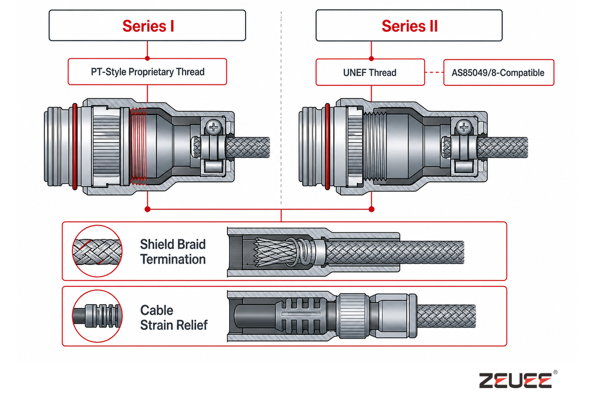
Selection of a backshell for a MIL-DTL-26482 assembly is series-specific and not universally interchangeable: Series II employs an AS85049/8 backshell that mates via a UNEF thread to a MIL-Spec connector. Series I, on the other hand, uses a proprietary, PT-style thread that isn’t supported by the AS85049 series, nor is the Series-I connector design covered by the AS85049/8 specification itself, which is scoped to MIL-C-5015 crimp, MIL-C-26482 Series 2, MIL-C-81703 Series 3, and MIL-C-83723 Series III connectors.
⚠️ Common Mistake
A frequently repeated error is assuming Series I and Series II accessory threads are interchangeable. They are not intermateable: Series I accessory threads can engage on fewer than three full threads at a modified major diameter, while Series II requires three full threads minimum with interlocking teeth. Forcing a Series II backshell onto a Series I shell (or the reverse) will not seat properly and produces marginal environmental sealing at best.
Beyond the issue of thread compatibility, the primary functions for backshells on this family of interconnect components are to provide a termination point for EMI shield braiding and to offer cable strain relief where the wires emerge from the connector shell, just as they do in all mil-spec circular connectors. An emphasis on proper specification of the backshell family prior to component design (and procurement of the connector shells) eliminates a time-consuming rework cycle later on as the backshell and connector shell thread set becomes a fixed decision point the moment the shell part number is chosen. SAE AS85049/8 formally defines Series II’s own backshell interface, the detail sheet referenced earlier for its UNEF thread and interlocking-teeth engagement.
Procurement and Qualification Requirements
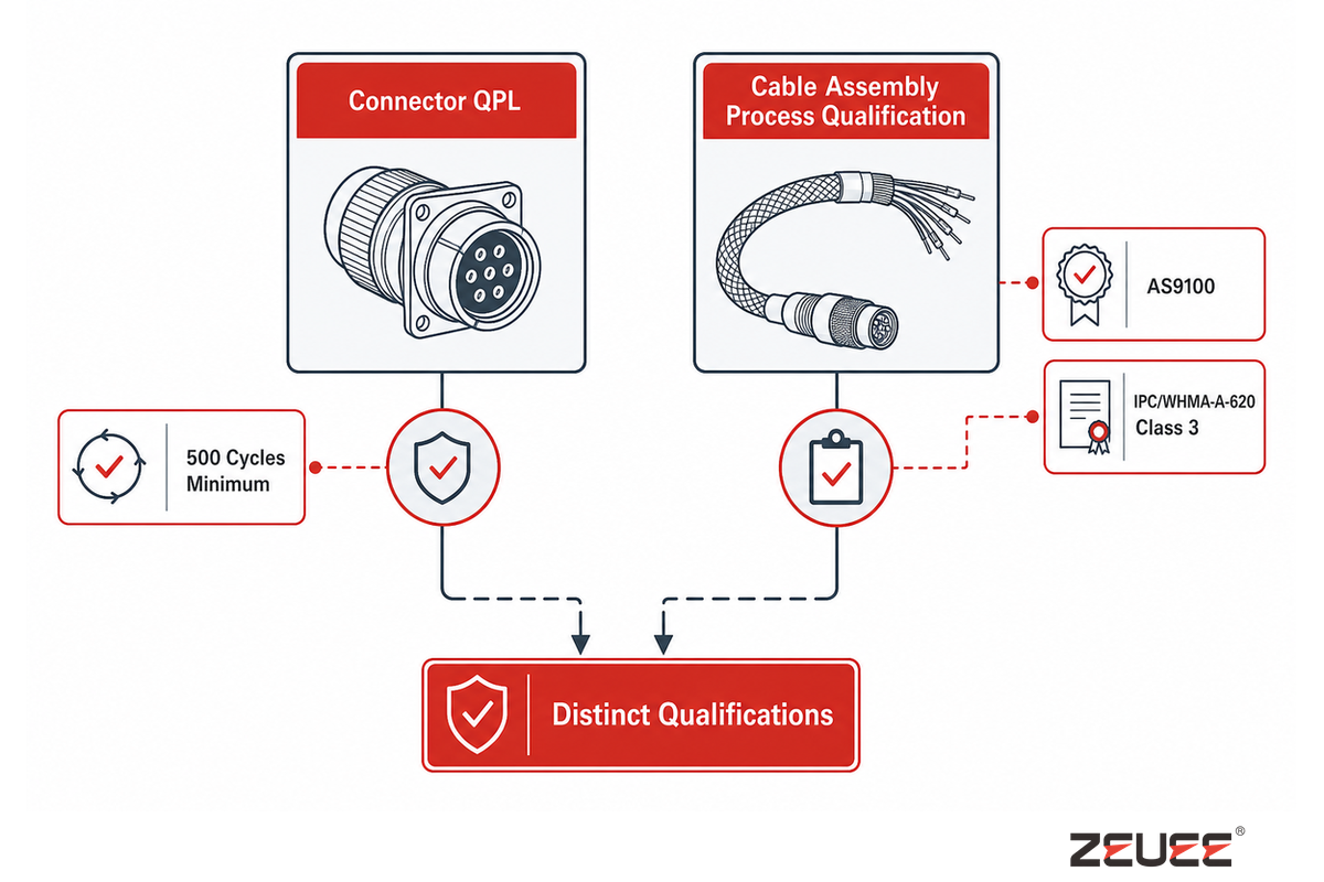
MIL-DTL-26482 connector and cable-assembly suppliers for aerospace and defense programs are typically expected to hold AS9100 certification and IPC/WHMA-A-620 Class 3 process qualification. That expectation isn’t limited to defense-only primes – commercial aerospace subcontractors supplying into the same aerospace and defense supply chains are generally held to the same certification bar. IPC/WHMA-A-620 Class 3 is the workmanship standard reserved for critical-use equipment in harsh environments, including aerospace environments and military applications. It requires destructive lot-sample pull-testing with a retained failure record and serialized traceability linking each finished assembly to its raw-material lot codes and certifying operator, with a typical seven-year record-retention window for that traceability data under AS9100 aerospace practice.
It’s critically important for program engineers to realize that a supplier’s own qualification to build MIL-DTL-26482-compliant connectors (which would be documented in a DLA/ASSIST QPL listing referencing the base MIL-DTL-26482 specification) and a downstream cable-assembly shop’s process qualification to IPC/WHMA-A-620 Class 3 are distinct qualifications, neither of which guarantees that the other is met.
RFQ checklist — copy these into your quote request:
| Parameter | Recommended range | Why it matters | How to verify |
|---|---|---|---|
| Series | Series I or Series II per 4-Gate Series Selector output | Wrong series breaks form-fit-function on the drawing | Cross-check part number prefix against drawing callout |
| Shell size | 8-24 per required contact count | Sets contact capacity and connector footprint | Confirm against insert-arrangement callout |
| Contact plating | Class L/A/G/W per environment | Corrosion resistance vs. conductivity tradeoff | Request plating-class certificate of conformance |
| Backshell family | AS85049/8 (Series II) or PT-style proprietary (Series I) | Wrong backshell breaks EMI shielding continuity | Confirm against drawing note, not just part number |
| Supplier certification | AS9100 + IPC/WHMA-A-620 Class 3 | Common acceptance expectation in aerospace/defense programs | Request current certificate and last audit date |
| Mating cycle rating | 500 cycles minimum | Governs field life under repeated mate/de-mate | Request test report or connector-saver log |
| Hermetic sealing (if required) | MS3113 glass-to-metal, Series I only | Only needed for moisture/gas-ingress-critical housings | Request hermetic leak-test certificate |
Beyond the four plating classes already summarized in the checklist above, the base specification defines additional finish options – Classes E and H among them – for programs with corrosion, conductivity, or high-temperature requirements that fall outside the L/A/G/W baseline; specifying the wrong class letter on a drawing is a common source of RFQ rework. MIL-DTL-26482’s base shell part number also anchors a family of associated standard sheets – MS3121, MS3122, and MS3124 among them – covering specific backshell and adapter configurations that a program’s bill of materials may call out separately from the connector shell itself. On the assembly floor, pin contact insertion and removal is its own qualified skill: crimp-style pin and socket contacts are designed to be inserted and extracted with dedicated tooling rather than pressed or pulled by hand, and getting that step wrong is a common source of bent-pin field failures downstream.
Typical Applications, Where MIL-DTL-26482 Connectors Are Used
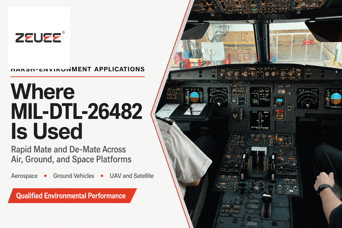
MIL-DTL-26482 connectors see continued use across aerospace wiring, ground-vehicle communication systems, and weight- or space-constrained platforms including UAVs and small satellites. Smaller shell sizes, including sizes 8 and 10, are a common fit for UAV and miniature-sensor platforms where every gram of connector weight competes directly against payload or flight-time budget. Series II can also reduce connector mass on weight-sensitive programs; for context, the shell-16 comparison above is roughly 12% lighter than the Series I equivalent. Space programs add a further wrinkle: hardware bound for vacuum chambers during qualification testing, and for on-orbit vacuum service afterward, needs outgassing and cold-weld behavior confirmed in addition to the base specification’s standard environmental testing.
Ground-vehicle communication systems favor this standard’s rapid mate/de-mate characteristic for field-serviceable equipment that gets connected and disconnected more often than a fixed airframe wiring run, where the bayonet’s quarter-turn lock is a genuine maintainability advantage over a threaded alternative. Aerospace applications more broadly rely on the connector family’s qualified environmental sealing and vibration performance to survive the same sustained-vibration, thermal-cycling conditions that drive most mil-spec connector selection decisions in the first place, on both military and commercial programs.
Beyond the connector’s own aerospace and defense core, ZEUEE — as a MIL-DTL-26482 assembly-equipment builder — ships to customers in 30+ countries. Its telecommunications, automotive, and industrial automation accounts are a reminder that the underlying cable-connection hardware and assembly know-how extends well beyond this one mil-spec designator.
📐 Engineering Note
Whether a shell-8 or shell-10 connector is used on an unmanned airborne system, or a shell-16 or larger connector is used in a ground-vehicle communications cable run, both follow the same base specification. The appropriate shell size depends on contact count and connector footprint together with the application’s electrical, environmental, shielding, and mounting requirements.
Where the Standard Is Headed, MOSA, SWaP, and Ground-Vehicle Demand
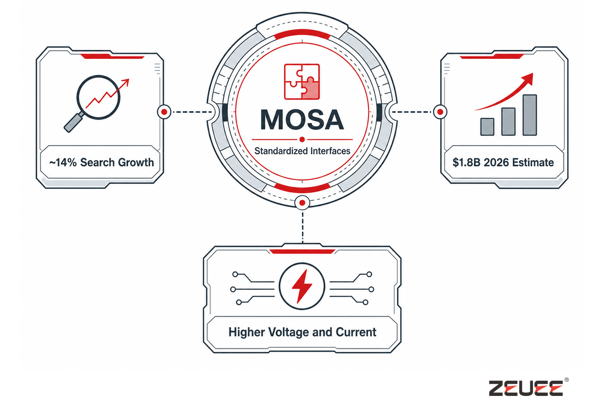
Search-related queries for the specific term “MIL-DTL-26482,” rather than the more generic “mil-spec connector,” have grown by roughly 14% (a ratio of about 1.14) compared with the prior 13-month period. That shift toward the specific, standards-centric name links to a structural factor: the Department of War’s November 2025 memorandum on a Modular Open Systems Approach (MOSA).
MOSA is named as a primary lever for “accelerating the speed of relevance” across all Major Defense Acquisition Programs, which are now directed to use a Modular Open Systems Approach “to the maximum extent practicable.”
U.S. Secretary of War memorandum, November 2025
MOSA’s emphasis on common, standardized interfaces extends to ground-vehicle systems. Growing vehicle electrification increases the need for interoperable actuator connectors and for components rated for higher voltage and current, including those used in Next Generation Combat Vehicle prototypes. An independent assessment of market size adds corroborating evidence: the ground-vehicle-actuators sector is expected to reach roughly $1.8 billion by 2026. The MOSA mandate, however, is the stronger demand signal because a federal requirement carries more weight than a valuation estimate from a single market-research firm.
~14%
“MIL-DTL-26482” search growth, recent comparison window
Declining
Broader generic mil-spec-connector search category
$1.8B
Ground-vehicle-actuators market, 2026 estimate
From Connector Standard to Production, Where Automated MIL-DTL-26482 Assembly Fits

Once a program has settled on shell size, series, and part number, the remaining question is how those connectors actually get assembled into finished cable harnesses at production volume. A process capable of handling MIL-DTL-26482’s full shell-size range (8 through 24) and both Series I and Series II termination styles — solder, front-release crimp, and rear-release crimp — needs tooling changeover fast enough that switching between configurations does not become the production bottleneck.
Inconsistent torque application across that shell-size range is a common failure point in mixed-volume production: a coupling ring torqued below spec risks vibration-induced back-off in the field, while over-torque on a smaller shell-8 or shell-10 connector can deform the shell body or gall the coupling threads. A production cell running shell-8 UAV connectors alongside shell-16-and-larger ground-vehicle assemblies in the same shift needs tooling that repeats accurately across that whole range without a manual recalibration step between changeovers — the failure mode usually shows up downstream, in random-vibration or thermal-cycling qualification testing, not on the assembly line itself.
ZEUEE builds purpose-built MIL-DTL-26482 assembly equipment covering this shell-size and series range, with closed-loop torque control and series-specific tooling changeover built into the station design. For programs evaluating whether a manual or automated process fits their production volume, that page covers the equipment side of the decision in the depth this guide deliberately does not — this article’s scope is the connector standard itself, not a specific machine’s configuration or cost breakdown.
Frequently Asked Questions
Q: What is MIL-DTL-26482?
MIL-DTL-26482 is a U.S. military detail specification document for circular, bayonet-coupled electrical connectors, maintained by the Defense Logistics Agency and available in two active series.
MIL-DTL-26482 covers circular, bayonet-coupled electrical connectors and is maintained by the Defense Logistics Agency. It has two active series, Series I and Series II, which differ in contact termination, accessory interfaces, and operating-temperature range.
Both series use the base specification’s shell-size range of 8 through 24 and support up to 61 contacts, depending on the insert arrangement. The connector family traces to the 1950s and an older MIL-C-5015 threaded-coupling lineage.
Q: What does “MIL-DTL” mean?
“MIL-DTL” stands for Military Detail Specification, the U.S. Department of Defense document format that specifies exact design, dimensional, and performance requirements for a hardware item.
MIL-DTL means Military Detail Specification. Unlike a performance specification that states required outcomes while allowing design flexibility, a detail specification defines design features, dimensions, materials, and performance requirements. The Defense Logistics Agency maintains MIL-DTL-26482 for the Department of Defense.
The specification and its amendments are listed in the ASSIST document-management system, where current revisions are made publicly available.
Q: What is MIL-DTL-26482 Series 2?
The Series II variant of MIL-DTL-26482 is rear-release-crimp only, rated to a wider -65°C to +200°C operating range and a higher vibration threshold than Series I.
MIL-DTL-26482 Series II is the rear-release-crimp-only variant of the standard, rated to a wider -65°C to +200°C operating range and a higher vibration threshold than Series I, while also running roughly 12% lighter on an equivalent shell size. It uses UNEF-threaded, AS85049/8-compatible backshells rather than Series I’s proprietary PT-style thread, and it does not offer the hermetic MS3113 sealing option available on Series I.
Q: What are crimp terminals?
Crimp terminals are electrical contacts mechanically compressed onto a stripped wire end using a specified crimp tool, positioner, and die combination, rather than joined by solder.
A crimp terminal is an electrical contact mechanically compressed onto the stripped end of a wire using the prescribed crimp tool, positioner, and die set rather than joined by solder. This differs from a solder type contact. MIL-DTL-26482 connectors use crimp contacts qualified to SAE AS39029. A crimp can look acceptable even when the wrong positioner or die was used for the contact and wire-gauge combination, so visual inspection alone does not replace a pull-force test.
Q: What is a MIL-DTL-28748 connector?
MIL-DTL-28748 is a separate rectangular/rack-and-panel mil-spec connector family, distinct from the circular MIL-DTL-26482 and MIL-DTL-38999 standards covered in this guide, and it should not be substituted on a drawing or bill of materials.
MIL-DTL-28748 is a separate rectangular/rack-and-panel mil-spec connector family, distinct from the circular MIL-DTL-26482 and MIL-DTL-38999 standards covered in this guide. It is worth knowing about mainly to avoid confusing it with either circular standard on a drawing or bill of materials — the shell geometry, mounting style, and typical application (rack-and-panel blind-mate) differ substantially from a circular bayonet or threaded connector.
Q: What are the different types of MIL STD connectors?
MIL STD connectors span several distinct families, including MIL-DTL-26482, MIL-DTL-38999, and MIL-DTL-5015, each with its own coupling type and shell/contact system that is not interchangeable with the others.
Military connector specifications define separate families with different coupling mechanisms, shell geometries, and contact systems. These families are not automatically interchangeable. Common examples include MIL-DTL-26482, MIL-DTL-38999, and MIL-DTL-5015; the governing drawing determines which family applies.
Q: What are the different types of military connectors?
Military connectors span circular bayonet and threaded families (MIL-DTL-26482, MIL-DTL-38999, MIL-DTL-5015), rectangular rack-and-panel families (MIL-DTL-28748 and similar), and specialized RF, fiber-optic, and hybrid-contact variants built to their own detail specifications.
Military connectors span circular bayonet and threaded families (MIL-DTL-26482, MIL-DTL-38999, MIL-DTL-5015), rectangular rack-and-panel families (MIL-DTL-28748 and similar), and specialized RF, fiber-optic, and hybrid-contact variants built to their own detail specifications, each qualified for a different combination of coupling speed, contact density, vibration environment, and mounting style. The right family for a given program depends on which of those attributes the application prioritizes — a rapid-disconnect, tool-free coupling need points toward a bayonet family like MIL-DTL-26482, while a high-contact-density, high-vibration application more often lands on a threaded or triple-start standard like MIL-DTL-38999. No single family “wins” universally; the drawing and the application requirements determine which specification governs a given connector position.
About This Analysis
This guide draws on the current DLA base specification and revision history, SAE crimping and backshell standards, manufacturer primary-source data (Amphenol Aerospace), and public federal-acquisition and market data, cross-checked against ZEUEE’s own MIL-DTL-26482 shell-size and platform-mix observations from building connector-assembly equipment for this standard. The Series I/II operating-temperature figures in this guide were independently verified against manufacturer publications rather than repeated from a secondary source.
References & Sources
- MIL-DTL-26482 Specification Listing Defense Logistics Agency
- MIL-DTL-26482H Full Text EverySpec (DLA mirror)
- SAE AS85049/8 Backshell Standard SAE International
- Self-Locking Bayonet Coupling Mechanism US Patent 6,226,068 B1
- Modular Open Systems Approach (MOSA), 10 U.S.C. § 4401 Acquisition.gov
- IPC/WHMA-A-620 Class 3 Certification Jusco
Related Articles
- MIL-DTL-38999 Connector Machine Guide series, standards, and assembly for the sibling circular-connector standard
- Connector Crimping Machine Guide crimp termination equipment context
WHY WE WRITE THIS
About ZEUEE Engineering Insights
ZEUEE shares technical guides based on real automation project experience. Since 2005, we have designed and manufactured non-standard automation equipment for connector assembly, wire harness production, robotic lines, vision inspection, and smart factory upgrades.
Founded in 2005
20,000 m² production base
120+ specialists
150+ R&D patents
ISO9001:2015 certified