Get in touch with Zeyu lntelligent Industrial Company

Pin Insertion Machine Guide: 7 RFQ Checks
Pin Insertion Machine guide for process window risks, force checks, feeder choices, traceability, and RFQ data before custom automation scoping.

Connector Assembly Automation Guide
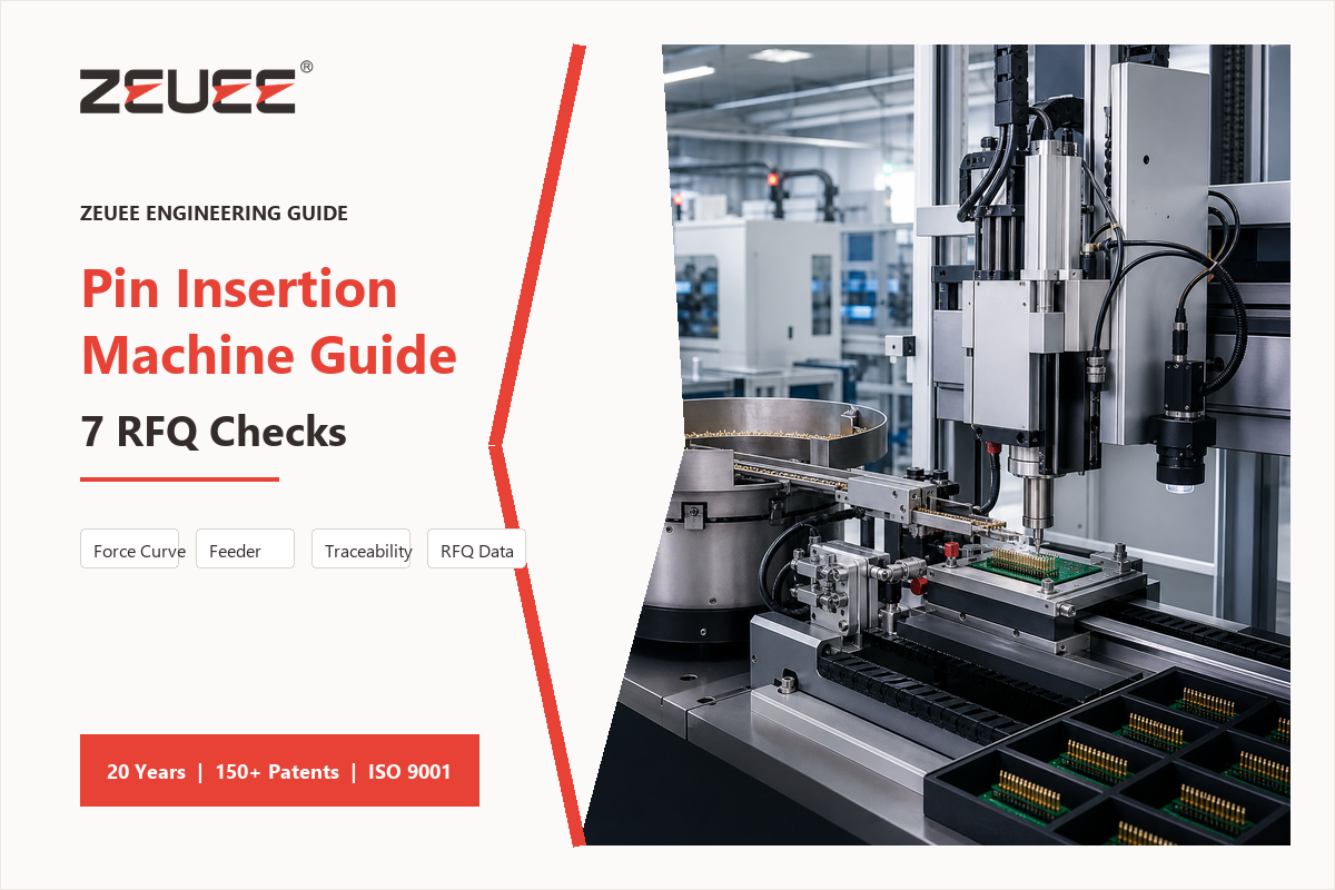
A Pin Insertion Machine automatically feeds, locates, presses into a part, and inspects pins, compliant contacts or other terminals after they’re seated. This guide explains the process window and buying checks behind such machines without taking the place of a custom machine scope or quote discussion.
What Is a Pin Insertion Machine?
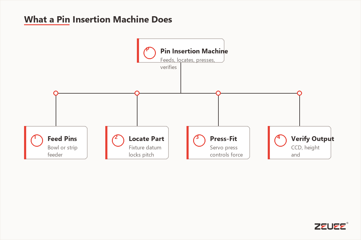
A pin insertion machine is an assembly station that presses pins into a PCB, connector housing, lead frame, coil frame or similar component using precise alignment and force control. The question for your purchase team isn’t simply can it push in a pin? it’s whether it can maintain the press-fit process window across real parts, real tolerances and real production changes.
Buyer check: The hidden risk is a fixture or feeder problem that looks like a machine problem because the first sample set is too clean. For automotive assembly or production fixture reviews, ZEUEE engineers can compare sample lots, a 10 mm datum check, and a 30 sec inspection cycle against precision ISO 9001 certified review steps.
For press-fit connector work, the baseline technical context is solderless press-in connection practice. IEC 60352-5:2020 describes press-in connections as a termination with a suitable press-in zone inserted into a board hole, and it includes test methods and practical guidance for stable electrical connections.
The automation side is much broader, and NIST places robotics efforts around performance, safety, agility, autonomy, and ease of implementation for manufacturing systems. In the context of pin insertion, it means your feeder, fixture, insertion head, sensor suite, and traceability approach will all be evaluated before you add a new machine to the line.
4-Stage Pin Insertion Loop
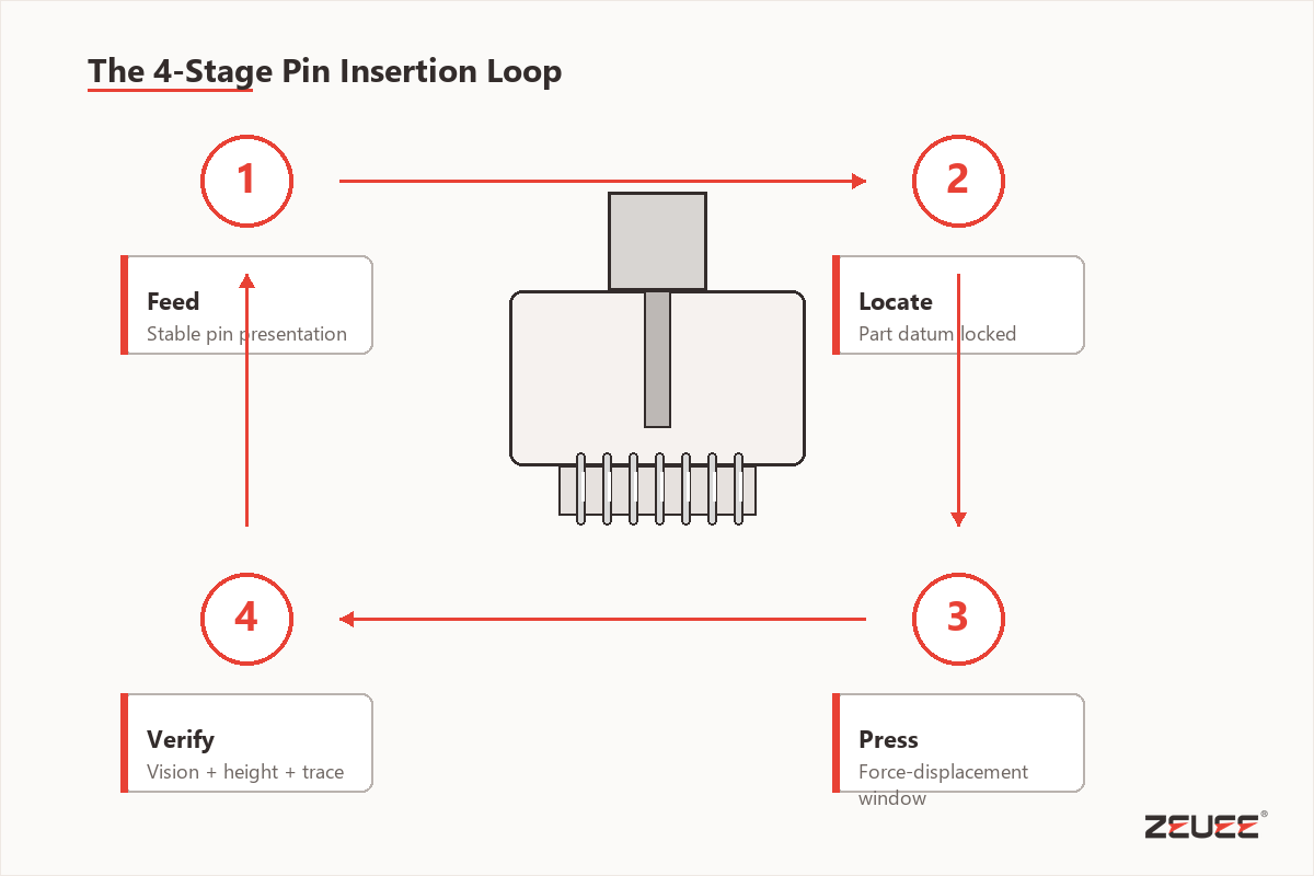
The 4-Stage Pin Insertion Loop: How to Buy the Machine Feed the pin. Support the part securely. Press within the force window. Inspect. Every element in this process affects the other stages, and if any step falters, the defects often show up in the following stage.
Feeder check: A common challenge is treating feed, support, press, and inspection as separate stations when the root cause is structural. In a production assembly use case, ZEUEE engineers review feeder risk, fixture precision, ISO 9001 documentation, and a 30 sec trial cycle before judging line speed.
1. FeedSort or present pins from reel, bowl, tube, tray, or custom feeder without burr buildup, mixed orientation, or jam-prone transfer.
2. StabilizeSupport the PCB, plastic housing, or carrier so the hole location and part datum do not move during actuation.
3. PressUse a pin insertion head, tool, or actuator to control stroke, speed, and required insertion force.
4. VerifyCheck pin height, presence, polarity, force-displacement curve, and traceability data before the part moves on.
For example, a bad feeder can create gaps that will leave a high-speed insertion head waiting. A flimsy fixture can introduce vibrations that make your good insertion head look bad in a force plot. Skipping inspection at the press can send bent pins to other, more expensive test stages, like functional test, where rework is much more expensive.
Manual vs Semi-Automatic vs Fully Automatic Pin Insertion
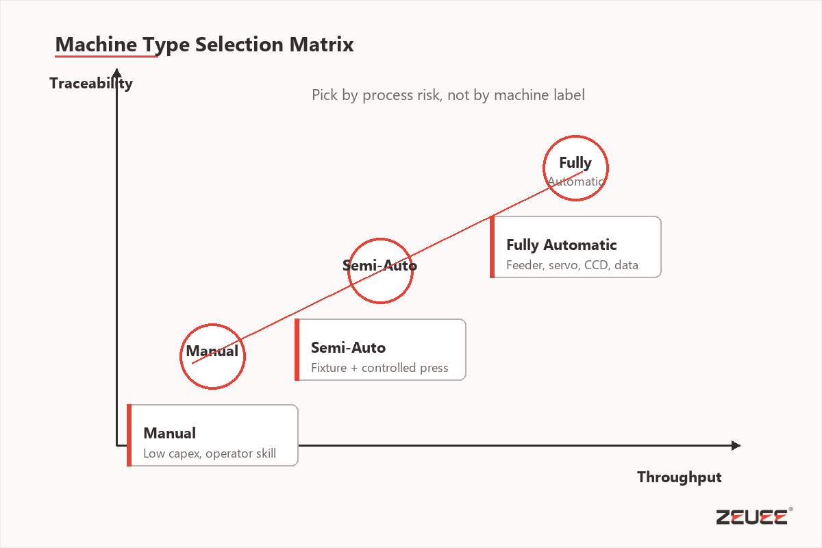
A manual press, semi-automated station or fully automated system could be the right tool for the job. What matters is how you rank the production requirement in the order of volumes, variants, process robustness, on-line inspection, or traceability.
Automation check: The tradeoff is not manual versus automatic; the real risk is inconsistent output because the wrong automation level was chosen. For automotive, electronics, or OEM assembly, ZEUEE engineers compare fixture precision, ISO 9001 review records, and a 1 hour changeover test before recommending a machine category.
| Method | Best Fit | Operator Role | Inspection Depth | Main Risk |
|---|---|---|---|---|
| Manual pin insertion tool or bench press | Prototype, repair, low-volume work, simple pin geometry | High. Operator feels alignment and controls each insert. | Usually visual or gauge-based after insertion. | Variation between operators and fatigue over repeated work. |
| Semi-automatic pin insertion system | Moderate volume, frequent changeover, partial feeder automation | Loads parts, starts actuation, may respond to alarms. | Presence, height, and limited force checks can be added. | Fixture or feeder limits can hide behind acceptable cycle time. |
| Fully automated pin inserters | Stable high-volume production, inline PCB assembly, connector assembly line | Monitors machine status and replenishes material. | Force-displacement, CCD inspection, barcode, and traceability are practical. | Bad inputs scale quickly if the process window was not validated. |
Bead Electronics makes the good point that in the context of their press-fit connector work, manual assembly isn’t the enemy of automation. Small part sizes, low volumes or variability that benefit from operator interpretation still make sense to be assembled by hand or using simple aids, rather than a full machine. Start the process with an assessment of your assembly risk, then look for equipment.
Press-Fit Process Window
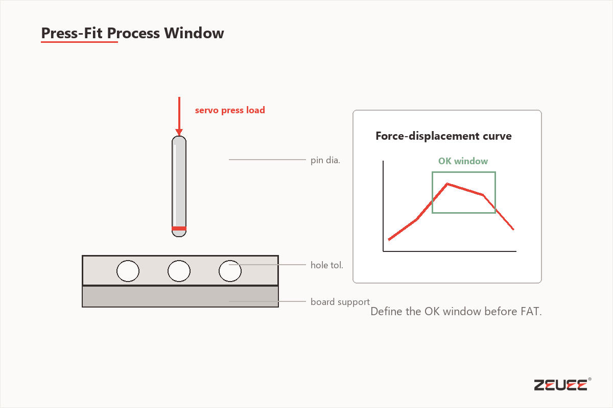
The press-fit process window represents the acceptable operational envelope for pin size and shape, hole tolerance, board thickness and support, plating, press-stroke, and applied force that ensures reliable electrical connection without board damage or excessive stress/retention variations.
| Variable | What To Check Before Machine Design | Why It Matters | Evidence Cue |
|---|---|---|---|
| Pin diameter and press-fit zone | Nominal size, tolerance band, compliant section shape, plating finish | Small geometry differences change the required insertion force. | IEC 60352-5:2020 scope and press-in connection definition |
| Hole tolerance and board stack | Drill, plating, copper thickness, material, support points | Hole variation shifts insertion force and retention behavior. | IEC 60352-5:2020 update notes include copper thickness and force graphs |
| Board or housing support | Fixture datum, backup plate, local stiffness, part seating | Deflection can bend pins or make a good actuator look unstable. | Assembly Magazine discusses PCB and connector alignment context |
| Stroke and speed | Start height, final height, approach speed, press speed, retract path | The same pin can behave differently when speed and support change. | Circuits Assembly reports 100 mm/s insertion testing |
| Insertion force profile | Peak force, force-distance curve, final force, push-out or retention check | Force curve shape reveals undersized holes, blocked holes, bent pins, or poor seating. | Circuits Assembly reports a 96.4% model fit for insertion-force factors |
| Verification method | Pin height, missing pin, polarity, CCD, sensor confirmation, barcode link | Verification converts an insertion station into a controlled manufacturing process. | Autosplice lists force measurement, barcode, and tool protection options |
| Changeover | Variant count, feeder swap, tool change, recipe management | A fast machine with slow changeover can lose the productivity case. | FUJI highlights versatility and maintenance as automation concerns |
| Traceability | Part ID, recipe ID, force record, alarm reason, operator action | Traceability helps separate material drift from machine drift. | NIST frames manufacturing automation around measurement science |
| Rework boundary | Allowed reinsertion, inspection after rework, board history | Blanket rules are weaker than measured retention and force evidence. | Circuits Assembly reports rework amount was not the dominant factor in its data set |
Perhaps the most surprising finding from a Circuits Assembly study of press-fit connector rework processes was that factors like the type of pin and the hole dimensions played a greater role in the insertion force curves than repeated reworking of failed assemblies. While this doesn’t diminish the importance of the insertion force profile itself, it highlights the value of building good part quality into the upstream process as much as possible.
Specification Snapshot For Early Scoping
These aren’t ZEUEE machine claims. They’re public benchmarks from equipment and press-fit test sources that help your team ask smarter questions before you scope a pin insertion system.
| Reference Point | Reported Figure | How To Use It In RFQ Discussion |
|---|---|---|
| Autosplice insertion area example | 250 mm x 250 mm | Compare against actual part nest size and travel needs. |
| Autosplice cycle reference | 0.7 sec/component | Ask whether feeder, inspection, and unload keep up with insertion. |
| Autosplice utility reference | 6 bar air | Confirm factory air capacity and pressure stability. |
| Autosplice electrical reference | Supplier-specific current datasheet | Confirm voltage, frequency, current, safety category, and regional electrical assumptions with the supplier before layout approval. |
| Autosplice footprint reference | Supplier-specific current drawing | Confirm machine envelope, maintenance access, material loading space, and reject handling against the current drawing. |
| Circuits Assembly insertion test context | Published study context | Separate lab test context from production acceptance rate. |
| Circuits Assembly insertion-force model | 96.4% | Shows why pin, board, and hole variables deserve measurement. |
| Reported insertion-force variance share | 84%, 9%, 4%, 3%, 0% | Use as a reminder that one variable rarely explains every failure. |
| Reported retention-force variance share | 60%, 21%, 7%, 7%, 5% | Ask how the supplier will validate retention after insertion and rework. |
7-Failure-Mode Map
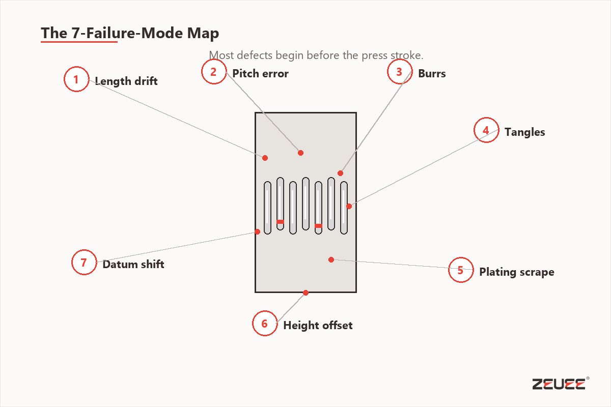
7-Failure-Mode Map is a troubleshooting table for pin insertion yield loss. It links visible defects to the part, feeder, tooling, fixture or verification step most likely to be responsible for the defect.
Defect check: Defect mapping fails when burr, pitch drift, or alignment risk is recorded only as a reject count. ZEUEE engineers use sample inspection, precision fixture review, ISO 9001 traceability, and a 10 mm datum check to separate tooling problems from material problems in production assembly.
| Failure Mode | Common Symptom | Likely Root Area | Practical Check |
|---|---|---|---|
| 1. Inconsistent pin lengths | Uneven final height or missed seating | Incoming material, cut process, feeder presentation | Measure pin lengths before blaming the actuator. |
| 2. Pitch drift | Pin does not align with hole or housing feature | Carrier strip, reel tension, indexing, fixture datum | Check pitch at feed exit and at insertion point. |
| 3. Burrs | High insertion force, scratched hole, partial seating | Pin cutting, plating, incoming material control | Add incoming sample inspection and force-curve alarms. |
| 4. Tangled or uneven winding | Feeder jam or skipped pin | Reel, tube, bowl feeder, transfer track | Run feeder-only trials before full machine trials. |
| 5. Sharp cutoffs | Plating scrape or board damage | Pin end condition and insertion tooling | Review cutoff geometry under magnification. |
| 6. Plating scrape | Electrical instability or poor retention | Hole size, pin finish, press path, board support | Compare force curve and post-insertion inspection. |
| 7. Hole or alignment mismatch | Bent pins, cracked housing, rejected PCB pin insertion | Fixture design, tooling wear, board tolerance, datum strategy | Verify datum repeatability before increasing press force. |
| 8. Missing verification | Bad parts escape to electrical test | Sensor plan, CCD coverage, traceability design | Define pass/fail criteria before automation purchase. |
| 9. Recipe mismatch | Good parts fail after changeover | Recipe control, operator selection, barcode link | Lock recipe, part number, and tooling ID together. |
Several of these failure modes are consistent with field problems reported by Bead Electronics, including pin-length variation, pitch problems, burrs, winding, sharp cutoffs, and plating scrapes. The takeaway is obvious: if the root cause is feeder presentation, part quality, or hole alignment, a harder-pressing machine could actually worsen quality.
Feed-to-Force Bottleneck Chain
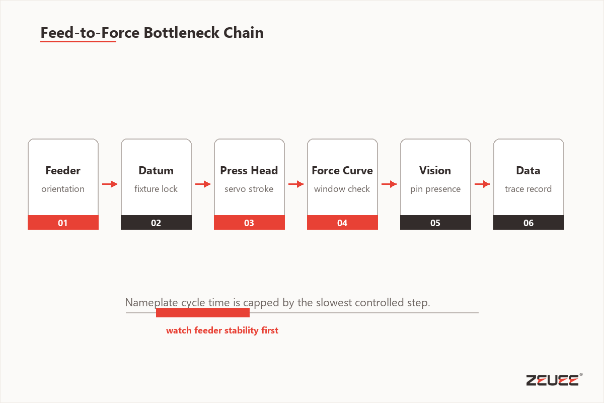
Feed-to-Force Bottleneck Chain. A pin insertion system’s actual cycle time is limited by the slowest stable operation between feeding material, presenting the part, actuating the insertion head, confirming force, and unloading the completed assembly. Nameplate speed only applies after this chain is stable.
Cycle check: A hidden delay often appears because the feeder or fixture cannot support the advertised press speed. In practice, ZEUEE engineers test production assembly flow with high-precision tooling, ISO 9001 records, a 30 sec inspection cycle, and at least 1 hour of stable material feeding.
Equipment pages commonly show machine options, such as insertion area, head count, tool protection, barcode scanning, remote control, force verification and in-line configuration. These details matter, but don’t tell the full story. A machine with an express actuator may sit idle waiting for feeder jams to clear. Long manual seating of the fixture may not meet production requirements. If verification takes too long, it can limit the output rate to inspection-speed. A vibratory feeder can make automatic pin inserters look fast in a demo, but the accepted-output metric should be good assemblies per hour, not cycles per second.
Practical rule: evaluate cycle time as stable output per accepted part, not strokes per second alone. For production efficiency, the denominator is good assemblies, not actuator motions.
Engineering teams should conduct feeder trials, fixture trials, and force-window trials prior to finalizing machine configuration. A modular pin insertion system may be beneficial in product family changeovers, but only if tooling and recipes can be quickly adjusted without creating new downtime events.
Force Curve Triage and In-Line Inspection
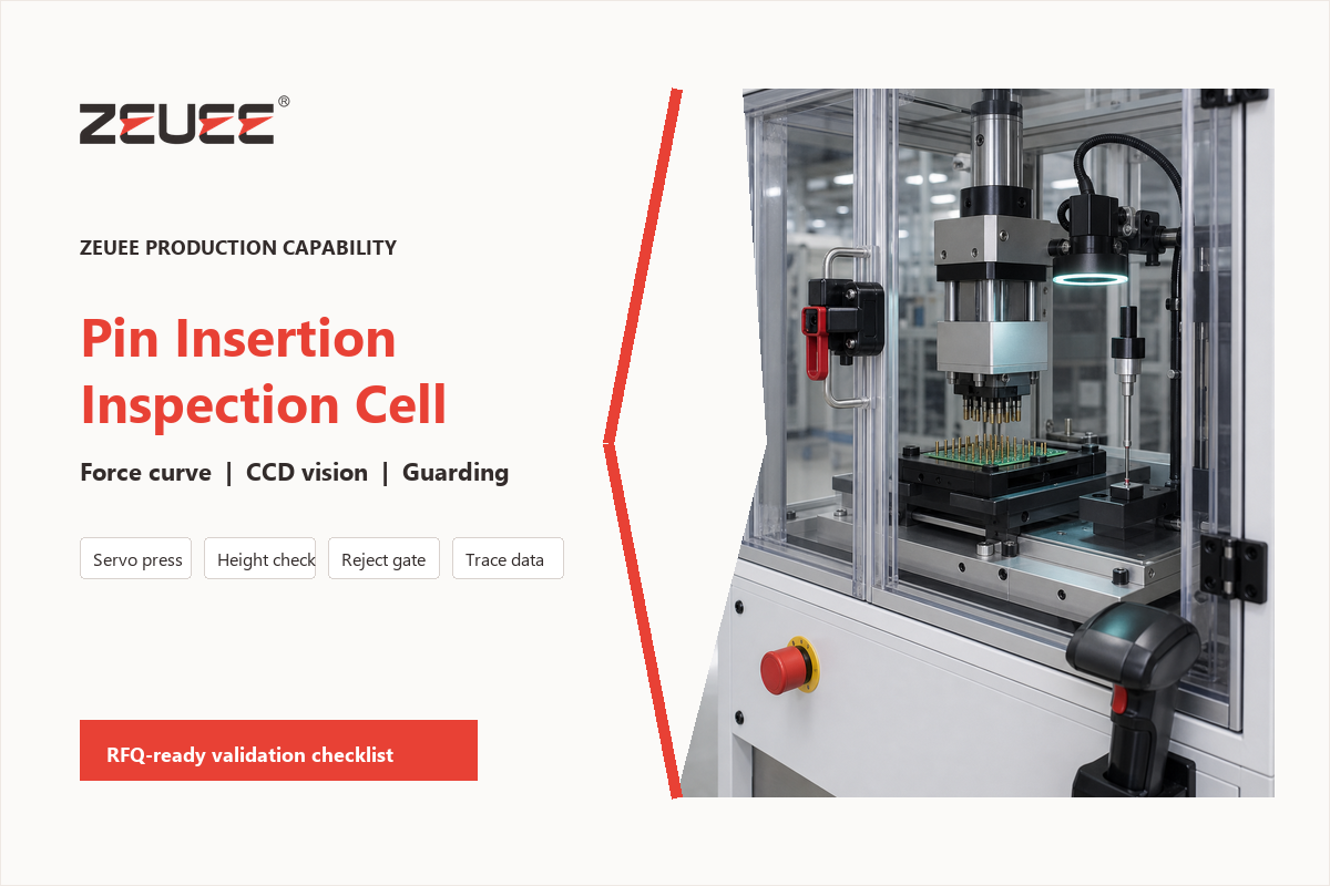
Force Curve Triage transforms force-displacement data into decisions. Instead of simply measuring peak insertion force, the station evaluates curve shape, final height, and inspection result to determine acceptance, rejection, rework or further investigation.
Inspection check: Force data becomes weak evidence when the root cause is missing from the sample plan. For PCB assembly or automotive production, ZEUEE engineers pair published test-context source notes with precision fixture checks, ISO 9001 review discipline, and a 30 sec visual verification cycle. For a printed circuit board line, specify whether the insertion force monitoring system records peak force, curve shape, final height, and station-level traceability.
| Signal | What It Can Reveal | Likely Action |
|---|---|---|
| Low force, correct final height | Possible oversized hole or weak retention | Review hole tolerance and retention test plan. |
| High force before seating | Burr, undersized hole, blocked path, pin angle | Stop and inspect pin, hole, and guide tooling. |
| Sudden force drop | Pin buckle, board damage, fixture slip | Reject part and inspect support surface. |
| Correct peak force, wrong final height | Stroke setup or datum error | Check recipe, datum, and pin insertion head setup. |
| Correct curve, missing pin image | Sensor or feeder discrepancy | Compare CCD result with feeder count. |
| Pin present, polarity wrong | Orientation fault in feeder or transfer | Add orientation check before actuation. |
| Repeated alarms after changeover | Wrong tooling, wrong recipe, variant mismatch | Lock barcode, tooling ID, and recipe together. |
| Slow drift over a shift | Tool wear, feeder contamination, material lot change | Trend force data by lot and maintenance interval. |
| Good force, failed electrical test | Contact zone, plating, board damage, downstream issue | Pair force data with electrical and visual evidence. |
Recent research in continuous pin insertion machines incorporates pressure, displacement, and force-displacement sensors within the machine model. This research addresses a key customer question: “ Will the vendor supply mechanical actuation alone or also furnish inspection data I can use to diagnose failure?”
Machine Safety And Standards Checks
A pin insertion station is powered production equipment, not simply a quality-control process. U.S. buyers should include guarding, point-of-operation access, jam clearance, maintenance access, and energy isolation in their acceptance checklist.
Safety check: Safety risk is expensive to fix after installation because guards, access doors, and feeder-clearing routines affect the machine layout. ZEUEE engineers can review production fixture access, precision stop positions, ISO 9001 documentation, a 15 min guarded run, and a 15 min maintenance simulation before FAT.
OSHA 1910.212 addresses “general requirements for all machines.” Specifically, this regulation requires machine guarding to protect operators and adjacent workers from hazards including the point of operation, in-going nip points, rotating parts and flying material.
In a pin insertion cell, this equates to considering machine guards, interlocks, two-hand controls, access for loading material and procedures for jam clearing without exposing hands or body parts to a hazardous area.
OSHA 1910.147 brings a separate servicing and maintenance lens. It covers the control of hazardous energy during servicing or maintenance, including the situation where an employee removes or bypasses a guard or reaches into a point-of-operation area. That’s relevant for feeder jams, tool changes, fixture adjustments, and routine maintenance.
For high-reliability electrical connector work, do not just consider IEC 60352-5:2020 the only option for an acceptance reference. On IPC’s automotive and e-mobility standards page, it states that IPC-9797 is a press-fit standard for automotive and other high-reliability applications and IPC-HDBK-9798 is the handbook for this standard. Check with your end customer what family of standards governs the acceptance, rework and qualification evidence.
Scope limit: IEC 60352-5:2020 is centered on press-in connections with a termination inserted into a board hole. Plastic housings, lead frames, coil frames, spring pin work, and other non-board applications need their own retention, fixture, and reliability checks instead of borrowed PCB assumptions. For acceptance, add a 15 min guarded production run and a 15 min maintenance-access simulation to the safety review.
Application Fit by Assembly Type
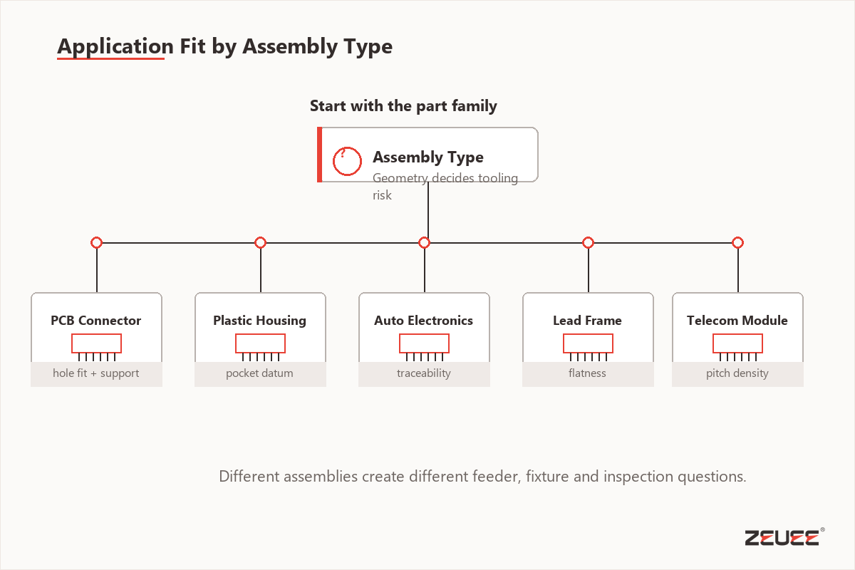
An automated pin insertion machine to assemble PCB connectors isn’t the same problem to engineer as a station to insert spring pins into plastic housings, leaf frames, coil forms or automotive electronic devices. The same word “pin” could mean many things regarding feeding, fixturing, inspection and compatibility.
Application check: The mistake is assuming every pin use case shares the same fixture or insertion head. For automotive, medical, electronics, and OEM production applications, ZEUEE engineers compare sample drawings, precision tooling, ISO 9001 review steps, 10 mm access limits, and a 30 sec verification check.
| Assembly Type | Typical Pin Insertion Question | Tooling Implication | Inspection Priority |
|---|---|---|---|
| Printed circuit boards | Can the board hole, press-fit zone, and support plate hold the process window? | Board support and force monitoring are central. | Pin height, force curve, and board damage. |
| Plastic connector housings | Will the housing deform, crack, or shift during insertion? | Fixture datum and controlled actuation matter. | Terminal position, retention, and housing damage. |
| Automotive electronics | Can the station provide traceability and repeatable verification? | Barcode, recipe lock, and inspection records become important. | Lot traceability and defect containment. |
| Telecom and electronics modules | Can mixed pin lengths or high contact density be controlled? | Precision fixture, pin insertion head stability, and variant management. | Presence, spacing, height, and force limits. |
| Coil frames and lead frames | Can thin or flexible carriers stay stable under force? | Local support and gentle transfer become design drivers. | Position, bend, and final seating. |
| Spring pin or roll pin work | Is the part being pressed into a mechanical bore rather than an electrical contact hole? | Different insertion tool, actuation, and retention logic. | Depth, perpendicularity, and mechanical retention. |
Patent activity is another indication that pin insertion machine improvements are still in play. A Google Patents search dated 2024 yields a “Pin Insertion Machine With a Pin Pushing Assembly”, confirming the continued design evolution around feeding, pressing and positioning mechanics.
Price Drivers Without Turning This Into a Quote Page
The price of a pin insertion machine is less about the keyword used and more about the workcell it’s part of: feeder complexity, pin design, station count, inspection complexity, output rate goal, changeover time goal, and data integration capabilities. A generic price estimate without the appropriate engineering drawings and pin samples will likely be unhelpful.
Cost check: Quote risk increases when the hidden problem is feeder variation, fixture wear, or missing inspection data. ZEUEE engineers can turn the cost discussion into a production assembly test plan with precision drawings, ISO 9001 review discipline, a 1 hour sample run, and a 30 sec reject-handling check.
For your purchasing department, the relevant question isn’t “What’s the lowest cost automatic pin insertion machine?” The key question is, “What can be eliminated from the system’s cost drivers before the supplier’s design begins?” A basic single-pin, single-part station has a vastly different budget profile than a full-scale production line with a multitude of heads, full CCD inspection, force-displacement analysis, defective-part sorting, and production data logging to MES.
- Feeder difficulty: (e.g., reels, tubes, trays, bowl feeders, mixed-orientation parts, presence of burrs or fragile leads)
- Pin-and-hole tolerance: (more stringent tolerances require tighter control of tooling, pressing forces, and process validation)
- Number of stations: (single-point insertion versus multi-point insertion on a PCB or multiple product variants)
- Inspection level: (e.g., visual, pin height and presence, polarity verification, force curve analysis, random sample testing of retention force, and lot traceability)
- Changeover method: (e.g., manual tooling changeovers for low-mix environments versus modular tooling and recipe management for frequent product variations)
- Integration into factory environment: (e.g., SMEMA protocol, MES connectivity, barcode reading, data output, reject bin management, and available floor space)
The most effective cost discussions are rooted in risk reduction. If a supplier requests drawings, sample pins, material tolerance specifications, a target throughput rate, and specific inspection criteria prior to providing a quote, this typically indicates a serious engineering approach rather than mere sales pressure. Before a pin insertion machine is even installed, the acceptance testing procedures should clearly outline expected good-part output, reject handling protocols, who will install the guards and fixtures, and the types of data you’ll be reviewing following your initial production run.
RFQ Readiness Stack
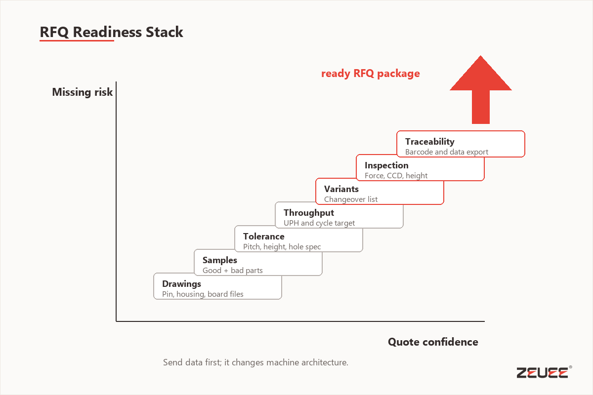
RFQ Readiness Stack: the information bundle required for an automation supplier to determine whether a project call for a simple manual fixture, a semi-automatic work station, a modular work cell, or a fully integrated production line.
RFQ check: The RFQ gap is not paperwork; it is risk control because missing tolerance, sample, or inspection data can send the project in the wrong direction. ZEUEE engineers use drawings, precision sample review, ISO 9001 traceability, a 10 mm datum reference, and a 30 sec cycle assumption to start the scope.
ZEUEE application engineering reviews typically begin with drawings, pin material, hole tolerance, target throughput, the inspection method, changeover limitations, and traceability. If that information is missing from the request, a quick quote can end up being far away from what the real process needs.
| RFQ Input | What To Send | What It Helps Decide |
|---|---|---|
| Part drawing | PCB, housing, carrier, or component drawing with datum and tolerance | Fixture design and support method |
| Pin specification | Pin diameter, length, press-fit zone, material, plating, packaging | Feeder, insertion tool, and force range |
| Hole or slot data | Nominal size, tolerance, plating, board thickness, material | Process window and inspection plan |
| Samples | Good parts, known-bad parts, sample reels or packages | Feeder trials and defect boundary testing |
| Output target | Parts per hour, shifts, acceptable downtime, yield target | Manual, semi-automatic, or fully automated configuration |
| Variant mix | Number of SKUs, changeover frequency, shared pin families | Modular tooling and recipe strategy |
| Inspection rules | Pin height, missing pin, polarity, force curve, retention, electrical test | Sensor, CCD, and data capture requirements |
| Factory limits | Floor space, power, air, upstream/downstream interface | Standalone vs inline layout and integration scope |
| Traceability needs | Barcode, MES, force record, alarm record, operator login | Data architecture and a 30 min steady-state acceptance trial |
Industry Outlook: From Pressing Pins To Measuring The Process
The real, practical evolution in automated pin insertion isn’t faster pressing. It’s a transition from mechanical to “measured” insertion-force feedback, vision verification, recipes, traceability, improved diagnostics-as production volumes of connectors and electronics soar.
Trend check: The future-facing risk is buying speed without measurement because production problems still need evidence. For electronics assembly and automotive production, ZEUEE engineers connect precision tooling, ISO 9001 review records, published test-context source notes, and 30 sec verification targets to traceable machine data.
Those same FUJI discussion points about their new automated insertion robot really highlight the concerns of almost all production teams: time crunch, labor gap, upkeep worries, and flexible production automation. As a result, many buyers now inquire about changeover, uptime, and system compatibility as much as high-speed pin insertion.
The standard’s context is also important. IEC 60352-5:2020 should not be seen as a brand sticker to place throughout any given paragraph but, rather, as a cue to question if the supplier knows how to implement press-in connections, what the best test method is, the behaviour under push-out, and how to address the contact area in a practical way.
When To Move From a Tool or Bench Press To a Custom Solution
If operator dexterity no longer compensates for the control of force, alignment, cycle time, inspection or traceability, then it’s time to transition from a manual or benchtop tool to an automated one. Typically the signal that this time has come is repeated yield loss, output inconsistency, or growing production needs that require a speed of confirmation manual inspection can’t provide.
Transition check: Transition too late and the risk becomes expensive scrap; transition too early and the problem may still be a fixture or material issue. ZEUEE engineers compare production assembly evidence, precision sample data, ISO 9001 review steps, a 1 hour pilot run, and a 30 sec inspection target before recommending custom automation.
You’ve the drawings, the sample parts, target output and your clear inspection need? It isn’t time for a generic article then. Browse ZEUEE’s pin insertion machine solution, compare adjacent connector assembly machines and hyperboloid contact automation, then review ZEUEE’s manufacturing background before preparing the RFQ Readiness Stack.
Need an engineering review before scoping a machine?
Provide connector drawings, sample pins, target throughput, inspection criteria, product variants, and changeover limits. ZEUEE will review whether your project suits a manual fixture, a semi-automatic cell, or a fully automated pin insertion line before detailed machine scoping begins. This keeps the discussion tied to real parts, not a generic catalogue request.
FAQ
What is a pin insertion machine?
View Answer
A pin insertion machine automatically feeds, locates, presses, and verifies pins or terminals in a printed circuit board, connector housing, lead frame, or coil frame. Manual-assist equipment still depends on the operator, while semi-automatic and fully automated systems add controlled feeding, insertion force checks, height verification, changeover recipes, and traceability for repeatable production.
Is a pin insertion machine the same as a pin insertion tool?
View Answer
No. A pin insertion tool is usually hand-powered, press-mounted, or fixture-based for small batches, prototype work, repair, or service tasks. A pin insertion machine is a controlled production system with feeding, an insertion head, tooling, force sensing, vision checks, reject handling, and data capture when repeatability, output rate, and quality risk outgrow manual handling.
How do I choose manual, semi-automatic, or fully automatic pin insertion?
View Answer
Focus on the production risk before the machine label. Manual pin insert will work for small volume, high-mix prototypes or any application that there’s too much of an operator feel and potential to damage pins with automatic equipment. Semi-auto machines work well for medium volumes where feed or actuation automation helps, but changeover is high. Full automatic systems are ideal for consistent, high-volume operations where throughput, traceability and inspection provide justification for the additional tooling, feeders, control and integration costs.
What causes high insertion force or bent pins?
View Answer
High insertion force or bent pins indicates a process window issue. Some of the typical causes include burrs, pin too big, hole too small, hole with a bad coating, housing movement, fixture movement, datum errors, transfer misaligned, insertion head isn’t square with the part, and so on. The solution isn’t always applying higher force. Evaluate pin, holes, supports, and the force-displacement data first.
What information should I send before asking for a pin insertion machine quote?
View Answer
Send part drawings, pin specifications, hole dimensions and tolerances, sample parts, target cycle time, product variants, acceptable scrap limits, inspection criteria, packaging format, and traceability or factory interface needs. If you have failures, include photos and failed samples. This lets engineers judge feeder difficulty, tooling complexity, force monitoring needs, station count, and changeover plan.
References & Sources
- IEC 60352-5:2020 official publication page
- EN IEC 60352-5:2020 standards directory
- ANSI listing for IEC 60352-5:2020
- NIST Robotics
- Circuits Assembly: Rework of New High-Speed Press-Fit Connectors
- OSHA 1910.212: General requirements for all machines
- OSHA 1910.147: Control of hazardous energy
- IPC automotive and e-mobility standards page
- Autosplice insertion systems
- Bead Electronics: automated insertion machine problems
- Electronics StackExchange press-fit connector discussion
- FUJI automatic insertion robot trends
- Assembly Magazine: press-fit connectors attach without solder
- Google Patents: CN221947579U pin insertion machine
WHY WE WRITE THIS
About ZEUEE Engineering Insights
ZEUEE shares technical guides based on real automation project experience. Since 2005, we have designed and manufactured non-standard automation equipment for connector assembly, wire harness production, robotic lines, vision inspection, and smart factory upgrades.
Founded in 2005
20,000 m² production base
120+ specialists
150+ R&D patents
ISO9001:2015 certified
![Automated Screwdriving: Torque & Cycle Time [Guide]](https://zeueeauto.com/wp-content/uploads/2026/10/automated-screwdriving-featured-150x150.png)