Get in touch with Zeyu lntelligent Industrial Company

Hyperboloid Contact Machine Guide: Process Controls, Contact Risks, and Selection Checks

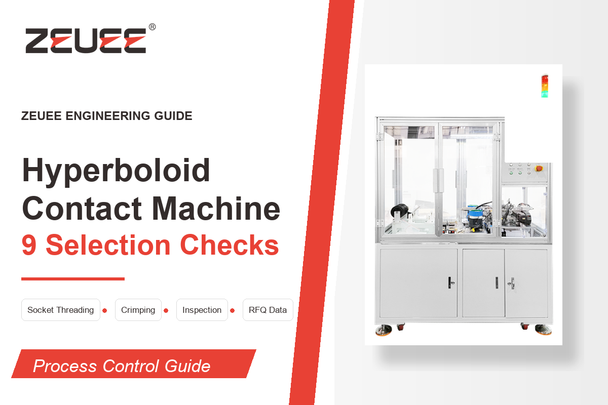
Don’t judge a hyperboloid contact machine on the contact name only. Look at its process window. We’re separating the contact technology from the equipment design decisions regarding socket threading, sleeve handling, rear-sleeve crimping, inspection and validation.
Quick answer: a hyperboloid contact machine is an automated device used to repeatedly perform selected manufacturing steps for a hyperboloid socket contact. These steps include contact-wire handling, socket or sleeve positioning, rear-sleeve crimping, force monitoring, and inspection. Reliability doesn’t come from the machine name alone; it comes from controlled, measured, and verified operations.
Most online search results related to this topic discuss the contact itself: history of hypertac, IEH and QA Technology product lines, smiths interconnect nomenclature, and general connector concepts. This is reasonable-buyers need to understand the distinct contact geometry before they can evaluate the equipment. A machine guide should do more; it should translate contact behavior into process checks that a manufacturing team can pass along to an automation vendor.
Google’s content cannibalization strategies also require that distinction. ZEUEE already offers a same-keyword solution page for product capability and quote requests. This article addresses the educational aspects: what the machine controls, the risks inherent in assembly, what evidence supports each assertion, and what information to include in a request for quotation.
What a Hyperboloid Contact Machine Actually Controls
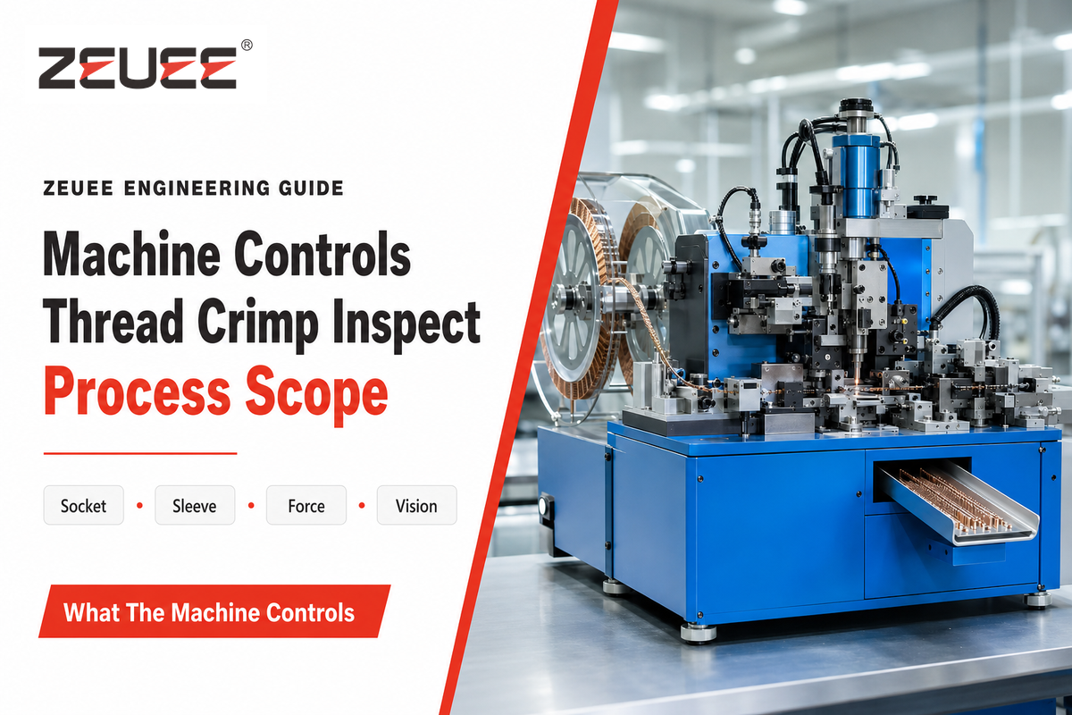
For this article’s purpose, a hyperboloid contact machine controls selected assembly processes around a hyperboloid contact design. For the machine type discussed here, the controlled operations include feeding small parts, orienting the contact or wire, threading the socket, locating the sleeve, crimping the rear sleeve, and conducting inspection and traceability tests.
Independent sources support hyperboloid contact behavior, connector standards context, and connector failure modes more directly than they support a universal rule for equipment purchasing. A more precise framing is that a well-defined machine can reduce process variation in a specific contact workflow. No machine specification can assure equal risk profiles for all contact families, AS39029 terminations, or connector applications.
SAE describes AS39029 as applying to removable crimp, solderless-wrap, and solder-type electrical contacts used in connectors and comparable components. This point is essential for accuracy: crimping is a significant element of many contact manufacturing discussions, but not the only termination type a buyer may encounter.
Scope: This guide focuses on socket threading, sleeve positioning, crimping or retention, and inspection within hyperboloid contact manufacturing. If your design specifies a solderless-wrap, solder-cup, PCB, bus-bar, or any other termination type, list that family as the first line item in your specification package.
Hyperboloid Contact Technology in One Working Model
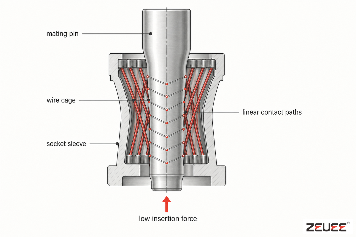
In a hyperboloid contact, angled contact wires inside a socket touch the mating pin along several linear contact paths. Sleeve design isn’t just aesthetic; it affects how the wire cage flexes around the pin, how the contact lines share load, and how insertion force is controlled.
Connector Supplier traces the technology to Francois Robert Bonhomme in 1956, originally for railway applications affected by shock and vibration. Tech Briefs describes the same working model in process terms: contact wires are angled with respect to the socket axis, forming a hyperboloid cage around the pin with several electrical paths.
This geometric configuration explains why this contact type is so often mentioned in high reliability interconnect applications. Trade sources associate hyperboloid contact technology with low insertion force, long mating cycles, lower contact resistance, and stable signal integrity in demanding environments. These are contact characteristics. Machine builders still have to show that feeding, threading, crimping, inspection, and recipe control keep the design inside its intended window.
The practical risk is assuming contact-brand language automatically defines the production line. A 0.3 mm pin target, a changed wire angle, or a sleeve datum shift can require a different fixture, inspection recipe, and factory acceptance test. If the vendor cannot show contact resistance and insertion-force records for the sample parts, treat the quote as incomplete.
“A change in wire angle, sleeve design or retention may give the part a new name but not the inherent behaviors.”
Contact terminology clarification: Smiths Interconnect and Hypertac documentation use brand-specific wording for hyperboloid contact technology in demanding environments where reliability and safety are essential. Treat that as source context for the contact family, not as a prescription that every buyer will replicate the exact contact design, wire arrangement, or acceptance plan.
One source phrase to treat carefully is “Hypertac hyperboloid is the original superior contact technology for use in demanding environments where reliability and safety are critical.” That wording is useful for contact-family context; it is not evidence that every hyperboloid contact machine, every contact system, or every assembly recipe achieves the same result.
For process review, translate connector design language into measurable inputs: number of contacts, number of wires, diameter of the wire, contact density, wire cage geometry, line of contact, points of contact on the surface of the pin, and retention of the contact after crimping. If the application requires high pin counts or small quantities of contacts for validation lots, ask how operators mate the contacts, engage the connector, and limit fretting wear without a lot of force.
For the contact itself, document whether the wire cage in a hyperboloid shape uses stamped or screw machine contacts, whether the inclination of the wire or a sharper wire angle changes insertion force, and whether qualification expects mating cycles without degradation under shock and vibration. Do not import medical connectors or medical equipment language unless that is your actual market.
Where Assembly Risk Enters the Process
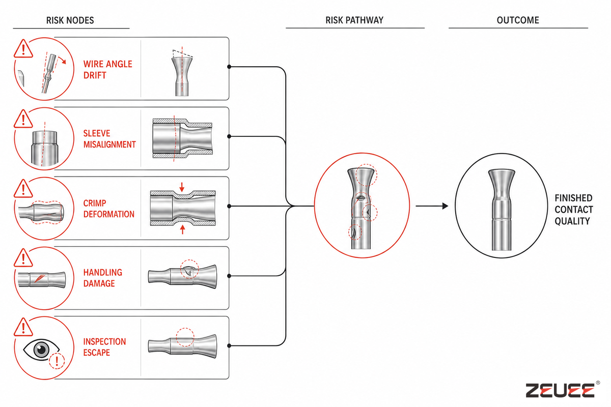
Risk enters at assembly time when a minute geometry shift has later consequences either electrical or mechanical. This includes factors such as pin diameter, wire gauge, the number of conductors, the form of the sleeve, the number of contacts per inch, the insertion path, the crimping force and how well the contacts are retained. An assembly can appear to be continuity-tested while internal damage later produces degradation, fluctuations in insertion force, or signal drops.
Google Patent US9490562B2 is useful because it addresses high-speed, automated manufacture of this type of contact and includes diverse terminations, angular contact wires, and processes including rolling, crimping, swaging, and permanently attaching the connections. The patent also references historical failures where contact wires pulled away from sleeves, though this doesn’t implicate ZEUEE machinery. That technical description shows why cycle counting isn’t enough for machine control.
NASA spacecraft connector process documentation adds several potential issues to the list: contamination, plating corrosion, insufficient retention, bent or sunk pins, failed crimps, wrong wiring, lost connections, damaged seals, handling damage, and production or application errors. A machine can address some risks, but only those embedded in the machine, tools, control system, and inspection methodology.
Failure Mode vs Machine Control Matrix
| Risk type | How it shows up | Machine control to request | Validation signal |
|---|---|---|---|
| Wire-angle drift | Changed contact lines around the pin | Guided threading path and tooling datum control | First-article sectioning or vision record |
| Sleeve deformation | Out-of-round socket or changed sleeve mouth | Supported nest, controlled press stroke, part-present check | Diameter gauge, optical inspection, sample log |
| Crimp under-compression | Low retention or unstable resistance | Force-displacement window and tool wear alarm | Pull test, retention test, force curve |
| Crimp over-compression | Barrel crack, wire damage, or contact distortion | Upper force limit, hard-stop review, reject chute | Microscope check and destructive sample review |
| Contamination | Open or intermittent contact after mating | Clean feeding path, air handling, part cover, operator handling rule | Visual criteria and resistance trend |
| Plating damage | Corrosion or fretting sensitivity | Soft-contact tooling surfaces and no-scratch transfer | Surface inspection and reject photos |
| Bent or recessed pin interface | Hard mating or unstable contact pressure | Coaxial loading, height sensor, pin-location fixture | Insertion-force and height data |
| Seal or coupling mismatch | Connector-level failure outside the contact cell | Downstream integration checkpoint | Assembly audit and customer application note |
| Mis-wiring or wrong contact family | Good-looking contact in the wrong cavity or workflow | Recipe lock, barcode scan, part-number gate | Trace record tied to drawing revision |
The Thread-Crimp-Inspect Control Map
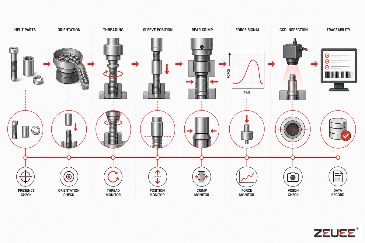
The shortest way to transform a contact design into machine concerns is with a Thread-Crimp-Inspect Control Map. This tool doesn’t presume a specific contact design. Rather, it raises questions concerning where the part is limited in its range of motion, how force is applied, and how it’s verified post-actuation.
| Process step | Main risk | Machine control | Inspection signal | Question to ask the supplier |
|---|---|---|---|---|
| 1. Incoming samples | Drawing and part revision mismatch | Part-number and drawing-revision setup | Approved sample set | How are sample lots tied to recipes? |
| 2. Wire or contact feeding | Small part jam, twist, or scratch | Bowl, tray, or magazine feed with sensor stop | Jam count per 1,000 parts | Which feed method was tested with our actual samples? |
| 3. Sleeve orientation | Wrong end presented to the tooling | Vision or mechanical orientation key | Orientation reject rate | Can the machine reject a reversed sleeve before crimping? |
| 4. Socket threading | Wire angle or path drift | Guided threading path and low-damage tooling | Optical check of wire path | What datum controls the wire path? |
| 5. Contact positioning | Off-axis load on the sleeve | Precision nest with part-present sensor | Position height and coaxiality check | What happens if the part is 0.05 mm out of position? |
| 6. Rear-sleeve crimping | Under-crimp or over-crimp | Force and displacement monitoring | Crimp curve and pull sample | Can the HMI store force windows by contact size? |
| 7. Retention check | Contact moves after assembly | Sample push or pull test station | Retention force record | Which contacts need destructive or sample testing? |
| 8. Visual inspection | Scratch, deformation, or missing feature | CCD or microscope-assisted inspection | Reject image library | Can accepted and rejected images be exported? |
| 9. Electrical check | Open, short, or unstable resistance | Continuity or contact-resistance test | Measured trend by lot | What resistance limit triggers automatic reject? |
| 10. Traceability | No record after field issue | Barcode, recipe, lot, and operator log | CSV or MES export | Can each reject be traced to lot, tool, and timestamp? |
NASA’s workmanship standard page says NASA-STD-8739.4 addresses interconnecting cable assemblies for electrical, electronic, or electromechanical devices. NASA’s update article also mentions pull-force values and crimp pull-test procedures. These sources aren’t a ready-made machine specification, but they support the point that settings, sample tests, and documented workmanship matter.
Machine Modules Behind a Stable Hyperboloid Contact Line
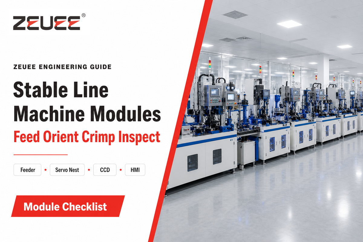
Stable contact lines often come from ordinary modules doing difficult work well. Feed the part without damage. Hold the socket without changing the shape. Apply force along a known axis. Inspect features that are too small for an operator to judge all day. Save a record that tells the quality team how the run performed.
If we were talking in the real factory, I would request a proof package module by module rather than glossy cycle-time claims. I would prefer a 4s module that works consistently to a 2s station with a hidden defect source. You would want sample results in pieces per minute, %reject, pull-force test curves, vision photos, and at least 30 parts made using the proposed method.
- Feed and orient: tray, bowl, magazine, manual load. Give us reason why this solution is used.
- Tooling and nest design:datum surfaces to hold the sleeve without damage. Don’t mark plating, or deform the mouth.
- Wire and threading setup:Guided path, to protect cage shape like a hyperbola.
- Crimp setup and process: Force – displacement curves, limits for recipe, sample tests, push/pull tests.
- Vision inspection:image capture of:sleeve damage, position of wires, deformities of mouth, absence of parts.
- Recipe and tracing: Locked setting by family, contact size, sleeve size, lot.
ZEUEE’s first-party About page states that Shenzhen Zeyu Intelligent Industrial Science Technology Co., Ltd was founded in 2005, completed a 20,000 square meter production base in Taihe, Jiangxi in 2020, and employs more than 120 specialists. It also lists ISO 9001:2015 certification, more than 150 patents, 0.005 mm machining accuracy, CCD inspection, four-axis robots, servo motors, and optoelectronic connector production for twisted-pin and wire-spring socket contacts. Based on that information, ask any potential supplier which capabilities are visible in the machine concept, sensor list, HMI screen, and sample parts.
Contact Families, M39029 Terms, and Standards Context
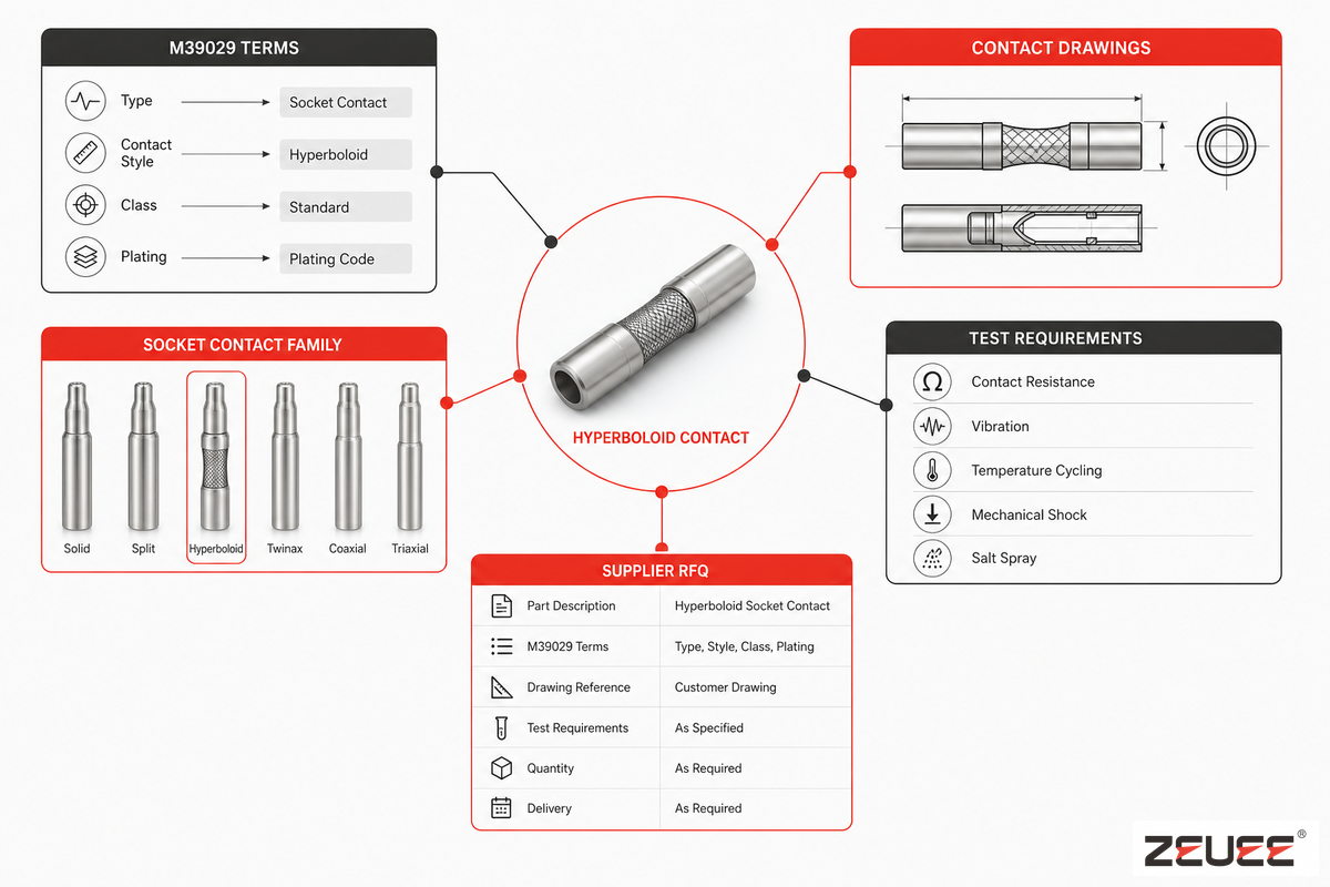
M39029 and AS39029 are commonly linked with socket contacts, crimp contacts, mil-aero connector families, and qualified contact lists. DLA’s QPD page lists SAE-AS39029 as the document governing QPL-AS39029 and shows a last update date of 05-MAY-2026. SAE’s page describes the scope as removable crimp, solderless-wrap, and solder-type electrical contacts.
From the perspective of machine purchasing, use the following three simple rules that derive from the standards information above.
The buyer risk is mislabeling a station as an “M39029 machine” because the contact family, factory process, and inspection burden are different. For a size 20 socket with 0.5 mm sleeve variation, the wrong request can create a fixture, crimp-window, or inspection problem before factory acceptance testing. If the supplier cannot map the drawing, ISO 9001 record, crimp stroke, and inspection evidence to your line, pause the request for quotation.
- Please don’t ask for a “M39029 machine” when your drawing specifies a certain contact family, size, sleeve, plating, contact, and method for inspecting parts.
- Please don’t mention a qualification status based on a brochure of a machine, as qualification refers to the part, process, materials, factory, and the procedure of approval, not the machine.
- Don’t blend contact design data with equipment data. Supplier knowledge can explain why a hyperboloid contact should work, but your factory must still prove your contact will repeatably perform on line.
One of the biggest blunders is to call and ask, “Can your machine do my contact?” A better request is: Size 20 socket contact, target sleeve outside diameter in mm, wire size and type, accepted crimp height or force range, drawing revision, sample quantity, inspection limit, and required traceability fields. With that detail, the machine supplier has testable data.
6-Point Contact Automation Readiness Matrix
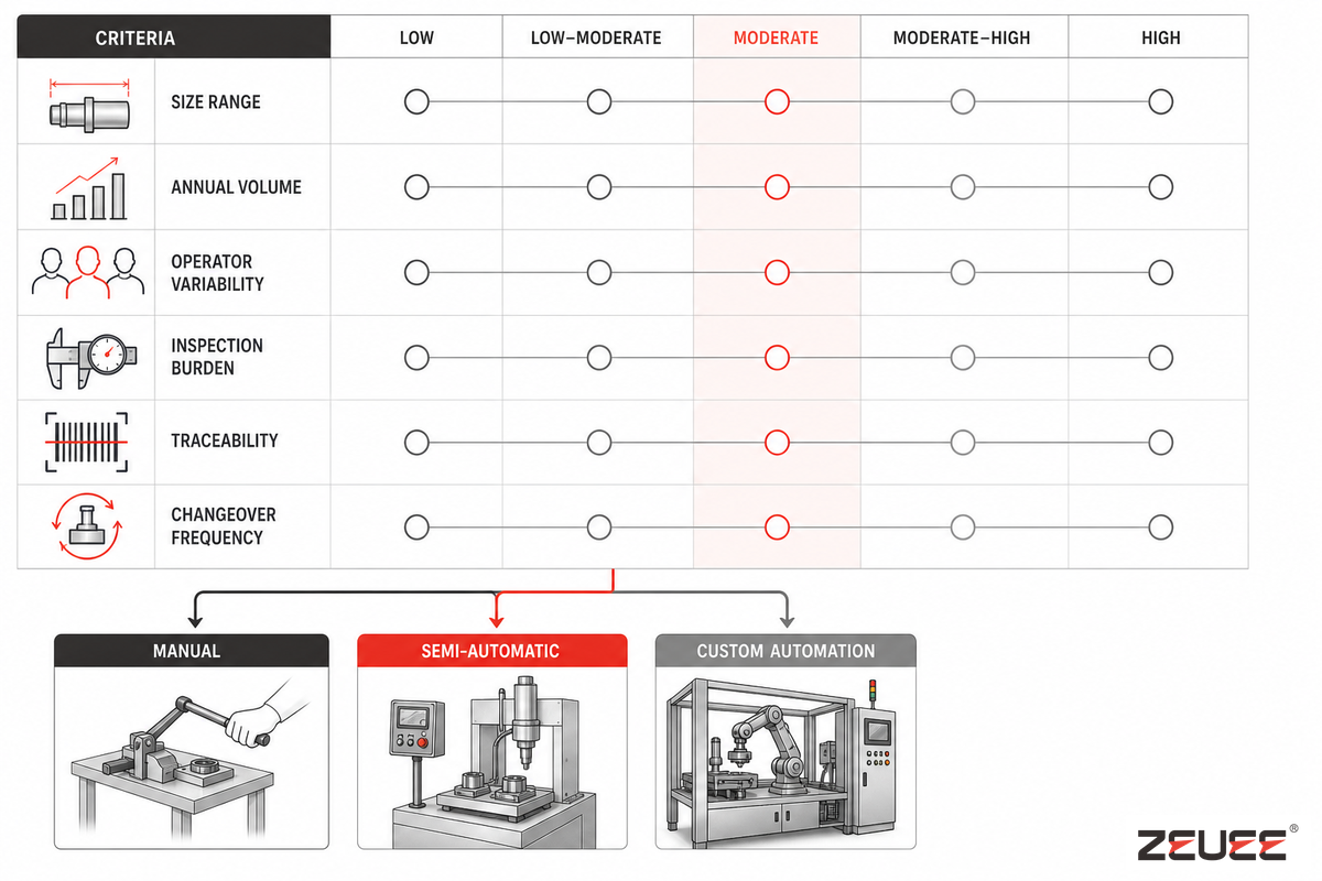
Use the 6-Point Contact Automation Readiness Matrix to separate projects that require a new custom line from those that can still be handled with a manual or semi-automatic setup. Treat it as a filter for engineering hours, not as a return-on-investment number.
| Readiness factor | Manual is acceptable | Semi-automatic may fit | Custom automation is worth scoping |
|---|---|---|---|
| 1. Contact size range | 1 stable size, low mix | 2-3 nearby sizes with simple tooling | 4+ sizes or very small geometry needing recipe control |
| 2. Annual volume | Prototype or repair lots | Small batches with repeat orders | High-volume lots where measurable reject drift costs real money |
| 3. Operator variability | Experienced operator, easy visual control | Operator loads, machine controls force | Skill-dependent threading, alignment, or crimp result |
| 4. Inspection burden | Simple go/no-go check | Sample checks plus manual microscope review | CCD, force curve, resistance, or retention data per lot |
| 5. Traceability requirement | No customer record beyond batch release | Lot-level records | Part, station, operator, recipe, and timestamp records |
| 6. Changeover frequency | Rare changeover | Weekly changeover with fixtures | Daily changeover needing HMI recipes and poka-yoke checks |
You don’t need all 6 of the factors on the right side to justify the investment. Typically, three factors are enough: the risk of poor repeatability, the burden of manual inspection, and pressure from customers for traceable data. Add to that factors like contact density or low insertion force targets, and the conversation shifts from “can we automate?” to “what evidence will the first article and the full acceptance sample run provide?”
Quality Checks Before You Approve a Hyperboloid Contact Machine
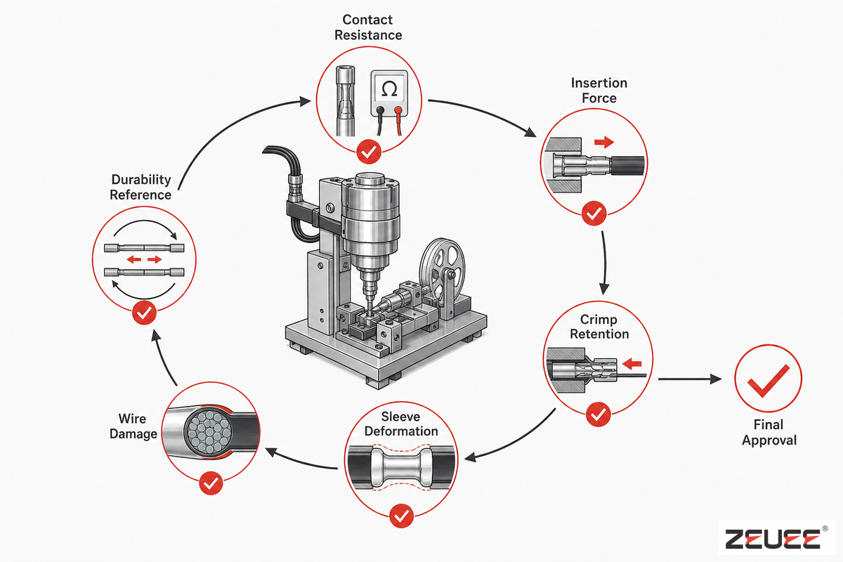
Don’t buy an automation system based solely on cycle time. Buy the process capability window. Every contact assembly line should demonstrate its ability to control critical features before production begins, as part of the first article approval process, and after initial tool wear begins to manifest itself.
NASA NTRS connector evidence is blunt on this subject: connector failure modes can include contact-retention problems, plating defects, connector coupling wear, bent pins, cracked crimp barrels, failed seals, handling damage, dimensionally incorrect parts, and customer misapplication. A hyperboloid contact machine may control some of these conditions; the acceptance plan must state what’s in scope and what’s out of scope.
Measurement Pack for Supplier Trials
Use the following fields as a trial-data template, not as universal acceptance limits. Replace every example value with the drawing, sample, or factory value for your contact. In this stage, the shape of the contact sleeve should be recorded as a datum because sleeve geometry sets wire-cage support and crimp access.
| Field | Record the buyer’s actual value | Why the number matters |
|---|---|---|
| Pin diameter | Use drawing values such as 0.3 mm, 0.5 mm, or 1.0 mm only when they match the part file. | Sets nest datum and mating-pin clearance. |
| Sleeve dimensions | Record inside diameter, outside diameter, and length in mm; add 0.01 mm resolution only if the gauge supports it. | Controls support, mouth condition, and crimp access. |
| Wire diameter | List wire diameter in mm and tolerance in mm; use a 0.02 mm example only as a format cue. | Changes wire-cage stiffness and contact-line behavior. |
| Crimp stroke | Capture press position in mm and stroke repeatability in mm from trial data. | Connects tooling motion to rear-sleeve compression. |
| Cycle time | Show proven average in sec, not only a target; a 2 sec claim and a 4 sec trial result mean different risks. | Separates capacity promise from stable output. |
| Inspection interval | State review timing such as every 4 hours when tool wear is visible in the sample run. | Prevents late drift after first-article approval. |
| Reject percentage | Report trial rejects as %, for example 2% or 5%, only with sample count and reject reason. | Turns good-looking samples into process evidence. |
| Electrical screen | If the contact requires it, record real test values such as 5 V, 1 A, 10 MHz, or 1 GHz. | Links machine output to contact-resistance or signal checks. |
| Factory utilities | Use plant standards such as 0.4 MPa or 0.8 MPa air, 220 V power, 24 V sensor supply, 48 V control power, and 8 hours shift length only when they match the installation site. | Avoids a good station failing during integration. |
Recommended approval checks
- Contact Resistance – Measure and use an acceptable force range rather than a simple continuity check.
- insertion and Withdrawal Force – Compare measured forces for samples of the contact by size and pin diameter.
- Retention Force – Where the contact design permits, perform pull tests on the samples.
- Crimp Section Review – Inspect the sample contact crimp for under or over-compression and damage to the wire.
- Sleeve Geometry – Measure for dimensional accuracy and damage such as deformed opening, changes in diameter, and deviation from coaxiality.
- Vision Inspection – Capture both accepted and rejected sample images and include in the acceptance documentation rather than just providing the number of good and bad contacts.
- Recipe Security – Provide secure recipes with logging of operator name, lot number, and timestamp for any recipe changes.
- Tool-Wear Inspection – Specify the interval at which the critical tooling components will be inspected (e.g. every 4 hours or every 5,000 contacts).
- Customer Application Boundaries – Specify the parameters of the application which the automation cell won’t control (e.g. final connector seal application, cable routing strain).
Approval Rules – The cycle time of the line reflects capacity; process capability is quality. Acceptance of the equipment must consider sample size, reject criteria, crimp force or displacement, contact resistance measurements, and retention/withdrawal tests as applicable to the contact design.
9-Row Specification Checklist to Send a Machine Builder
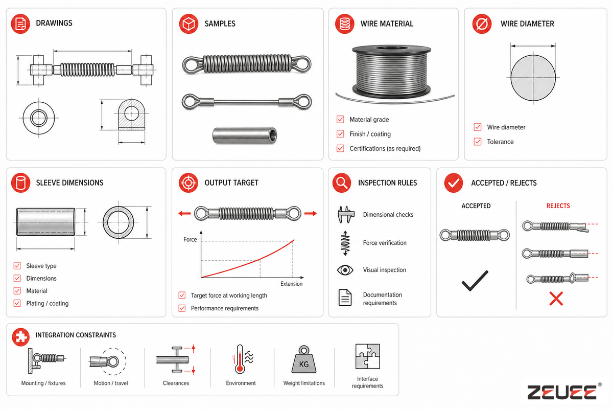
Use the 9-Row Hyperboloid Contact Machine Specification Checklist as the necessary bridge. It guides the vendor before they present price, delivery time, or layout information, reducing guesswork and avoiding generic contact-assembly language in a proposal.
| Specification category | What to send | Why it matters | Missing-data risk |
|---|---|---|---|
| 1. Contact drawing | PDF and native drawing, revision, tolerances | Defines tooling datum and inspection points | Wrong nest or wrong sleeve support |
| 2. Physical samples | At least 30 good samples and 10 known rejects if available | Lets the builder test feed, grip, and inspection rules | Proposal based on theory only |
| 3. Wire material | Alloy, plating, hardness, handling limits | Controls scratch risk and forming response | Damaged contact wires |
| 4. Wire diameter | Nominal value, tolerance in mm, supplier variation | Affects wire cage behavior and contact area | Unstable contact lines |
| 5. Sleeve dimensions | Inside and outside diameter, length, mouth condition | Sets support and crimp tooling design | Deformation or off-axis load |
| 6. Target output | Parts per hour, shift pattern, planned lot size | Balances automation level and feeder complexity | Overbuilt or underbuilt equipment |
| 7. Inspection rules | Vision, force, contact resistance, retention, sample test plan | Turns quality into pass/fail data | Good-looking defects escape |
| 8. Accepted rejects | Photos and measurements for scratch, crack, bent wire, bad crimp | Trains vision and operator decisions | Supplier and buyer judge defects differently |
| 9. Integration constraints | Power, air, footprint, MES, barcode, upstream/downstream process | Prevents a good cell from failing on the production floor | Late redesign, extra guarding, or data-gap issues |
Once you’ve drafted the checklist, review the hyperboloid contact machine solution from ZEUEE. That’s the product/quote landing page; this page is the engineering prep.
When to Move From Manual Work to a Custom Hyperboloid Contact Machine

Turn to custom automation when variability arises from process rather than individual performance. Small-volume contact production may rely on a skilled operator, jig, and a microscope. However, in high-volume work, those steps can generate hidden variation if parts are small and contacts are tightly packed; an application can demand a pin diameter no smaller than 0.3 mm, with no space for damage from visual handling.
Here’s a simple way to decide: if contacts are easily handled, lots are small, and acceptance testing is light, start by improving your jig. If your contacts have lots of pins, strict insertion force targets, need high retention, and demand detailed traceability, investigate a semi-automatic system. If you need to control feeding, threading, crimping force, inspection, and records to maintain quality standards, a custom machine warrants formal design review.
The trap is automating before measuring the source of variation. If a 2 sec target produces 5% rejects while a 4 sec trial produces stable parts, the factory problem is not speed; it is process capability. Ask the supplier to show the fixture datum, inspection record, and sample-run data before converting a manual jig into a custom station.
As market context, these pressures exist, but they aren’t proof for this specific machine. Mordor Intelligence forecasts aerospace and defense connectors growing from USD 4.33 billion in 2026 to USD 5.55 billion in 2031, a 5.13% compound annual growth rate. Wevolver’s 2025 connector trends article cites miniaturization, ruggedness, high current density, advanced materials, and digital sourcing as broad connector pressures. None of those trends alone explain demand for a particular machine. Instead, they explain why buyers ask for stronger proof from contact-production equipment.
Ready to Review Your Contact Process?
ZEUEE can assess drawings, samples, sleeve dimensions, output expectations, inspection needs, and integration constraints before a scope-design review. Bring the 9-row checklist and define the acceptance test procedure before asking for a machine concept. The goal is to decide which process controls, fixture datums, inspection records, and sample-run evidence must be visible before quotation.
A late request-for-quotation mistake can delay tooling or factory acceptance testing when the sample pack omits a 0.5 mm sleeve range, drawing revision, or inspection method. Send drawings, sample parts, and acceptance data before asking ZEUEE for a custom machine concept.
FAQ
What is a hyperboloid contact machine?
View Answer
The machine assembles or finishes hyperboloid socket contacts through controlled feeding, positioning, sleeve handling, crimping, retention, and inspection. Its value is the repeatable process window: fixture datum, force limit, sample test, trace record, and acceptance evidence tied to the specific approved contact drawing and production lot before release to manufacturing.
Is a hyperboloid contact machine the same as a hyperboloid contact?
View Answer
No. Contacts are connector components-often hyperboloid socket elements with an array of angled wires to make electrical connections. The machine is a system to produce or finalize them. This distinction is important: the contact design describes the product; the machine design describes the method. The latter’s acceptance criteria must prove its control of process elements such as feeding, tooling, forces, inspection, traceability, and part-specific reject handling before it earns production approval on your floor with documented samples and limits.
What information should I prepare before requesting a custom hyperboloid contact machine?
View Answer
Prepare drawings, revision level, samples, contact-size range, wire material, sleeve dimensions, target output, defect examples, inspection rules, and integration constraints. Add known limits for crimp force, contact resistance, insertion force, withdrawal force, retention, recipe control, barcode records, image storage, acceptance sample quantity, and factory test conditions when available before quotation.
Can one machine process different contact sizes?
View Answer
Yes, if the size matrix is engineered into the feeder, tooling, sleeve support, recipe control, and inspection plan. Ask whether each size keeps the same datum logic, force window, traceability fields, and reject rules; otherwise changeover turns one machine into several unproven setups.
Why is inspection so important in hyperboloid contact assembly?
View Answer
Inspection matters because hyperboloid contacts rely on small geometry, stable wire position, sleeve condition, crimp compression, and retention. A continuity check can miss scratches, sleeve deformation, wire-angle drift, weak retention, or plating damage. Pair image checks with force or displacement curves, contact-resistance checks, sample pull tests when allowed, reject photos, and lot records so the buyer sees the defect controls, not only the final pass count. That evidence supports acceptance after tool wear begins and during later process changes.
References
- NASA-STD-8739.4 Workmanship Standard for Crimping and Wiring
- NASA SMA update on NASA-STD-8739.4A
- NASA NTRS: Spacecraft Electrical Connector Selection and Application Processes
- SAE Mobilus: AS39029 Contacts, Electrical Connector, General Specification For
- DLA QPD Search: QPL-AS39029
- Google Patents: US9490562B2 Reduced diameter hyperboloid electrical contact
- Connector Supplier: What’s Hyperboloid Contact Technology?
- Connector Supplier: Hyperboloid Contact Technology is Still Going Strong
- Tech Briefs: Hyperboloid Wire Basket Connector Technology
- Wevolver: Connector Trends 2025
- Mordor Intelligence: Aerospace and Defense Connectors Market
WHY WE WRITE THIS
About ZEUEE Engineering Insights
ZEUEE shares technical guides based on real automation project experience. Since 2005, we have designed and manufactured non-standard automation equipment for connector assembly, wire harness production, robotic lines, vision inspection, and smart factory upgrades.
Founded in 2005
20,000 m² production base
120+ specialists
150+ R&D patents
ISO9001:2015 certified