Get in touch with Zeyu lntelligent Industrial Company

Micro Twist Pin Machine: Contact Physics, Tolerance Control, and Line Sizing

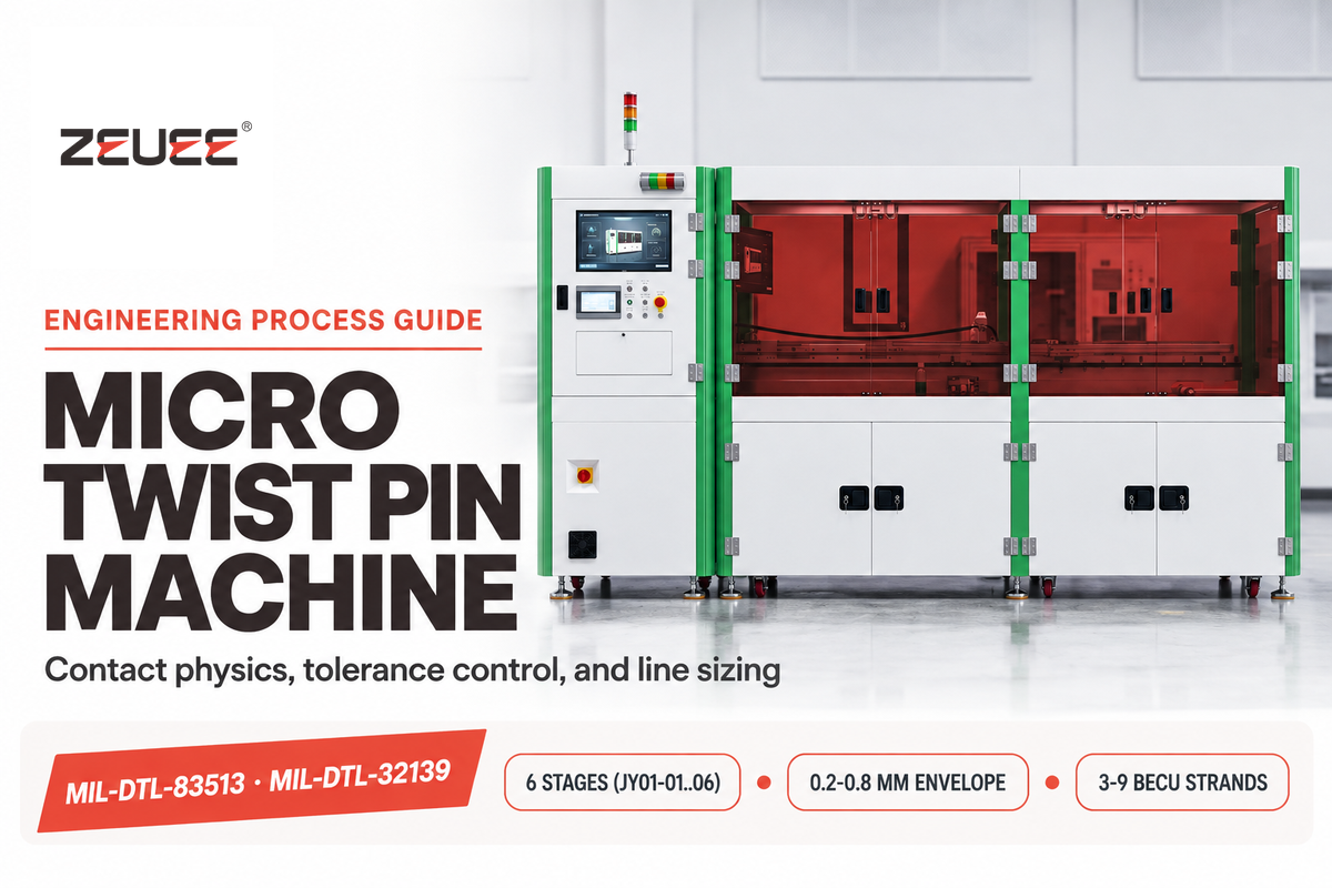
A Micro Twist Pin Machine manufactures miniature helical beryllium-copper contact bundles for aerospace, defense, medical, and downhole connectors. This machine doesn’t press straight solid circuit board headers. Across an automated assembly line, this system strands fine alloy wires, laser welds both ends, forms a spring bulge, and terminates sleeves.
Updated November 2026 · Engineering Process Reference
Quick Specs
| Governing Connector Standards | MIL-DTL-83513H Amend 2 (0.050 in / 1.27 mm) and MIL-DTL-32139B (.025 in / 0.64 mm) |
| Typical Wire Architecture | 7-wire BeCu bundle (or 7 outer spring strands around a 3-wire copper core); ZEUEE cells cover 3–9 strands (0.2 to 0.8 mm envelope) |
| Core Mechanical Limits | Max 10 oz mating force per contact; min 5 lb retention; min 500 cycles (MIL-DTL-83513) |
| Electrical & Dynamic Ceiling | 28 mΩ (SAE AS22759/11) or 32 mΩ (SAE AS22759/33) max LLCR on 26 AWG Size 24 stranded wire; 25 mΩ solid (Table VI); ≤ 1 µs break |
| Modular Line Architecture | 6 stages: JY01-01 stranding, JY01-02 straightening, JY01-03 cut/weld, JY01-04 bulging, JY01-05 housing crimp, JY01-06 wire crimp |
Automated production of micro twist pins uses sub-millimeter bulge concentricity throughout stranding, laser tip welding, waist-drumming, and four-point crimping. Closed-loop inline CCD inspection checks dimensional tolerances, and destructive pull tests verify weld and crimp strength, before assembled connectors undergo separate MIL-DTL-83513 and MIL-DTL-32139 QPL qualification testing. Tight millisecond laser pulses protect the heat-affected zone in C17200 alloy.
What a Micro Twist Pin Machine Actually Makes
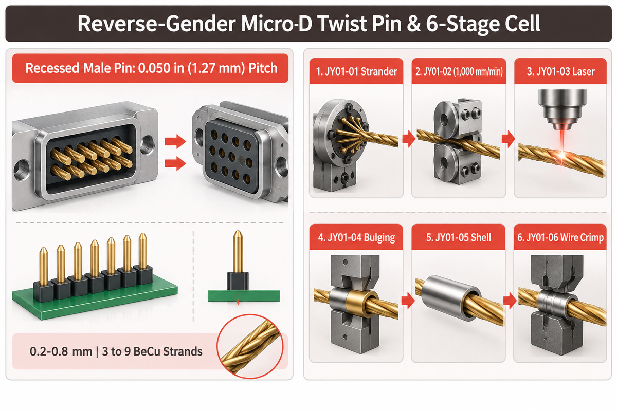
A twist pin machine twists a seven-wire beryllium-copper (BeCu) bundle, or seven outer spring strands wrapped around a three-wire copper wire core, to produce contacts for 0.050 in (1.27 mm) Micro-D connectors. ZEUEE’s commercial product page documents a 6-station architecture (JY01-01 to JY01-06; 0.2-0.8 mm across 3–9 strands of beryllium-copper). Buyers can inspect module specs directly on ZEUEE’s automated micro twist pin machine line page.
ConnectorSupplier’s MIL-DTL-83513 guide describes how twist pin contacts are manufactured by welding seven spring wires together. Once manufactured, the pin mates into a socket so the outer wires bow radially against the socket bore under axial compression. Multi-line contact wiping sustains low resistance even under dynamic aerospace loading.
MIL-DTL-83513 also reverses housing recess geometry compared to conventional 2.77 mm D-subminiature connectors. However, the compliant male twist pin is recessed in the pin insulator for physical protection. The rigid tubular female socket extends beyond the insulator wall.
Buyers must also differentiate between male twist pins and true hyperboloid sockets before finalizing an equipment specification. ConnectorSupplier defines hyperboloid contact technology as a female sleeve holding a skewed basket of wire around a solid male pin. In micro and nano connectors (Micro-D and Nano-D), the multi-wire spring element is part of the male pin. Suppliers of automation equipment may group both of these spring structures together under hyperboloid.
Contact Production Line vs PCB Press-Fit Pin Insertion Machine
| Equipment Category | Feedstock & Alloy Class | Primary Forming Model | Resulting Component Type |
|---|---|---|---|
| 1. Integrated Six-Machine Twist Pin Cell | 0.2 mm to 0.8 mm bundle envelope (3–9 BeCu strands) | Continuous stranding, welding, bulging, and sleeve crimping | MIL-DTL-83513 / 32139 recessed male pins |
| 2. Helical Wire Strander (JY01-01 Category) | BeCu outer spring coils + central copper core wire(s) | Multi-spool magnetic tension payoff and lay twist | Wound continuous helical blank reels |
| 3. Stress-Relief Straightener (JY01-02 Type) | Continuous coiled C17200 strand blanks | Inline tension flattening up to 1,000 mm/min (ZEUEE JY01-02 spec) | Cast-neutralized straight pin blanks |
| 4. Dual-End Laser Cut & Welder (JY01-03 Model) | 0.2 mm to 0.8 mm sheared twist-pin blanks | Carbide shear + inert-gas-shielded dual-end ball weld | Sealed tip-welded pin sub-blanks |
| 5. Servo Waist-Drumming Machine (JY01-04 Type) | 0.2 mm to 0.8 mm welded bundles (vs. 0.0016, 0.0033, 0.0050 in patent coils) | Closed-loop anti-helical servo jaw clamp (270-degree stroke in US6584677B2) | Spring-bulged male twist pin contact |
| 6. Housing Pin Inserter & Crimper (JY01-05 Category) | Formed BeCu spring pins & insulator shells | Robotic seating + coaxial CCD posture check | Shell-retained connector pin arrays |
| 7. Lead Wire Strip & Crimp Unit (JY01-06 Class) | Stranded hookup wire + sleeve barrels | Wire stripping + SAE AS22520 four-point indent crimp | Terminated wire-lead assemblies |
| 8. PCB Solid Pin Inserter (Through-Hole Type) | Rigid brass or phosphor-bronze header wire | Cut & vertical mechanical press-fit into board vias | Through-hole circuit board pins |
| 9. Pneumatic Cassette Vision Sorter (Sorting Class) | Formed BeCu twist pins (0.0077 g 4-bulge pin in US6584677B2) | Air-tube transfer + multi-angle CCD posture screening | Oriented pass/fail magazine cassettes |
Mixing up solid PCB pin insertion systems with twist-pin machinery disrupts line automation budgets early. Commercial press-fit PCB inserters can place rigid square pin headers into plated printed circuit boards. Those units never strand wire, fuse tip domes, or form elastic bulges. The first process in contact production is creating the helical spring. Only then can automatic pin insertion machines seat the contact in the connector shell.
How does a micro twist pin machine work in MIL-DTL-83513 manufacturing?
A twist-pin manufacturing cell works sequentially across six specialized stations rather than a single stamping press. First, a multi-spool strander (JY01-01) twists outer BeCu spring strands around copper core wire(s), scaling across 3 to 9 strands on ZEUEE systems. Second, on ZEUEE’s JY01-02 unit, an inline straightener pulls coil memory flat at up to 1,000 mm/min before shearing blanks.
Third, dual-end laser welding (JY01-03) melts both cut tips and forms them to smooth ball shapes in an inert shielding gas atmosphere. Fourth, a servo waist-drumming module (JY01-04) clamps two axial collars and rotates one end anti-helically to form the bulge. Fifth, a four-axis housing inserter and crimper (JY01-05) seats contacts into connector shells under vision checks. Sixth, a robotic terminal crimping unit (JY01-06) strips lead wire and applies four-point indent crimps under CCD inspection.
MIL-DTL-83513 and MIL-DTL-32139 Standards Governing Pin Geometry
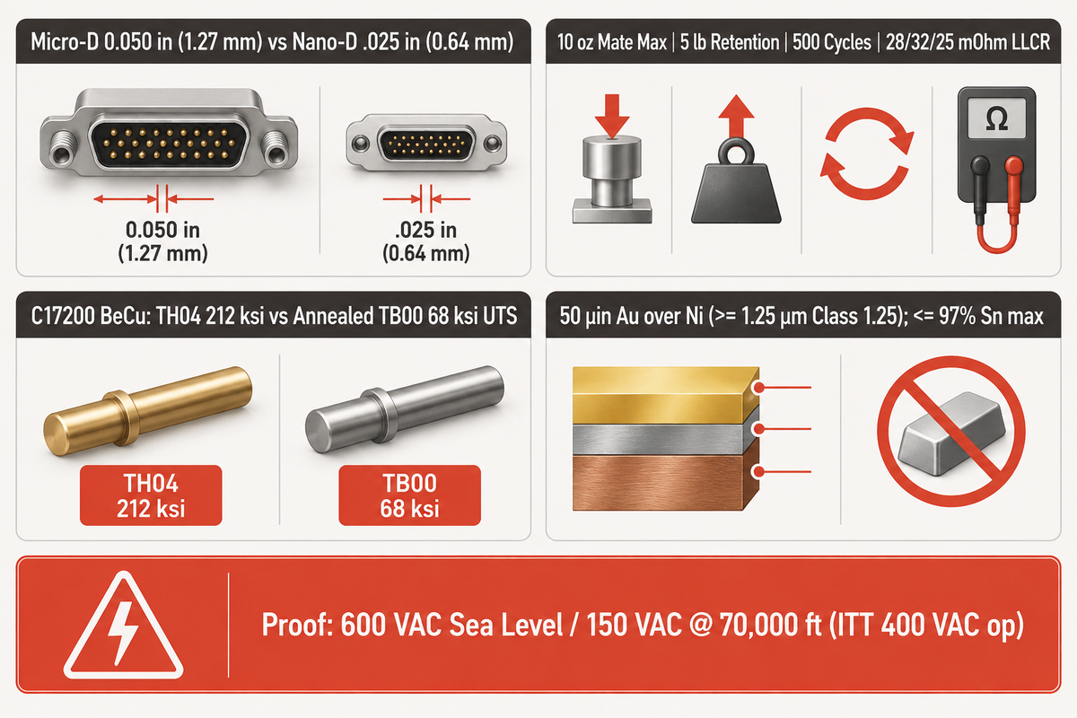
Two active DLA defense documents define exact contact pitches and mechanical limits for automated lines. MIL-DTL-83513 Revision H Amendment 2 governs 0.050 in (1.27 mm) Micro-D contacts at 10 oz max mating force. It also enforces a 5-pound minimum axial retention floor. Meanwhile, MIL-DTL-32139 Revision B Amendment 3 halves center pitch to .025 in (0.64 mm) for Nano-D connectors.
Checking wire dimensions without qualification context leads to failed QPL audits. Under MIL-DTL-83513H documented in Military Embedded’s engineering guide, Size 24 contacts span eight layouts from 9 to 100 pins. Qualified contacts must survive 500 durability mating cycles, and the connectors are rated for -55 °C to +125 °C operation. Under vibration, continuity can’t break for more than 1 microsecond at 100 mA test current. MIL-DTL-83513H Table VI caps Size 24 contact LLCR at 28 mΩ on 26 AWG SAE AS22759/11 stranded leads, 32 mΩ on SAE AS22759/33 stranded leads, and 25 mΩ on 24–25 AWG solid leads.
BeCu Wire Alloy and Machine Engineering Tools Calibration
Wrought beryllium copper C17200 supplies the elastic modulus needed across these thermal cycles. In the Copper Development Association C17200 datasheet, this alloy carries 1.80–2.00% beryllium and 22% IACS conductivity at 68 °F. Age-hardened TH04 wire reaches 212 ksi typical tensile strength and 195 ksi yield strength. By contrast, annealed TB00 wire falls to 68 ksi UTS and 28 ksi yield strength. Uncontrolled welding heat softens the spring bulge and degrades contact retention.
Surface finishing creates two common specification errors in mil-spec connector procurement. As ConnectorSupplier reports on MIL-DTL-83513 material caps, pure tin exceeding 97% tin by mass is prohibited. Conformal coatings can’t stop tin whiskers across narrow 0.64 mm clearances. At least 3 percent lead alloying is mandatory in any tin-based finish.
Second, confusion about plating thickness across military and commercial standards is common. Valence Surface Technologies explains on ASTM B488 that each class states an absolute minimum thickness floor. Values are not batch averages across plated barrels. Below Class 5.0 (5.0 µm / ~200 µin), ASTM requires nickel underplating over copper substrates. Note that ASTM Class 1.0 (1.0 µm) sits thinner than MIL-DTL-45204 Type II Class 1 (~50 µin / 1.27 µm).
| Engineering Parameter | Micro-D (MIL-DTL-83513H) | Nano-D (MIL-DTL-32139B) | Standard D-Sub Baseline |
|---|---|---|---|
| Contact Center Pitch | 0.050 in (1.27 mm) | .025 in (0.64 mm) | 0.109 in (2.77 mm typical) |
| Typical Pin Count Layouts | 9, 15, 21, 25, 31, 37, 51, 100 pin | 9–51 positions (miniature) | 9–50+ dual-row shells |
| Mating Force Ceiling | ≤ 10 oz per contact; ≥ 0.5 oz min hold | Lower size-scaled threshold | Solid pin/socket sliding fit |
| Contact Retention Floor | ≥ 5-pound axial load | Per QPL insert geometry | Standard clip retention |
| Durability Cycle Floor | 500 mating cycles min | Per slash-sheet durability | Commercial grade sliding cycles |
| Contact Resistance Spec | 28 mΩ (SAE AS22759/11) or 32 mΩ (26 AWG, SAE AS22759/33) max LLCR on Size 24 leads; 25 mΩ solid (Table VI) | Size-scaled EIA-364-23 limit | Application-rated current drop |
| Operating Temperature | -55 °C to +125 °C standard | Up to +200 °C specialty grades | Rated by insulator polymer |
| Gold Plating Standard | MIL-DTL-45204 Type II Class 1 (~50 µin Au / Ni; no Ag) | ASTM B488 Type II Class 1.25 / Ni | Commercial flash Au finishes |
| Pure Tin Limit | ≤ 97% Sn max (≥ 3 percent Pb required) | Whisker-free alloy finish | Matte or bright tin allowed |
Qualification Voltage Boundary: MIL-DTL-83513 lists 600 VAC at sea level and 150 VAC at 70,000 ft altitude as short-duration proof tests. These values aren’t continuous operating voltage limits. Separately, Military Embedded notes that ITT specifies a 400 VAC operating rating on its commercial MDM PCB family distinct from withstand tests. Engineered creepage and clearance spacing around 0.050 in (1.27 mm) Micro-D pitches must stay conservative against those sea-level and 70,000 ft test boundaries.
How Stranding, Laser Welding, and Waist-Drumming Stack Up
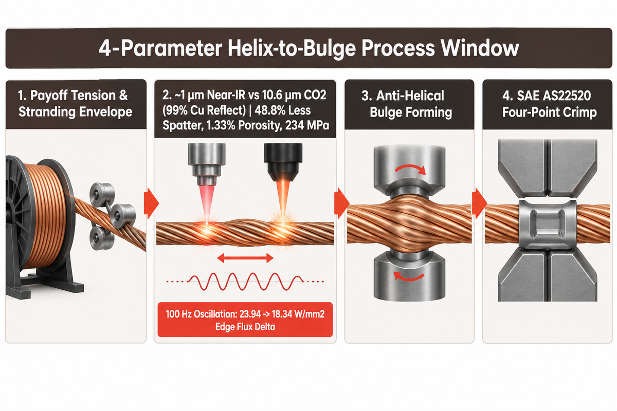
Contact spring force and bulge symmetry build up across four serial stations, not at the waist-drumming press alone. Wire payoff tension, thermal straightening, dual-end tip fusion, and servo waist-drumming all alter finished geometry. Treating any station as an isolated box hides the root physical cause of final assembly rejects.
Twist pins fail when the helical strands slip unevenly or lose temper in a wide heat zone. The early connector design in IBM patent US3258736A wound outer coils around a central core with lightly swaged ends cut off after board insertion. By contrast, a modern helical bundle wraps gold-plated beryllium-copper outer strands over a central core and joins at both ends. Axial compression pushes those wires outward to become parallel leaf springs.
Modern forming cells replace uneven hand twisting with synchronized motion control. For stacked-PCB z-axis pins, Medallion Tech patent US6584677B2 details forming fine coils sized around 0.0016, 0.0033, and 0.0050 in. Two spaced jaws grip a wire bundle and rotate anti-helically over a continuous 270-degree stroke. Positive grip limits torsional slip and holds four-bulge intervals within 0.002 in tolerances.
In Medallion Tech’s US6584677B2 four-bulge example, completed pins weigh roughly 0.0077 grams each. Dropping bins tangle the lightweight springs, causing them to form knots that deflect contact tips. The pneumatic cassette sorting system used to sort completed pins eliminates collisions by moving pins into indexed guide channels.
Because pure copper reflects roughly 99% of 10.6 µm CO2 laser energy, twist-pin tip fusion relies on near-infrared (~1 µm) pulsed Nd:YAG or fiber lasers. Even at near-infrared wavelengths, copper reflectivity and thermal conductivity demand controlled beam dynamics to stabilize the melt pool. A 2023 ScienceDirect copper welding study compared circular “O”-shaped oscillation scanning against straight linear spots on 1.5 mm copper. Circular trajectories reduced spatter by 48.8% and dropped internal porosity to 1.33% (38% of linear welds). Welded joints still retained 234 MPa tensile strength, reaching 97.5% of base metal performance.
Beam wobble amplitude also has strict thermal limits that processing teams cannot exceed. A September 2026 review in the Journal of Materials Processing Technology confirms that higher amplitude isn’t always optimal. Although 100 Hz beam oscillation lowered edge-to-center flux delta from 23.94 W/mm2 to 18.34 W/mm2, excess amplitude reduces penetration depth. Oversized wobble also leaves dwell heat at the beam turn-around point and promotes edge cracking.
Metallurgy tests help us understand the importance of short pulse durations for C17200 alloy springs. One pulsed Nd:YAG study on annealed 0.2 mm Cu-Be sheet examined weld strength drops alongside prior aging behavior. Specifically quoting Zalkind and Moreno (1999) on C17200 electron-beam welds, post-weld aging hardens the HAZ significantly while incoherent CuBe precipitation keeps the fusion zone from gaining comparable hardness. Millisecond pulses help keep the heat affected zone narrow. Without short pulses, the Cu-Be alloy welds suffer HAZ brittleness, loss of elasticity, and diminished spring strength.
4-Parameter Helix-to-Bulge Process Window
The 4-Parameter Helix-to-Bulge Process Window below relates each upstream parameter to its downstream contact failure risk.
| Process Parameter | Primary Control Mechanism | Upstream Dependency | Downstream Failure Risk |
|---|---|---|---|
| 1. Strand Payoff Tension & Pitch | Per-head magnetic tensioner + inline laser OD gauge | Raw spool coil cast memory & wire surface cleanliness | Unequal strand length bows bulge off-axis during drumming |
| 2. Stress Relief & Shear Cut | Matched carbide collet bushings (up to 1,000 mm/min straightener) | Consistent helical lay pitch from the stranding stage | Shear burr or flared strand tip blocks weld dome symmetry |
| 3. Dual-End Laser Fusion Pulse | Inert shielding gas flow + tuned oscillation frequency/pulse ms | Tight strand contact fit-up at shear face without oil | Wide HAZ softens C17200 spring elasticity; oversized weld ball jams sleeve |
| 4. Servo Waist-Drumming & Crimp | 270-degree anti-helical servo clamp + SAE AS22520 4-point crimp | Centered end welds able to carry compressive bulging torque | Collapsed arch drops separation force under 0.5 oz floor; broken tip |
Process case – BeCu weld embrittlement and HAZ mismatch: Mousavi and Niknejad (2010) reported lower tensile strength in pulsed welds on as-annealed 0.2 mm UNS C17200 sheet than in the base metal. Tensile strength of the weld metal fell below the as-annealed base alloy since the CuBe phase precipitates during solidification. Heat Affected Zone (HAZ) grain boundaries next to the molten nugget liquefied. For electron-beam C17200 welds cited from Zalkind and Moreno (1999), post-weld aging raised HAZ hardness sharply above the weld metal. This created a fracture plane through the weld metal. Miniature twist pins require narrow pulse control and precision wire stress relief before forming to prevent cracked domes during bulging.
After twist pin assembly and bulging, sleeve locking follows SAE AS22520 four-point indent geometry. Uniform blank lengths keep sleeves aligned inside precision crimp jaws. Engineers can review dual-end laser fusion setups in our twist pin cutting and laser welding guide.
Twist Pin vs Stamped, Machined, and Pogo Contacts
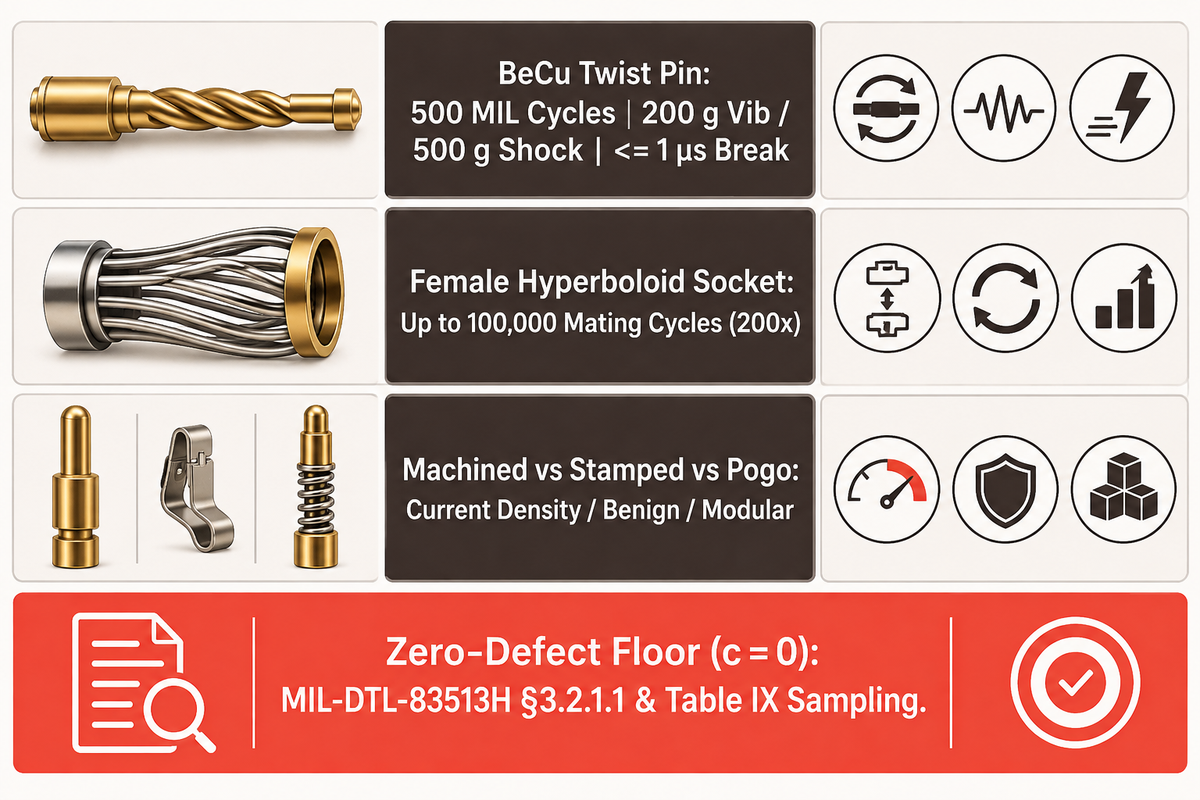
Contact geometries that work best in 0.64-1.27 mm aerospace connectors exposed to high shock and vibration are helical beryllium-copper twist pins, which provide better continuity than stamped, machined or pogo contacts, but don’t necessarily lead to improved cycle life. It’s necessary to decouple the selection of contact geometries from the economics of factory automation. Contact-geometry selection balances 500 to 100,000 mating-cycle targets and vibration thresholds, whereas automation budgets center on passing MIL-DTL-83513H c = 0 audits without manual rework.
Two poor rules influence vendor evaluations online. The first is assuming more contact points win over lower pin designs. The second is claiming shops must produce five million contacts a year to automate a process. Both rules are inherently false in engineering evaluations. Aerospace qualification data disproves both.
Female hyperboloid rack sockets handle up to 100,000 mating cycles, 200 times higher than a standard 500-cycle MIL-DTL-83513 twist pin baseline. High-amperage power lines rely on solid machined pins for steady current density. Conversely, benign commercial enclosures run stamped terminals cleanly where mechanical shock stays low. On ZEUEE’s published product specifications, finished BeCu twist-pin contacts target 200 g vibration and 500 g shock endurance without microsecond discontinuities.
Waiting for five-million-piece volumes also ignores defense acceptance sampling rules. MIL-DTL-83513H §3.2.1.1 mandates SAE EIA-557 statistical process control and MIL-STD-790 compliance. Non-continuous runs must pass Table IX sampling at a zero-defect acceptance floor (c = 0). Holding 0.002 in bulge spacing manually under stereo microscopes drives steady rework scrap. High-mix defense and medical shops adopt modular production cells to pass c = 0 audits cleanly without scrapping costly BeCu spring wire.
| Attribute | Helical Twist Pin (Male Spring) | Female Hyperboloid Socket | Stamped & Formed | Machined Solid Pin | Spring Pogo Probe |
|---|---|---|---|---|---|
| Spring Member Geometry | Helical BeCu outer strands over copper core wire(s) | Female skewed wire basket cage | Stamped flat copper-alloy beams | Solid turned brass/BeCu pin; slotted socket | Internal coil spring + sliding plunger |
| Typical Pitch Envelope | 0.64 mm (Nano-D) to 1.27 mm (Micro-D) | 1.27 mm+ circular and rack backplanes | Standard PCB and wire cable assemblies | 1.27 mm+ D-sub & power | 1.27–2.54 mm blind-mate pads |
| Rated Cycle Endurance | ≥ 500 cycles MIL min | Up to 100,000 cycles | Commercial low-cycle duty | ≥ 500 cycles (higher insertion force) | High-cycle docking fixtures |
| Shock & Vibration Immunity | ≤ 1 µs MIL continuity check (ZEUEE target 200 g / 500 g) | High fretting immunity (multi-line) | Low (flat beams open under resonance) | Moderate (fretting wear under micro-motion) | Sensitive to lateral vibration bounce |
| Equipment Automation Process | 6-machine line: strand, laser weld, bulge, crimp | Precision wire threading & sleeve swaging | High-speed progressive die stamping | Swiss CNC turning + hood slotting | Swiss turning + spring assembly |
| RF & Downhole Suitability | High (recessed pin in harsh downhole tools) | High (low insertion force rack backplanes) | Low under sustained shock | Strong for coaxial/power RF cores | Fixture/docking test interconnects only |
| When Not Suitable | Pure tin >97% Sn or low-cost benign electronics | Ultra-tight 0.64 mm Nano-D barrel walls | MIL-DTL-83513 aerospace or downhole tools | Low-force high-pin-count (51+ pin) narrow shells | Sealed lateral-shear MIL wire-lead connectors |
Inline CCD Metrology and Failure Mode Root-Cause Tracing
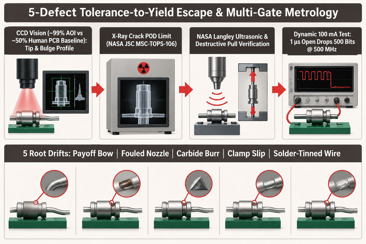
CCD vision systems inspect bent tips, off-center welds, and splayed strands. In PCB automated optical inspection benchmarks reported by Electronic Design, optical testing reaches up to 99% detection efficiency compared to roughly 50% for manual visual microscopy. Yet surface cameras remain line-of-sight blind to subsurface weld porosity and hidden four-point crimp cracks.
Cameras eliminate operator eye fatigue across repetitive small parts. Don Miller notes in Electronic Design’s AOI vs. X-ray analysis that a 1.3-megapixel CMOS camera across a 32 mm × 25.6 mm field delivers 25 µm pixel size. That 25 µm camera resolution suits general board-level surface flaws, whereas measuring 0.002 in (~51 µm) twist-pin bulge eccentricity requires higher telecentric magnification. Still, exterior lighting can’t inspect metallic fusion density underneath the gold surface.
Standard X-ray screening also has limited crack-detection capability unless it is calibrated for the specific defect geometry:
“Current X-ray methods provide adequate control for detection of volumetric flaws, but do not provide a high probability of detection (POD), and crack detection sensitivity cannot be verified for reliable detection.”
Qualified contact lines therefore combine automated CCD checks with destructive tensile pull testing and dry-circuit electrical sweeps. NASA Langley ultrasonic crimp testing confirms that visual exterior checks fail to prove pull retention and miss missing strands inside sleeve barrels. Likewise, Lectromec’s contact resistance research shows that static bench meters miss brief vibration opens completely. Lectromec illustrates that on a 500 MHz signal, a 1-microsecond continuity interruption drops 500 bits. MIL-DTL-83513 §4.5.14 monitors dynamic continuity with at least 100 mA test current flowing.
Why is a micro twist pin machine failing mating force or concentricity checks?
Mating force failures and tip eccentricity are usually attributable to four mechanical drifts: unequal spool payoff tension, fouled inert gas nozzles, worn carbide shear blades, and anti-helical clamp slip. Payoff drift bows wire blanks before laser welding and contaminated gas nozzles leave the melted sphere off center. Worn dies leave shear burrs and jaw slip crushes a spring waist.
Troubleshooting teams are able to isolate defects faster by tracing each one to its root cause with the defect matrix below than by readjusting all servo loops.
| Defect Mode | Observed Symptom | Root Station Variable | Detection & Escape Control Gate |
|---|---|---|---|
| 1. Strand Splaying / Birdcage | Loose outer wire flares at rear or tip nose | Dulled shear blade clearance or zero rear laser lock | Telecentric OD spike alert before waist-drumming |
| 2. Eccentric Weld Ball | Tip center shifts beyond sleeve chamfer clearance | Off-axis fiber focus or uneven clamp jaw wear | Coaxial backlit silhouette vision at JY01-03 |
| 3. Bulge HAZ Softening | Pin mates softly (<0.5 oz separation) after heat | Over-long laser dwell anneals TH04 wire toward TB00 | Mechanical gauge separation test & shorter ms pulse |
| 4. Sleeve Pull-Out Failure | Wire pulls clean under 5 lb tensile audit | Over-crimped strand nicking or partial barrel depth | AS22520 Go/No-Go gage + lot pull-to-failure |
| 5. Hidden Microsecond Opens | Static LLCR passes yet dynamic continuity fails | Subsurface porous weld tip or stressed tin-wicked core | EIA-364-28 vibration discontinuity + EIA-364-23 LLCR |
Why Solder-Tinned Wire Crimps Fracture: When operators tin leads before crimping, wire strands often break behind the crimp barrel during vibration test trials. Engineers on the EEVblog engineering discussions say NASA-STD-8739.4 §4.3.4 covers this.
“Crimping of … stranded wire that has been solder-tinned, is prohibited.”
Liquid solders wick up copper filaments, creating a brittle stress riser near the four-point indent. Contracts invoking the IPC/WHMA-A-620 Space Addendum strictly prohibit this practice.
Modeling First-Pass Yield and Line Capacity Sizing
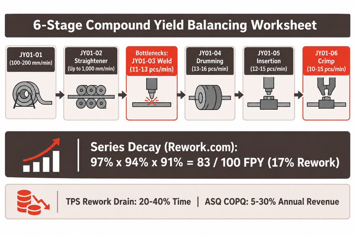
In manufacturing, actual cell capacity is constrained by two factors: Rolled Throughput Yield (RTY) and the cycle time of the slowest station. Ignoring cumulative fallout across serial stations overstates true shift output. When calculating machine sizing with yield, fallout must be accounted for to ensure tooling capital is utilized most effectively.
As Rework.com shows in manufacturing yield analysis, high single-step yields create false confidence. Rolled Throughput Yield multiplies each station pass rate together (RTY = FPY_1 × FPY_2 × … × FPY_n). Rework.com illustrates this across a three-step 97%, 94%, and 91% workflow yielding 83% (only 83 first-pass units per 100 started). Toyota Production System studies cited by Rework.com (Liker, 2004) find rework loops consume up to 20–40% of available production time, while ASQ estimates poor quality consumes 5–30% of annual manufacturing revenue.
Is an automated micro twist pin machine worth the investment for low-to-medium volume runs?
Yes, automated cells pay back at moderate volumes. Payback turns positive once manual rework, scrap, and zero-acceptance inspection labor exceed modular tooling amortization. Buyers can stage a six-machine setup gradually rather than buying all stations together. Automating dual-end laser welding or servo waist-drumming first stabilizes contact scrap immediately.
For line capacity sizing, use the 6-Stage Compound Yield Balancing Worksheet below anchored directly to published module cycle speeds on ZEUEE’s six-machine line. Speed of peak straighteners (up to 1,000 mm/min) doesn’t set limits on cell throughput; throughput is limited by discrete laser welding (11-13 pcs/min) and wire crimping (10-15 pcs/min).
| Station Sequence | Published Equipment Pace (ZEUEE) | Primary Process Control | Compounding RTY Bottleneck Role |
|---|---|---|---|
| 1. Stranding (JY01-01) | 100–200 mm/min continuous payoff | Laser OD gauge + magnetic tension | Feeds upstream blank concentricity into line |
| 2. Stress Relief Straightening (JY01-02) | Up to 1,000 mm/min linear feed | Fiber-optic stop + stress removal | Surges ahead of discrete cell steps; not pace cap |
| 3. Cut & Dual-End Laser Weld (JY01-03) | 11–13 pcs/min discrete cycle | Inert-gas weld + CCD tip ejection | Primary thermal pace bottleneck; gates downstream |
| 4. Servo Waist-Drumming (JY01-04) | 13–16 pcs/min indexed forming | Piezo feed + CCD bulge inspection | Monitors formed bulge geometry (0.002 in interval ref in US6584677B2); rejects bad blanks |
| 5. Housing Insertion & Crimp (JY01-05) | 12–15 pcs/min robotic seating | 4-axis robot + CCD size sorting | Protects pin alignment into molded shell ports |
| 6. Lead Wire Strip & Crimp (JY01-06) | 10–15 pcs/min lead termination | Servo encoder + multi-angle CCD | Co-bottleneck at terminal crimp; final serial FPY gate |
| Documented Series Math Benchmark (Rework.com) | 97% × 94% × 91% step yields | Multiplicative FPY chain | 83 / 100 first-pass completion (17% cumulative rework) |
Real shift net output reflects both the lowest machine pace (10–15 pcs/min or 11–13 pcs/min) and cumulative series rejects. Losses in a series line increase as multi-diameter wire swaps require additional collet swaps and camera recalibrations.
Line Capital Cost Drivers and Delivery Lead-Time Scope Boundaries
Public machinery catalogs omit uniform fixed pricing or standard delivery timelines for six-machine twist-pin cells. Online price estimates lack verified factory sourcing because custom non-standard automation is quoted strictly per buyer pin print. Instead, capital cost and lead time depend on six engineering scope variables across standalone units versus linked cells.
Key cost and schedule drivers include phased station count, standalone modules versus a 6-station line, plus custom tungsten-carbide collets across the wire-diameter range. The number of laser optics and CCD inspection cameras on a machine also impacts cost. Adding indexed cassette transfers and sample-wire repeatability runs at Factory Acceptance Testing (FAT) also shapes delivery windows. Prospective customers must provide sample wire reels and a pin print to the factory to get a quote for a custom scope and delivery window.
Supplier Qualification, RFQ Specs, and FAT/SAT Acceptance
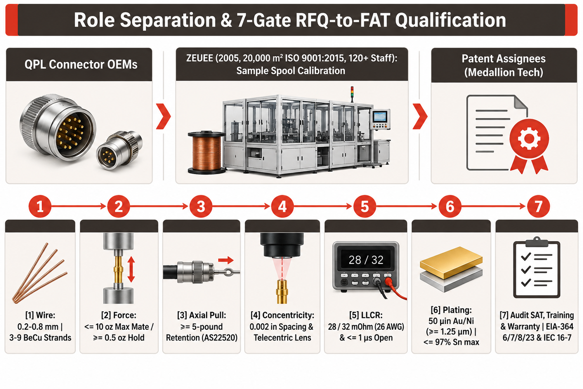
Supplier qualification starts by separating QPL connector manufacturers such as Glenair and Omnetics from dedicated contact-forming machine builders and patented equipment assignees. Connector OEMs also provide DLA-qualified connectors. By contrast, turnkey automation builders such as ZEUEE (six-station JY01-01 to JY01-06 cells) and anti-helical waist-drumming apparatus patent holder Medallion Tech LLC (USPTO US6584677B2) address stranding, bulging, tip welding, and vision sorting machinery.
Micro-D Procurement Guide for Twist Pin Contact Tool Kits and Sets
Before paying tooling deposits, buyers should bind machine builders to EIA-364 and IEC 60512 verification methods. Key procedures include EIA-364 Method 6 (contact resistance), Method 7 / IEC Test 16-7 (axial concentricity), Method 8 (crimp tensile), and Method 23 (LLCR). As published on ZEUEE’s company overview (founded in 2005, 20,000 square metre ISO 9001:2015 facility, 120+ staff, and 150+ listed R&D patents), ZEUEE delivers custom micro twist pin machine configurations calibrated directly against buyer sample spools. ZEUEE engineers run repeatability trials at Factory Acceptance Testing prior to shipping.
Copy these technical requirements into your quote requests so competing suppliers bid against the same tooling and inspection requirements:
RFQ checklist — copy these into your quote request:
| Parameter | Recommended range | Why it matters | How to verify |
|---|---|---|---|
| Wire Diameter & Strand Count | 0.2 mm to 0.8 mm bundle envelope; 3–9 BeCu strands | Sets wire straightener grooves, collet bores, and tension heads | Submit buyer sample test spools & drawing tolerance block |
| Mating & Separation Force | ≤ 10 oz max mate; ≥ 0.5 oz min hold (MIL Size 24 gauge) | Governs drum bulge outer diameter and TH04 spring elasticity | Sample test sleeve gauge check per MIL-DTL-83513H §3.5.7 |
| Axial Sleeve Retention & Pull | ≥ 5-pound retention; AS22520 crimp pull verification | Prevents contact pushback or hidden conductor drop under G-load | SAE AS22520 Go/No-Go gage & destructive pull test at FAT |
| Concentricity & Vision Calibration | Within 0.002 in bulge spacing; high-magnification telecentric optics | Eliminates skewed weld caps jamming automated sleeve feeders | EIA-364 Method 7 concentricity check & repeatability trial |
| LLCR & Dynamic Continuity | 28 mΩ (AS22759/11) / 32 mΩ (AS22759/33) max LLCR (26 AWG); ≤ 1 μs open | Exposes porous cold welds and intermittent shock drops | EIA-364-23 4-wire Kelvin test + dynamic discontinuity run |
| Plating & Alloy Constraints | 50 μin Au over Ni (≥ 1.25 μm Class 1.25); ≤ 97% Sn max | Stops tin whiskers and prevents solder-boil voids in laser tips | Plating thickness audit per ASTM B488 & raw alloy mill cert |
| After-Sales Commissioning & Spares | On-site SAT, operator training, machine spares package | Avoids startup downtime across carbide blades and collet wear sets | Audit delivery documentation for installation, commissioning, operator training, and warranty support |
Equipment builders perform Factory Acceptance Testing (FAT) and sign off the lot acceptance record (traceability) before export crating. Compliance with the equipment builder’s machining is separated from the customer’s QPL connector certification by written acceptance.
Integration, Changeover, and Utility Readiness
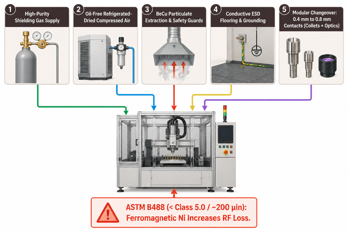
Before unboxing an automated contact line, facility teams must prepare oil-free air, high-purity shielding gas, conductive flooring, and modular tool sets alongside SAE AS22520 crimping tools so clean plant utilities support Site Acceptance Testing.
Unfiltered plant air coats vibratory feeder tracks in fine compressor mist. That oil film can foul BeCu wire tips before laser fusion. Irregular shielding gas flow can lead to tip welds appearing brown. Poor grounding can lead to ultra-light pins sticking to trays.
| Facility Subsystem | Target Operating Requirement | Pre-SAT Site Verification Check |
|---|---|---|
| Inert Laser Shielding Gas | Regulated high-purity inert gas feed at dual-end fusion nozzle | Verify dual-stage gas pressure gauge and zero moisture lines before welding |
| Clean Compressed Air | Oil-free, refrigerated-dried supply for pneumatic cassette transfer | Confirm point-of-use coalescing filter prevents oil fouling on pin bulges |
| Optical Guarding & Extraction | Interlocked laser enclosure + particulate exhaust hood for 1.80–2.00% BeCu | Confirm door interlock trip and local fume extraction airflow capture at weld zone |
| ESD Grounding & Tray Interface | Static-dissipative bench mats + indexed cassette / plating baskets | Verify ground bond to chassis and carrier compatibility for smart factory upgrades |
| Modular Tool Kit & Spares | Quick-change collets, shear blades, and machine engineering tools per pin diameter | Label application-specific tool set drawers (e.g., 0.4 mm vs 0.8 mm kits) before batch swaps |
ZEUEE’s 6-machine configuration also handles rapid diameter changeovers between 0.4 mm signal contacts and 0.8 mm pins without structural rebuilds. Plating teams must verify both silver-exclusion barrier rules and RF underplate attenuation on contacts from robotic lines. ASTM B488 requires nickel underplating under gold over copper alloys for Classes below 5.0 (~200 µin). However, the use of ferromagnetic nickel increases high frequency RF insertion attenuation compared to non-magnetic gold, which makes an alternative barrier selection critical for RF contact pins.
Frequently Asked Questions
1. What MIL specifications govern contacts made on a micro twist pin machine?
MIL-DTL-83513 Revision H Amendment 2 defines Micro-D connectors on 0.050 in contact centers, and MIL-DTL-32139 Revision B Amendment 3 specifies Nano-D connectors on 0.025 in contact centers. Under MIL-DTL-83513, contacts require 10 oz max mating force, 5-pound axial retention, 500 mating cycles durability, and a separate -55 °C to +125 °C operating range. Gold plating is done in accordance with MIL-DTL-45204 Type II, Grade C, Class 1, over a non-silver underplate. Pure tin finishes are prohibited. Any tin alloy plating must consist of no more than 97% tin by mass, and must have 3% lead or greater. Smaller mechanical limits are set in MIL-DTL-32139.
2. Can a single twist pin forming line process both 0.050 in Micro-D and 0.025 in Nano-D contacts?
Yes, one modular cell processes both 1.27 mm pitch Micro-D contacts and 0.64 mm pitch Nano-D connector contacts, within the ZEUEE Micro-D to Nano-D wire diameter range, without rebuilding the hardware. Precision shear dies made of tungsten carbide are specified along with tighter guide bushings and narrower straightener rollers in tooling kits. Operators also load shorter laser weld pulse widths to protect tempered C17200 springs and switch telecentric CCD lens magnification settings during each Nano-D batch changeover.
3. Do connector factories need to automate all six twist-pin stations at once?
No, factories can deploy standalone modules first rather than purchase the whole set of six automated machines in a single batch. ZEUEE supplies individual stations built to operate standalone or link later via indexed cassettes and vision trays. Most engineering teams automate their highest scrap step first, usually dual end laser welding or servo waist drumming, validate yield improvements on sample wire coils, and stage housing or lead wire crimping cells during follow on expansion phases.
4. Why does a contact pass CCD vision inspection yet fail mating force testing?
Telecentric cameras inspect bulge external geometry while missing alloy softening inside the heated tips of the wire. Annealing C17200 drops tensile strength from 212 ksi to 68 ksi and further weakens spring force.
5. What raw wire alloy and plating specs apply to MIL-grade micro twist pins?
MIL-DTL-83513 contacts pair cold-worked UNS C17200 beryllium-copper spring wires (1.80–2.00% beryllium, 22% IACS conductivity) with copper-alloy cores for repeatable contact wiping elasticity. Electrodeposition applies gold over nickel underplating per MIL-DTL-45204 Type II Class 1 (~50 µin) or ASTM B488 Class 1.25 minimums, avoiding banned silver barriers. Control of alloy cleanliness prior to tip laser welding ensures volatile residues do not enter the molten dome during inert gas fusion.
6. How do twist pin cycle ratings compare with female hyperboloid sockets?
According to MIL-DTL-83513, male twist pins must sustain 500 mating cycles minimum, while female hyperboloid wire sockets, of a different contact type, sustain up to 100,000 cycles with no increase in resistance.
7. What sample artifacts should an engineering team send before requesting a line feasibility trial?
Before quoting a custom cell, engineering teams should submit production wire spools specifying alloy temper, full contact prints with diameter tolerances, mating test sockets, and daily shift targets. Having the customer wire allows machine builders to validate residual spool cast memory, tungsten-carbide shear quality, laser pulse settings and CCD contrast before releasing custom collets or optical fixtures for FAT build completion.
Scope Your Twist-Pin Engineering Review
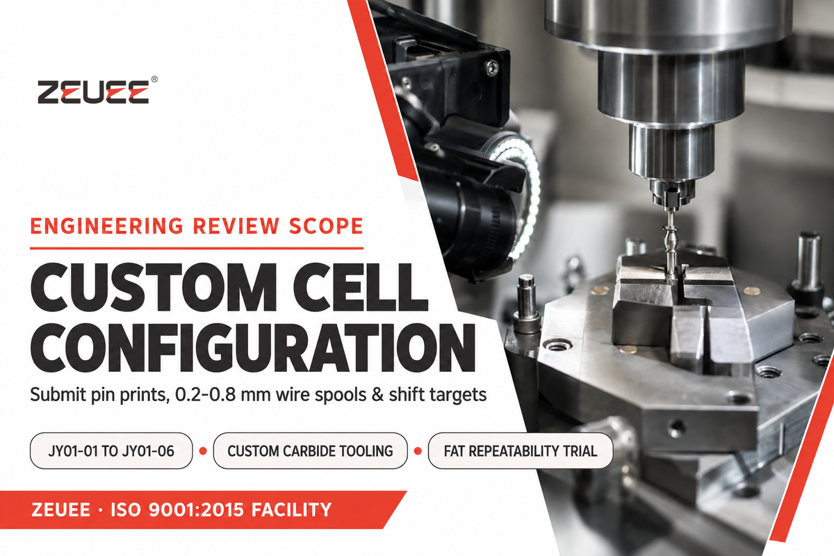
Custom modules, contact-point tooling, and throughput architecture should be evaluated on ZEUEE’s automated micro twist pin machine solution page. Send your contact drawing, wire diameter (0.2 mm to 0.8 mm), and shift targets to solicit a ZEUEE line review.
Technical Scope of This Process Guide
This engineering guide examines forming tolerances and yield physics of C17200 laser metallurgy in MIL-DTL-83513 and MIL-DTL-32139 contact manufacturing. The publication is by ZEUEE. Our automation specialists build stranding, cutting/welding, bulging, and vision inspection systems across a 20,000 m² facility. This has been reviewed by the Shenzhen Zeyu Intelligent Industrial Science Technology Co., Ltd. technical team.
References & Sources
- MIL-DTL-83513 Revision H Amendment 2 Specification Index (Sept 2023) Defense Logistics Agency ASSIST
- MIL-DTL-32139 Revision B Amendment 3 Nano-D Specification Index (Sept 2026) Defense Logistics Agency ASSIST
- X-Ray Crack Detectability (MSC-TOPS-106) Nondestructive Evaluation Boundaries NASA Johnson Space Center
- Ultrasonic Crimp Wire Pull Integrity & Failure Pathologies (NF1676L-19599) NASA Langley Electrical Engineering
- USPTO US3258736A: Helical Resilient Multi-Wire Connector Contact IBM (1966)
- USPTO US6584677B2: Continuous Anti-Helical Bulge-Forming Apparatus Medallion Tech LLC (2003)
- Copper Alloy C17200 Wrought Beryllium Copper Datasheet Copper Development Association
- SAE AS22520: Crimping Tools & Wire Termination General Specification SAE International
- Mei et al. (2023): Copper Laser Welding Trajectory, Spatter & Porosity Suppression Optics and Lasers in Engineering
- Mousavi & Niknejad (2010): Pulsed Nd:YAG Welding & Aging of 0.2 mm Cu-Be Alloy Journal of Materials Processing Technology
- Kitagawa et al. (Sept 2026): Review of Laser Beam Oscillation Amplitude & Stability Limits Journal of Materials Processing Technology
- What Are MIL-DTL-83513 Connectors? ConnectorSupplier
- Micro-D Connectors: Engineering Guide to MIL-DTL-83513 Interconnects Military Embedded Systems
- What Is Hyperboloid Contact Technology? ConnectorSupplier
- What Is the IPC/WHMA-A-620 Space Addendum? ConnectorSupplier
- Exploring AOI and X-Ray Inspection Capabilities Electronic Design
- Connector Contact Resistance & Dynamic Microsecond Discontinuity Testing Lectromec
- ASTM B488 Gold Plating Thickness Classes for Aerospace Connectors Valence Surface Technologies
- EIA-364 to IEC-60512 Connector Test Crosswalk Experior Labs
- First-Pass Yield & Rolled Throughput Yield Mechanics Rework.com
Related Articles
- Waist-bulge engineering and tolerance stack-up servo drumming controls for contact force repeatability
- Four-point twist pin crimping tolerances sleeve retention and pull-to-failure inspection rules
- Automated connector vision inspection methods telecentric lighting setups and defect rejection sorting
- Micro-D connector architecture and assembly overview MIL-DTL-83513 hardware configurations
WHY WE WRITE THIS
About ZEUEE Engineering Insights
ZEUEE shares technical guides based on real automation project experience. Since 2005, we have designed and manufactured non-standard automation equipment for connector assembly, wire harness production, robotic lines, vision inspection, and smart factory upgrades.
Founded in 2005
20,000 m² production base
120+ specialists
150+ R&D patents
ISO9001:2015 certified
Trending now