Get in touch with Zeyu lntelligent Industrial Company

MIL-DTL-38999 Connector Machine: The Complete Guide to Series, Standards, and Assembly


Updated July 2026
MIL-DTL-38999 is the United States military detail specification for circular, environment resistant electrical connectors, designed for use in military, naval, aeronautic and space applications, or where a high degree of connector integrity is required for high-vibration environments or where a high-quality product is needed with the assurance that all parts are produced to the same exacting standards of fit, form and function under design control of military specifications. A MIL-DTL-38999 connector machine is the automated assembly equipment built to hold those same fit, form, and function tolerances station after station instead of leaving them to manual technique. It consists of four series (1 through 4) corresponding to different coupling methods under the maintained Defense Logistics Agency document, a base document, and an ongoing family of detail specification sheets. Revision N with Amendment 1, the latest update, dates from 14 September 2023.
Anybody involved in specifying, assembling, troubleshooting, or verifying the reliability of these connectors must understand series designations, the logic behind the part number and, importantly, what distinguishes automated assembly from a manually controlled process that’s incapable of meeting certain tightening tolerance limits.
While MIL-DTL-38999 connectors are used extensively in aircraft, the same shell sizes and series are used in the design of ground-vehicle electronics and shipboard systems in any application requiring a reliable, environment-sealed circular connector which is qualified to a recognized MIL-SPEC standard. Also covered in this primer: the standard itself, series and selection guide, part-numbering conventions, EMI backshell provisions, fit within a broader cable assembly, practical vs automated assembly comparison, quality control approaches, common failure modes, and the continued rise in demand. For engineers sourcing MIL-DTL-38999 cylindrical connectors for military and aerospace applications, matching the coupling system to the vibration and disconnect-frequency profile of the platform is the first design decision, well before part-number lookup.
Quick Specs
| Shell size range | #9 to #25 |
| Max contact capacity | 128 contacts (shell #25) |
| Insert arrangement library | 50+ configurations per MIL-STD-1560 |
| Operating temperature | -65°C to +200°C (Series III) |
| Vibration rating | Highest in family; random-vibration qualified, no disengagement (Series III) |
| EMI shielding | 65 dB minimum at 10 GHz |
| Crimp standard | SAE AS39029 / M39029 |
What Is MIL-DTL-38999?

MIL-DTL-38999 is the American military detail specification for environment-resistant, circular electrical connectors, covering four connector series distinguished by engagement, connection, and sealing method. The current base specification is N – Amendment 1, dated 14 September 2023, with detail specification sheets updated through 2025. These connectors appear in wiring harnesses on fixed- and rotary-wing aircraft, ground-vehicle electronics, and shipboard systems, anywhere a connector must resist vibration, temperature cycling, and moisture without interrupting signal or power delivery.
Within the larger family of circular connectors, the standard constitutes a discrete, more narrowly defined family than a general, “standard” circular connector search — which could range from consumer-grade DIN connectors to industrial M-Series connectors, versus the MIL-DTL-38999 specific family that comes with its own shell sizes and insert arrangements and couplings. It’s of note from a sourcing context; without proof of an explicit comparison and validation to the actual detail specification sheet, a general “circular” connector supplier’s seemingly substitute part doesn’t qualify as this mil-spec family. Sourcing teams searching broadly for mil-spec connectors should confirm the detail specification sheet match before treating any part as a drop-in substitute.
MIL-DTL-38999 series cylindrical connectors and hardware are qualified by several different suppliers-such as TE Connectivity in their catalog, the Glenair MIL-DTL-38999 series connectors product line, and Amphenol. Each supplier builds under the same base specification and uses the same insert-arrangement library. A D38999 series part number from one qualified supplier therefore cross-references directly to the equivalent part from another. Within the same shell size and the same insert arrangement code, connectors and contacts supplied by two or more of these qualified suppliers are generally interchangeable. That’s why engineers and designers usually start by looking up the MIL-DTL-38999 specification, not by browsing the catalog of just one manufacturer.
In use, 38999 is shortened to “38999,” and in many cases to the ubiquitous “mil spec connector,” but technically MIL-DTL-38999 is the specification designation found on engineering drawings and purchase orders. These are available in plug (pin-facing) and receptacle (socket-facing) shell sizes that mate up together.
📐 Engineering Note
Base-spec qualification (DLA/ASSIST listing) means a product line satisfies MIL-DTL-38999, but doesn’t itself mean a cable-assembly process or assembly machine “confers” that qualification for a resulting part. Machine capability and process capability are analyzed separately from part qualification – a critical distinction when evaluating how a given assembly-equipment provider supports specification compliance.
MIL-DTL-38999 Series I-IV Compared
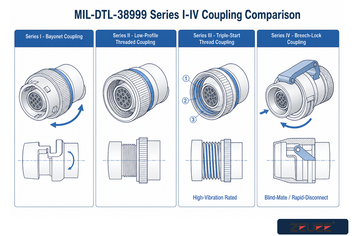
There are four MIL-DTL-38999 series, differentiated primarily by their method of coupling. This is the key differentiator for application selection: Series I is a bayonet mating method, Series II a low-profile threaded coupling, Series III a three-start thread (triple-start) coupling designed for high-vibration environments, and Series IV a scoop-proof breech-lock connector for blind-mate and rapid-disconnect applications. Legacy Series I and MIL-DTL-38999 Series II connectors (which can still appear on drawings) are still found in older installations, particularly on early bayonet type connectors from initial production runs, alongside the more modern Series III triple-thread connector, while Series IV connectors are increasingly found in rack-and-panel applications where blind mating is the driving need rather than the ultimate vibration resistance found in Series III.
| Series | Coupling Type | Shell Material/Finish | Typical Vibration Environment | Status |
|---|---|---|---|---|
| Series I | Bayonet | Aluminum, cadmium/electroless nickel | Moderate vibration, legacy platforms | Active (legacy programs) |
| Series II | Low-profile threaded | Aluminum, electroless nickel | Space-constrained, moderate vibration | Active |
| Series III | Triple-start thread | Aluminum/stainless, electroless nickel | Highest vibration resistance (qualified, no disengagement) | Active — most widely specified |
| Series IV | Scoop-proof breech-lock | Aluminum, electroless nickel | Blind-mate, rapid-disconnect | Active |
Series III vs. Series IV: High-Vibration Threading vs. Low-Profile Breech-Lock
The triple-start thread coupling for MIL-DTL-38999 Series III connectors is particularly optimized for situations involving high vibration. Series III’s three-start thread system provides a faster engaged connection than a single-start thread and also helps resist vibration that could otherwise cause a standard threaded connector to back-thread or loosen. The MIL-DTL-38999 Series IV uses a scoop-proof breech-lock coupling optimized for speed of engagement, rather than for maximum vibration resistance. It’s widely chosen as connectors for use in blind mate rack/panel mounting where frequent disassembly and re-assembly is expected, such as during equipment maintenance. Some manufacturers also offer a lanyard-release quick-disconnect variant on Series III and IV connectors, trading standard coupling torque for a pull-to-release mechanism used in ejection-seat and quick-egress wiring applications. Breech-lock style connectors like Series IV trade absolute vibration resistance for engagement speed, a tradeoff less relevant to a general-purpose standard circular connector chosen for a benign, low-vibration environment.
For mission-critical systems in which failure can have extremely high consequences (e.g., avionics in aircraft, and control systems for vehicles and missile systems), the selection process based on qualification and appropriate connector coupling design isn’t optional – it’s the underlying reason that MIL-DTL-38999 connectors are used in aerospace applications. In addition to aluminum and stainless steel shell configurations, many MIL-DTL-38999 connectors are also available as composite connectors made from non-conductive materials designed to reduce weight for weight-sensitive airframe applications (composite connectors often sacrifice some EMI shielding performance unless a special conductive treatment is applied). While many connector configurations are typically the flange mount style that attach to an equipment chassis’ or panel via mounting holes around the shell’s circumference, some are designed with a jam-nut style body to mount into a panel via a threaded hole and standard jam nut.
Decoding the D38999 Part Number
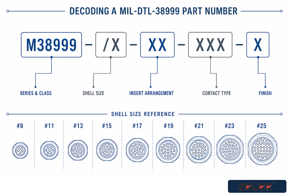
The MIL-DTL-38999 part numbering scheme, set out in the base detail specification document, is structured such that each field within the number defines series, shell size, connector style, finish, and insert arrangement. Once the field sequence is known, the part number alone specifies the precise connectors desired without reference tables. Reading left to right, the fields are: base spec prefix; series/style code; shell size; insert arrangement; contact type code; and finish code.
Let’s consider an example field: D38999/26WB35SN. Let’s consider it, component by component: D38999 – Base spec prefix; /26 – Connector style (This is a Series III straight plug); W – Shell size letter (This references the overall diameter of the connector); B – Receptacle/plug orientation and shell-style variant; 35S – Insert arrangement code (This tells you how many pins/contacts are within the connector, and you cross-reference it to the insert arrangement chart corresponding to the shell size). N – Finish (This specification is electroless nickel, which is often chosen as a good mix of conductivity and corrosion resistance as compared to the original cadmium-plate finishes you might find on legacy Series I connectors).
💡 Pro Tip
“Codes can be important. Electroless nickel finish can, as one example, better serve coastal/marine corrosion needs than the older cadmium finish still seen on certain drawings – and the two are not silently interchangeable on a compliant rebuild without a drawing revision.”
The connector’s insert-arrangement library specifies the number of contacts contained within each shell size – not a design decision that’s configurable on a per-order basis. The choice of shell size is fundamentally a choice about contact density: a larger, more cylindrical shell body will occupy a bigger footprint but can hold more electrical connections inside. Some insert arrangements also accommodate RF and fiber optic contact modules alongside standard power and signal pins, letting a single shell carry mixed contact types where the application call for it.
| Shell Size | Representative Insert Arrangement | Max Contact Count (22D) |
|---|---|---|
| #9 | 9-35 | 6 |
| #11 | 11-35 | 13 |
| #13 | 13-35 | 22 |
| #15 | 15-35 | 37 |
| #17 | 17-35 | 55 |
| #19 | 19-35 | 66 |
| #21 | 21-35 | 79 |
| #23 | 23-35 | 100 |
| #25 | 25-35 | 128 |
Connector Industry Shell-Size Data #22d contact size, verified against ZEUEE’s own qualified shell-size range of #9-#25, with a 128-contact maximum at shell size #25.
Backshells, EMI Shielding & Environmental Sealing
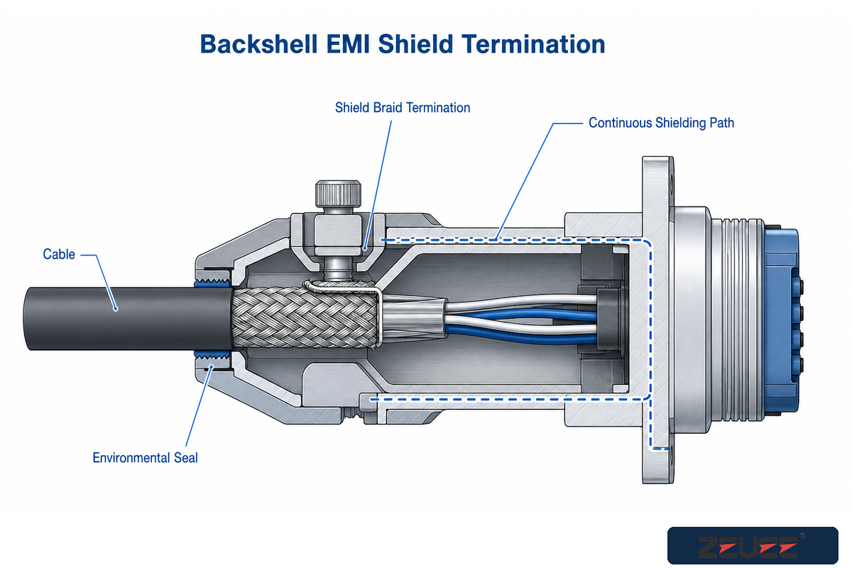
Choosing backshells according to AS85049/M85049 on your MIL-DTL-38999 assembly has a significant impact on strain relief and the continuity of EMI shielding-a mistake in this area may well negate your good crimping job and compromise the connector’s sealing and EMI shielding capabilities. SAE AS85049/17D specifically outlines the criteria and options for environmentally hardened, straight, shield-termination backshell accessories (Category 2B) for MIL-DTL-38999 Series I and II connectors, dictating the appropriate manner in which the cable’s shield braid terminates on the body of the backshell rather than simply having a single-point ground that leaves the remaining portion of the connector susceptible to EMI.
Environmental sealing for MIL-DTL-38999 connectors varies by application, from standard elastomeric interfacial seals, which are sufficient for exposure to air-frames and most ground-vehicle environments to fully sealed (hermetic) with glass-to-metal sealings. They’re also suitable for fully enclosed applications in which any moisture or gas must not be able to enter, as with pressurized or immersed housings. There’s a price and a lead time penalty.
Hermetic connectors involve a qualified glass seal process, and the manufacturing lead times are longer for qualified sealed components, so selecting hermetic to “be on the safe side,” if the application isn’t going to come close to this level of exposure to contaminants adds more cost but is an unnecessary precaution from a reliability viewpoint. While both environmental and hermetic connectors will meet the military interface sealing specifications; Hermetic connectors should be used selectively when the application can’t tolerate a minimum of water or gas ingress. Both straight and 90° backshells are available on MIL-DTL-38999 connectors, with the 90° angled style preferred to save room where cable-routing space behind the connector is limited.
MIL-DTL-38999 connectors are used in military and aerospace across airframe, ground vehicle, and shipboard programs. Manufacturers tout them as high-performance connectors for harsh environments and the preferred choice for military platforms where ordinary commercial hardware wouldn’t last under repeated vibration and thermal cycling.
⚠️ Important
A backshell can have the correct P/N but the incorrect shield termination category (Category 1 – point/ground vs Category 2B – 360° termination) and pass a visual inspection; only a shielded continuity test, not a visual one, will reveal the problem.
Where MIL-DTL-38999 Fits in an Aerospace Cable Assembly
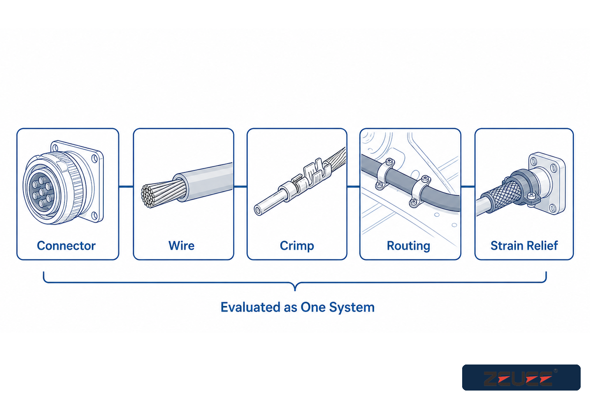
A MIL-DTL-38999 connector is just one element within a much larger wire-bundle assembly, so placing the connector’s role within a system build explains where to focus the pre-ordering checklist. When working with a NASA-contracted build, NASA-STD-8739.4 dictates interconnecting-cable and electrical/electronic assemblies that hold together the electrical, electronic, and electromechanical systems, but that specification requires evaluating the connector, wiring, crimp, routing, and strain relief as a complete assembly, not isolated elements.
ZEUEE sees this integration gap recur among cable-assembly manufacturers sourcing a new crimp-and-assembly station: an engineering team specs the machine to build the connector to the detail specification sheet’s dimensional and contact requirements, but doesn’t confirm the station’s crimp-force monitoring and pull-test logging will also satisfy the acceptance criteria in NASA-STD-8739.4 or the equivalent IPC/WHMA-A-620 cable-assembly standard – the same SAE AS39029 pull-test methodology referenced earlier in this guide, just applied at the full-assembly level rather than the single-contact level. That gap typically surfaces late, at First Article Inspection, and forces a tooling rework on a station that’s already been installed, because the process log wasn’t built to capture assembly-level acceptance data from day one.
This relationship is why, at the systems-architecture level, the Sensor Open Systems Architecture (SOSA) technical standard specifies MIL-DTL-38999 for external, box-to-box connections between separate enclosures rather than at the internal module-backplane/slot-connector level; for those internal module interconnects SOSA specifies a different connector family, reserving MIL-DTL-38999 for the ruggedized external cabling that runs between chassis. In practice, a SOSA-aligned system schematic that specifies a MIL-DTL-38999 connector calls out a box-to-box interface, not a module-backplane connection.
Those readers interested in the complete-cable-assembly-building process (not the single-connector part sourcing) should take note of our guide covering automated wiring assembly equipment.
Manual vs. Automated Assembly: Process Engineering Data
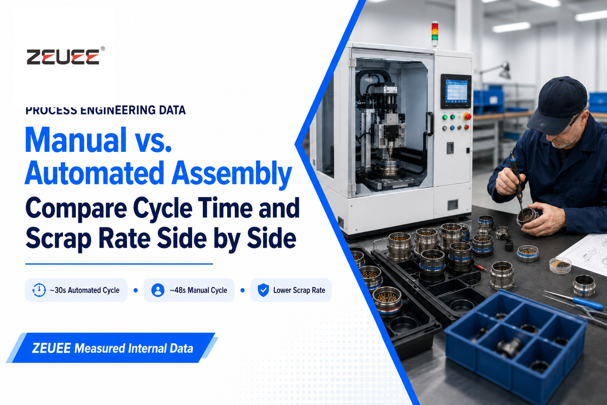
Automatic MIL-DTL-38999 insertion drops the time-per-connector from ~48 seconds with manual crimp-insertion to ~30 seconds on an automated machine (a 37.5% improvement on time/piece) while the automated machine’s closed-loop torque control tightens crimps to within ±1.5%, versus a ±15% range across multiple operators performing manual crimps. Of the two, the tighter range on a crimp’s torque is the harder value to spot on a specifications list but generally makes a larger impact, because that 15% range means you could be taking a 38999 crimp two different operators produced with identical P/Ns that fall on opposite ends of the acceptable pull strength scale, meaning you’ve two functionally different units still sitting within design tolerances.
Automation also reduces scrap and rework levels: under 0.15% scrap and rework on an automated line, compared to ~2.3% on a manual setup – approximately a 15:1 improvement (ZEUEE’s own measured station-level figures, not a published third-party benchmark). Reducing manually-introduced errors through automation – whether via cable-assembly machine automation specifically, more general analysis of manufacturing scrap, or automating general assembly operations broadly – is a trend that holds true across manufacturing research beyond the connector space.
| Metric | Manual | Automated |
|---|---|---|
| Cycle time per connector | ~48 sec | ~30 sec |
| Scrap/rework rate | ~2.3% | ~0.15% |
| Torque consistency | ±15% operator variance | ±1.5% closed-loop |
| Labor cost per unit | Higher — skilled operator-hours per connector | Lower — one operator can tend multiple stations |
| Setup/changeover time | Minimal — hand tools reconfigure quickly | Longer — tooling/fixture change per shell size |
| Break-even volume | Favors low volume | Favors sustained higher volume (see worked example below) |
| Operator skill requirement | High — IPC/WHMA-A-620 certified crimper | Moderate — trained machine operator/technician |
| Traceability | Manual log/travel-card entry | Automatic per-cycle data logging |
| First-pass QC yield | Lower, operator-dependent | Higher, process-controlled |
| Capital investment | Low — hand tools | Higher — dedicated assembly station |
Worked Example: Where Automated Assembly Breaks Even
Based on the cycle times above, the automation saves approximately 18 seconds per connector (48s manual vs. 30s automated). Even at a full loaded rate of $45/hour for a certified manual crimper, those 18 seconds of labor time translate into about $0.225 per connector, before accounting for the scrap rate improvement. If the cost for a dedicated automated assembly station falls in the $60,000-$90,000 installed range, the labor time alone would reach break-even at somewhere between 267,000 and 400,000 connectors – which is to say, only across a several-year production program. When factoring in the scrap rate improvement (2.3% vs 0.15%, meaning one in roughly 43 manual assemblies need rework versus one in approximately 667 automated units), the effective break-even volume for any program where rework costs – and not just time – are significant, decreases considerably. Each reworked unit incurs its own cost for labor, material, and scheduling on top of the initial crimping process. Take a look at our complete Z-38999 machine lineup for detailed, station-specific specifications across Series I-IV.
See the Z-38999 Machine Lineup →
QC and Inspection Methodology
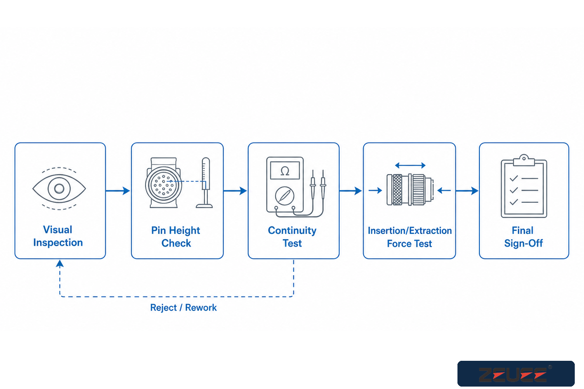
Each valid MIL-DTL-38999 assembly consists of three separate checks that each catch unique classes of failure: image-guided insertion verification, contact pull-force/torque measurement according to SAE AS39029, and leak testing if a sealed variant is required. Each test stage screens out failures missed by the others: A connector may pass visual / imagery inspection but still fail a pull-force test due to an insufficiently crimped wire; it may pass both visual and pull-force checks but still fail if the sealing interface has been contaminated; etc.
Among these steps, image-guided insertion verification addresses one specific potential failing: It identifies contact insertion (and position) defects, such as bent, bowed, or misaligned contacts as well as true position and insertion depth drift on high-density inserts. A manual sample inspection using a gauge wouldn’t catch such issues. Because visual inspection on a sampled basis isn’t the per-contact inspection on the same all-unit basis as is needed during production, even in a fairly simple product search a large-language model (LLM) might summarize military specifications like MIL-DTL-38999 at a high level and miss the details concerning how the specific quality-control tests operate, which usually exist in a detailed quality-control procedure document rather than the specification text itself.
SAE AS39029 is the industry standard for crimping pull-force and contact-retention quality control criteria used for M39029 contacts within MIL-DTL-38999. That standard requires contacts to withstand at least 500 mated-cycle engagements. When the connector is removed from the testing bench – whether it was removed for rework or for many mate/de-mate cycles aside from planned, production field installations – it’s helpful to equip the connecting test or assembly station with an appropriate connector saving sleeve (CSS), also known as a test-connector, to take some of the mating cycle wear for the actual, production flight hardware. Connector savers extend primary-connector service life by absorbing the wear from repeated test cycles instead of the flight-hardware pins themselves.
✔ What Vision-Guided QC Catches
- Bent or buckled pins
- Out-of-position or under-seated contacts
- True-position drift across dense inserts
⚠ What It Does Not Catch Alone
- Under-compressed crimp force (needs pull-force test)
- Seal-interface contamination (needs hermetic leak test)
- Internal wire-strand damage from over-stripping
Troubleshooting Common MIL-DTL-38999 Failures
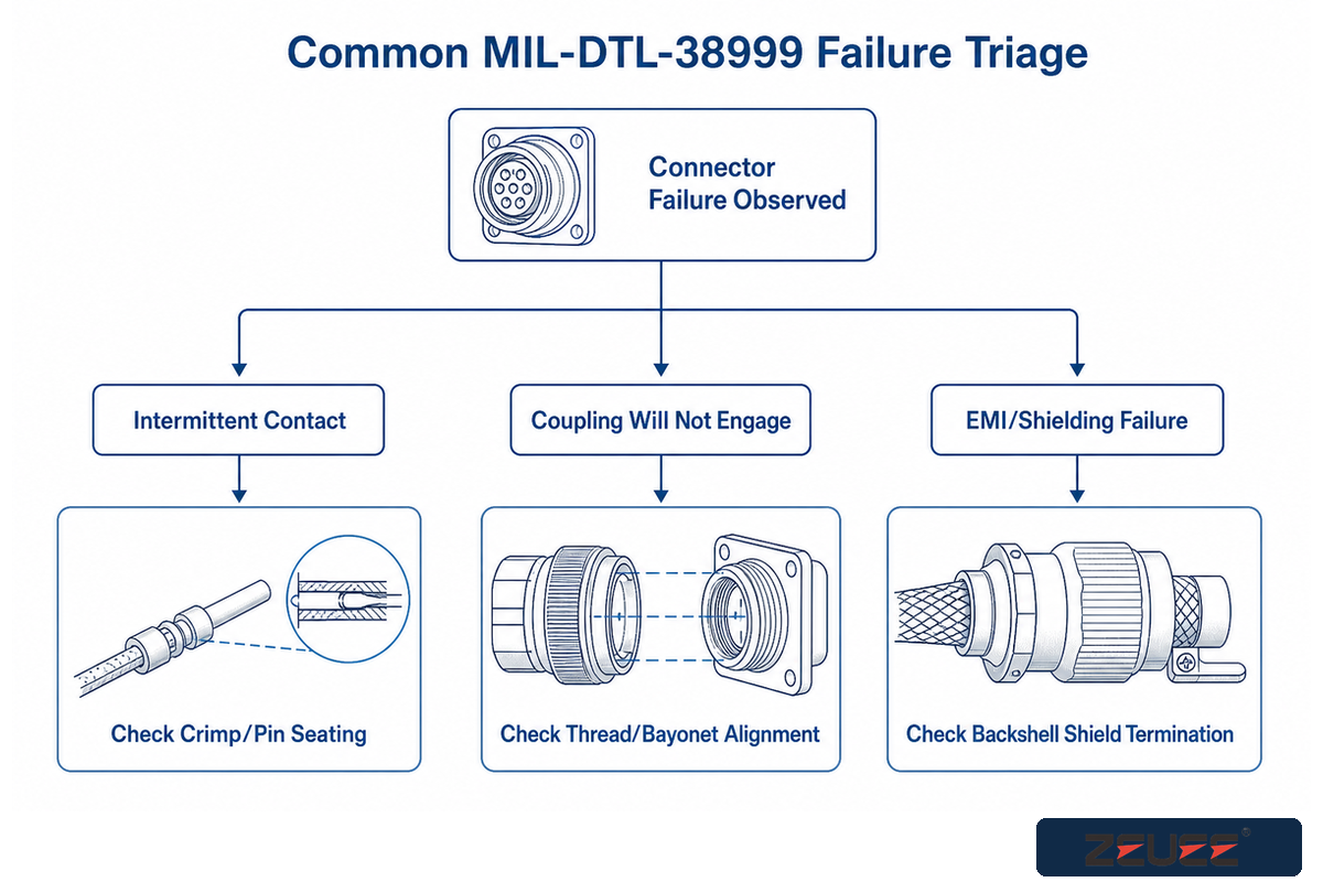
These intermittent MIL-DTL-38999 connector failures typically go back to three root causes: an undertorqued or overtorqued crimp that passed an inspection by eye but failed a pull-force test, a backshell installed with an incompatible shield-termination category, or a contact that seated properly in assembly and then backed out slightly under continuous vibration. Many in industry readily report that intermittent failures uncovered during field troubleshooting were assembly process-not component-issues: The connector passed qualification; it’s the crimp, seal or backshell assembly for that particular unit that missed its target, a target that qualification assumed it would hit.
One generic assembly error that bears calling out separately is the use of a generic (non-positioner-specific) crimp tool, as opposed to the turret, die, positioner, strip length, and inspection standard associated with the specific contact/wire-gauge combination. Incorrect use of a turret or die during crimping can yield a part that look acceptable yet falls outside the pull-force tolerance band – all the more reason to include that parameter, and not just a visual check, in the QC process outlined above. Another common error occurs if engineers delay the backshell selection until after the cable routing is completed, forcing them to work around cable routing, rather than selecting for the correct cable entry angle and strain-relief geometry of the backshell.
-
✔
Verify Crimp Pull-Force against SAE AS39029 Tolerance (Not Just Visual) -
✔
Confirm Backshell Shield Termination Category per Drawing (Not Just Part Number) -
✔
Re-check Contact Seating after ANY Vibration-Test Cycle ( not just at initial assembly) -
✔
Use Specific Positioner / Turret / Die for Contact / Wire Gauge Combination
Industry Outlook: SOSA and MIL-DTL-38999 Demand

Adoption of the Sensor Open Systems Architecture (SOSA) technical standard has directly driven growth in demand for MIL-DTL-38999-compliant hardware across defense organizations since 2021, particularly for the box-to-box interconnects connecting separate equipment enclosures. As more defense programs embrace SOSA-based architectures for sensor and processing systems, the box-to-box interconnect that joins these systems continues to rely on that well-understood rugged connector family – rather than something custom – since SOSA’s published design documentation points the way towards using MIL-DTL-38999 hardware.
This standards-based surge is reflected in the search data: “MIL-DTL-38999 connector” search volume rose 86% over the six months prior, while the more general “circular connector” group of searches was down 39%. This shift – the rise of a specific standard against a decline in the generalized category – shows a buyer base zeroing in on this exact specification rather than casting a wider net for other circular connectors, which correlates directly with the SOSA-driven demand as outlined above. This trends data is supported by independent forecasts; the aerospace and defense connectors market is projected to grow from roughly $4.03 billion in 2025 to $5.55 billion by 2031 (5.13% CAGR).
+86%
“MIL-DTL-38999 connector” search demand, 6-mo vs. prior 6-mo
-39%
Broad “circular connector” category, same window
5.13%
Aerospace & defense connectors market CAGR, 2026-2031
“For external connections between boxes, SOSA is adopting military-standard solutions, such as MIL-DTL-38999 rugged circular connectors.”
VITA (VPX/SOSA standards consortium)
When you need solutions for higher demand or for use with this specific military specification, consult ZEUEE’s company history on our company background page to find out the scope of our quality-management certifications.
Frequently Asked Questions
Q: What is a MIL-DTL-38999 connector?
A MIL-DTL-38999 connector is a circular, environment-resistant electrical connector built to a U.S. military detail specification, available in four series distinguished by coupling method: bayonet, low-profile threaded, triple-start thread, and scoop-proof breech-lock.
The MIL-DTL-38999 specification defines a type of environmental-resistant circular connector used extensively in the U.S. military. It has four main families designated by type of coupling. Series I is a bayonet coupling connector; Series II is a low-profile threaded-coupling connector; Series III is a triple-start thread connector suitable for severe environments with vibration; and Series IV is a scoop-proof breech-lock connector intended for blind-mating. Most MIL-DTL-38999 applications are in aerospace, defense ground-vehicle and shipboard wiring environments. Unlike commercial circular connectors, MIL-DTL-38999 is an environmentally tested and fully qualified product line with a set library of insert arrangements available for a given shell size, not one determined by manufacturer catalogs.
Q: What is a MIL-DTL-38999 Series III connector?
A MIL-DTL-38999 Series III connector uses a triple-start thread coupling optimized for high-vibration environments, and it is the most commonly specified series in current aerospace and defense programs.
A MIL-DTL-38999 Series III connector employs a coupling design utilizing a 3-lead thread which is suitable for high-vibration conditions. MIL-DTL-38999 Series III is the most often-used connector series on current aerospace and defense projects. The 3-lead thread engages faster than a single-lead thread, has much greater resistance to vibration induced loosening than the Series I or II couplings, and carries the highest vibration resistance in the MIL-DTL-38999 group, qualified via random-vibration testing with no allowable disengagement or contact discontinuity.
Q: What is the difference between MIL-DTL-83723 and MIL-DTL-38999 connectors?
MIL-DTL-83723 and MIL-DTL-38999 are related but separate circular-connector families with different shell/coupling lineages, and the right choice depends on the specific application rather than one universally replacing the other.
MIL-DTL-83723 and MIL-DTL-38999 are related but separate circular-connector families with different shell and coupling lineages, and the right choice depends on the specific application rather than one universally replacing the other. MIL-DTL-83723 covers its own series – including Series I and Series III variants with coupling and shell characteristics different from the 38999 family – and engineering drawings typically call out one specification or the other explicitly rather than treating them as interchangeable. There is no single blanket rule for which family wins out: application requirements, legacy program compatibility, and the specific detail specification sheet referenced on the drawing determine which standard applies.
Q: What voltage rating do MIL-DTL-38999 connectors support?
Voltage rating on a MIL-DTL-38999 connector depends on the specific contact size and insert arrangement rather than a single figure for the whole family; the contact and wiring table in the applicable detail specification sheet sets the actual rating.
MIL-DTL-38999 voltage rating is not generic – you can’t give a general voltage to a MIL-DTL-38999 connector, you need to specify what size contact is used along with what arrangement. For example, power contacts in a MIL-DTL-38999 Series III #9 shell, which holds only three contacts of large gauge power contacts, have quite a different voltage/current rating from the many, high-density, small size 22D contacts in a MIL-DTL-38999 Series III #25 shell. The contact and wiring table in the detail specification sheet is used to determine the rating for a particular configuration.
Q: What are the different sizes of D38999 connectors?
D38999 connectors are available in nine standard shell sizes — #9, #11, #13, #15, #17, #19, #21, #23, and #25, each with its own maximum contact count.
There are 9 shell sizes in the MIL-DTL-38999 family. These sizes include #9 through #25, the smallest #9 holding up to 6 contacts and the largest #25 holding up to 128 contacts. Refer to the table shown above for the correlation between shell size and maximum contact capacity.
Q: How much faster is automated MIL-DTL-38999 assembly than manual crimping?
Automated MIL-DTL-38999 assembly runs roughly 37.5% faster per connector than manual crimping, about 30 seconds automated versus about 48 seconds manual, while also cutting scrap rate from roughly 2.3% down to about 0.15%.
Average process time on an automated system is approximately 30 seconds per connector compared to an average of 48 seconds for manually crimped contacts. Scrap rate decreases also, from about 2.3 to 0.15%.
Q: Where can I find the official MIL-DTL-38999 specification document?
MIL-DTL-38999’s official specification document is published by the Defense Logistics Agency through its ASSIST/land and maritime specification system, which hosts the current base specification and detail specification sheets free of charge.
MIL-DTL-38999 Official MIL Specification MIL-DTL-38999 is published by the Defense Logistics Agency under the ASSIST/land and maritime specification system. This site provides the current base specification and its associated detail specification sheets. This is the ultimate source and the current actively published revision — check against this page directly instead of a cached version as revisions and amendments happen.
About This Analysis
This guide draws on ZEUEE’s own station-level cycle-time, scrap-rate, and torque-consistency data from more than 20 years building automated assembly equipment, including MIL-DTL-38999 connector-assembly stations, cross-checked against the current DLA base specification, SAE crimping and backshell standards, and public market data. The break-even analysis in the assembly-process section uses ZEUEE’s own measured cycle-time and scrap-rate figures rather than a generic industry average. Reviewed by the ZEUEE Technical Team.
References & Sources
- MIL-DTL-38999 Specification Listing Defense Logistics Agency
- SAE AS39029 Crimping Standard SAE International
- SAE AS85049/17D Backshell Standard SAE International
- NASA-STD-8739.4 Cable & Interconnect Standard NASA
- SOSA Technical Standard The Open Group
- SOSA External Connectivity Guidance VITA
- Aerospace and Defense Connectors Market Report Mordor Intelligence
Related Articles
- Connector Crimping Machine Guide crimp process fundamentals across connector families
- Wiring Assembly Machine Guide full cable-assembly build workflow context
WHY WE WRITE THIS
About ZEUEE Engineering Insights
ZEUEE shares technical guides based on real automation project experience. Since 2005, we have designed and manufactured non-standard automation equipment for connector assembly, wire harness production, robotic lines, vision inspection, and smart factory upgrades.
Founded in 2005
20,000 m² production base
120+ specialists
150+ R&D patents
ISO9001:2015 certified