Get in touch with Zeyu lntelligent Industrial Company

Pin Insertion Machine Manufacturers: How to Evaluate Suppliers for Connector Production

By XCX · Updated September 2026
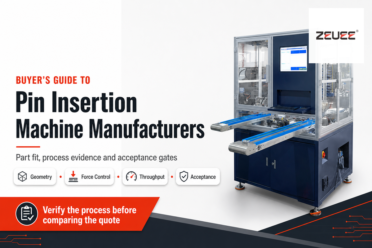
Pin insertion machine manufacturers are companies that prove a stable process for your pin, housing or printed circuit board, not companies that lead with the fastest number on a brochure. Evidence-based comparisons consider part geometry, feeding, insertion, inspection, changeover, line interfaces, and acceptance criteria.
The short answer
Shortlist suppliers only after they evaluate your representative samples and develop measurable acceptance criteria based on your requirements. Evaluate the proposed process and the evidence package; don’t concern yourself with unsupportable cycle-rate claims.
Search results for this phrase are dominated by product and service pages, so this guide does not rank manufacturers; it qualifies them across printed circuit board, connector-housing and mechanical pin-insertion applications, while the machine guide owns operating basics and the twist-pin comparison owns named vendors in that narrower category. This provides a reproducible way for procurement and engineering teams to qualify prospects while keeping the commercial decision tied to their actual application.
What a Pin Insertion Machine Actually Controls
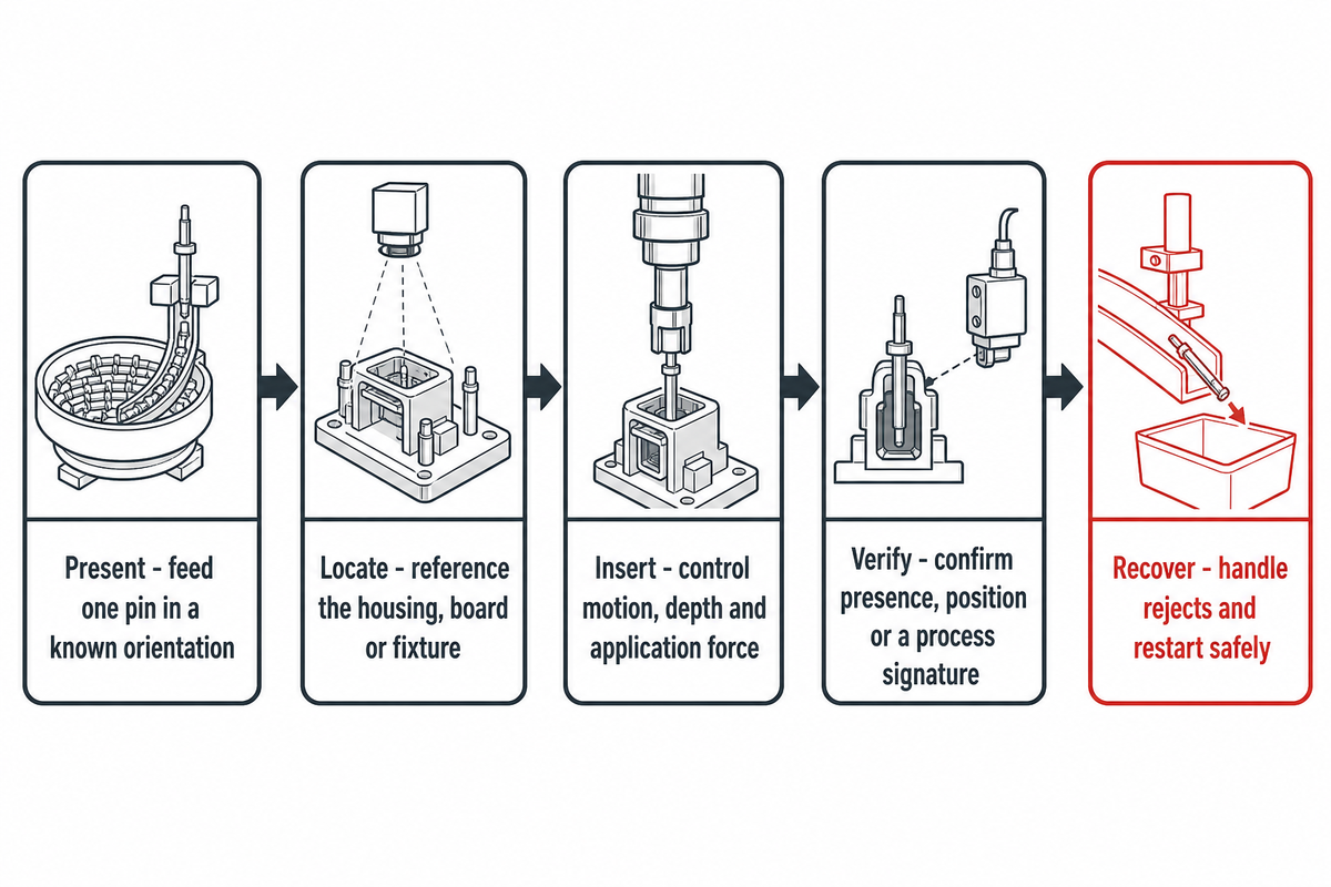
More than just pushing a part into a hole, the overall process of a pin insertion machine presents the pin, controls orientation, locates the receiving component, inserts, and verifies the result while managing exceptions and documenting the disposition of failed parts.
1. Present
Feed one pin in a known orientation.
Feed one pin in a known orientation.
2. Locate
Reference the housing, board or fixture.
Reference the housing, board or fixture.
3. Insert
Control motion, depth and application force.
Control motion, depth and application force.
4. Verify
Confirm presence, position or a process signature.
Confirm presence, position or a process signature.
5. Recover
Handle rejects and restart safely.
Handle rejects and restart safely.
This process is important because different machines verify different things. Feed-transfer sensing can verify that a pin reached the tooling, while position sensing can verify stroke or depth. Neither proves that the finished electrical connection satisfies all product specifications.
The first-party ZEUEE pin insertion configuration boundary shows one connector-insertion route. Separately, TE describes connector stitching, product-specific tooling and optional insertion-force monitoring, while Visumatic describes feed confirmation, punch-position sensing and custom tooling interfaces. These are examples of available architectures, not confirmation that every model offers these features.
Match the Machine to Pin, Substrate, and Connector Geometry
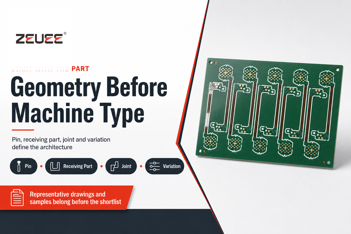
The selection of a particular machine should be based on specific components rather than a generic type of machine. Feeding and insertion are influenced by cross-section, pin length and insertion-force requirements, straightness and surface condition of pins, packaging, and pitch and geometry of retention.
| Input | What to provide | What it changes |
|---|---|---|
| Pin | Drawing, material, finish, allowed deformation, packaging | Feeder, gripper, tooling and force window |
| Receiving part | Housing or board drawing, datum scheme, hole/cavity condition | Fixture, alignment, vision and support strategy |
| Joint | Target depth, protrusion, retention and inspection rules | Motion profile, monitoring and acceptance method |
| Variation | Part families, change frequency and mixed-model sequence | Recipe control, change parts and poka-yoke |
Connector-housing insertion, plated-through-hole insertion and mechanical fastening may share the same search phrase but require different proof. Manufacturers that excel with large mechanical dowels are not automatically qualified for delicate electrical contacts, and a printed circuit board platform may not support the fixture or inspection method needed for a molded housing.
Red flag: the supplier quotes from a photograph and nominal pin diameter without requesting drawings, tolerance limits, packaged samples or the receiving-part condition.
Compare Automation Architecture, Throughput, and Changeover
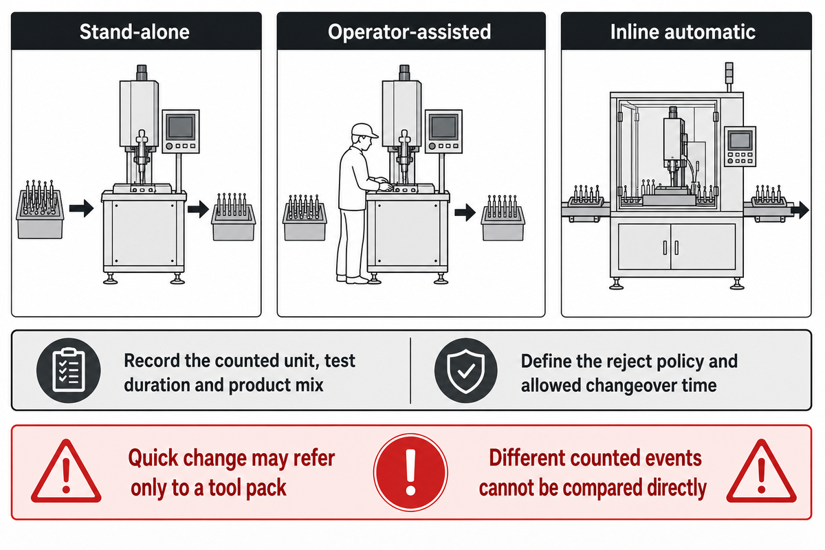
Different constraints call for different solutions, with customized solutions described through a written scope. The kind of system chosen, whether stand-alone, operator-assisted or inline, depends on whether the output is high or low, the content of labor, the interfaces upstream or downstream, the mix of products, the space on the floor, the ability to maintain the system, and the cost of a bad insertion; a fully automated assembly line, an automated assembly cell, a scalable robotic cell, a compact footprint and high-mix changeovers belong in separate scope fields.
An automatic pin insertion machine may use a modular feeder, terminal tooling, or have an interface with a robot, but calling it high-speed, high-volume, or automotive isn’t a criterion for acceptance; a pin inserting machine for press-fit PCB work may instead use a servo insertion head, an insertion force monitoring system, or tooling clearance around solder features in high-density layouts. For each of those claims, define a measurable condition that you’ll use to compare, including high speed pin insertion, high-precision motion, continuous feeding and production efficiency.
| Architecture | Useful when | Evidence to request |
|---|---|---|
| Stand-alone | The process can be decoupled and material is moved in batches. | Operator work content, buffer rules and part identification |
| Operator-assisted | Human dexterity still adds value but feeding or insertion causes strain or variation. | Ergonomic assessment, interlocks and repeatability across operators |
| Inline automatic | Volume and process stability justify integration with other stations. | Handshake states, reject routing, recovery time and line-level test |
Cycle rate shouldn’t be assumed as a unit of measurement unless assumptions on both sides are the same, and its quality control and downtime boundary must be recorded. Find out what the number of cycles actually means, if it means actuator strokes, pins presented, accepted assemblies, a short demonstration run, and clarify in the quote what the part mix is, what the inspection and replenishment is, what the planned stops are, and what happens to the rejects.
For example, TE’s public page shows one platform at up to 3.3 cycles per second and another at more than 5 strokes per second on a 30 mm pitch. These figures can’t be directly compared because the counted event, machine, tooling and application boundary are different. These figures are included here just to highlight why units and test conditions need to travel with every number.
Changeover deserves its own test because “quick change” can refer only to a tool pack. The changeover test should include selecting a recipe, changing physical parts, adjusting the feeder, confirming the fixture, first-piece inspection, and the time necessary to return to stable accepted output.
Throughput Boundary Sheet
Next to each output value, record the counted unit, test duration, product mix, operator tasks, inspection performed, reject policy, assumed level of inventory, changeover time allowed, and scope of the allowable change.
The Pin Insertion Manufacturer Application-to-Acceptance Dossier
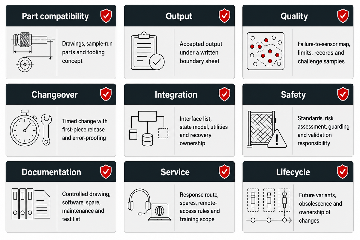
Suppliers that can be trusted will be able to explain how a requirement moves to a design and how the design will be validated. Brochures describe a platform; drawings, sample trials, measurement records and acceptance criteria define the fit for your requirement.
| Evidence category | Weak evidence | Useful evidence |
|---|---|---|
| Part compatibility | “Suitable for many pins” | Reviewed drawings, sample-run parts and tooling concept |
| Output | A maximum speed without conditions | Accepted output under a written boundary sheet |
| Quality | A sensor list | Failure-to-sensor map, limits, records and challenge samples |
| Changeover | “Fast” or “tool-less” | Timed change with first-piece release and error-proofing |
| Integration | “Ready for your line” | Interface list, state model, utilities and recovery ownership |
| Safety | A generic compliance logo | Applicable standards, risk assessment, guarding concept and validation responsibility |
| Documentation | “Manual included” | Controlled drawing, software, spare, maintenance and test-document list |
| Service | “Global support” | Named response route, spare-parts list, remote access rules and training scope |
| Lifecycle | A warranty period alone | Future-variant process, obsolescence path and ownership of changes |
Score the evidence based on the statement, demonstration, measurement or acceptance criteria. A statement can be included in the evaluation, a demonstration can narrow the focus, a measured sample can support the decision, and a signed acceptance criterion can protect the purchase.
A long list of patents or famous customer logo isn’t sufficient to justify points awarded. Quality System Certificates and other similar documentation may suggest something, but without specific application data, these won’t help define your acceptance criteria for a pin and a housing.
Define Quality, Traceability, and Acceptance Before Ordering
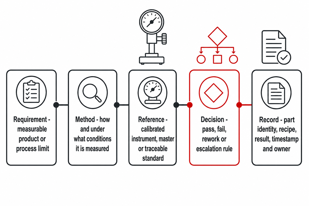
Acceptance criteria should be designed before the purchase order. This addresses sensor types, data structure, sampling, and time it takes to perform tests. If “good insertion” is specified after a machine is built, both the buyer and manufacturer can pass their test and still disagree.
Acceptance Evidence Chain
- Requirement: the measurable product or process limit.
- Method: how the characteristic is measured and under what conditions.
- Reference: the calibrated instrument, master or traceable standard.
- Decision: pass, fail, rework or escalation rule.
- Record: part identity, recipe, result, timestamp and responsible owner.
NIST’s metrological traceability guidance explains the need for an unbroken calibration chain to specified references. In practical procurement terms, ask what was measured, with which instrument, against which limit and how the record can be tied back to the production lot or part.
Safety evidence also depends on the final configuration and jurisdiction. ISO 10218-2:2025 covers industrial robot applications and cells, while ISO 12100 supplies general risk-assessment and risk-reduction principles; neither citation proves compliance for a proposed machine.
Build a Practical RFQ for Connector Assembly
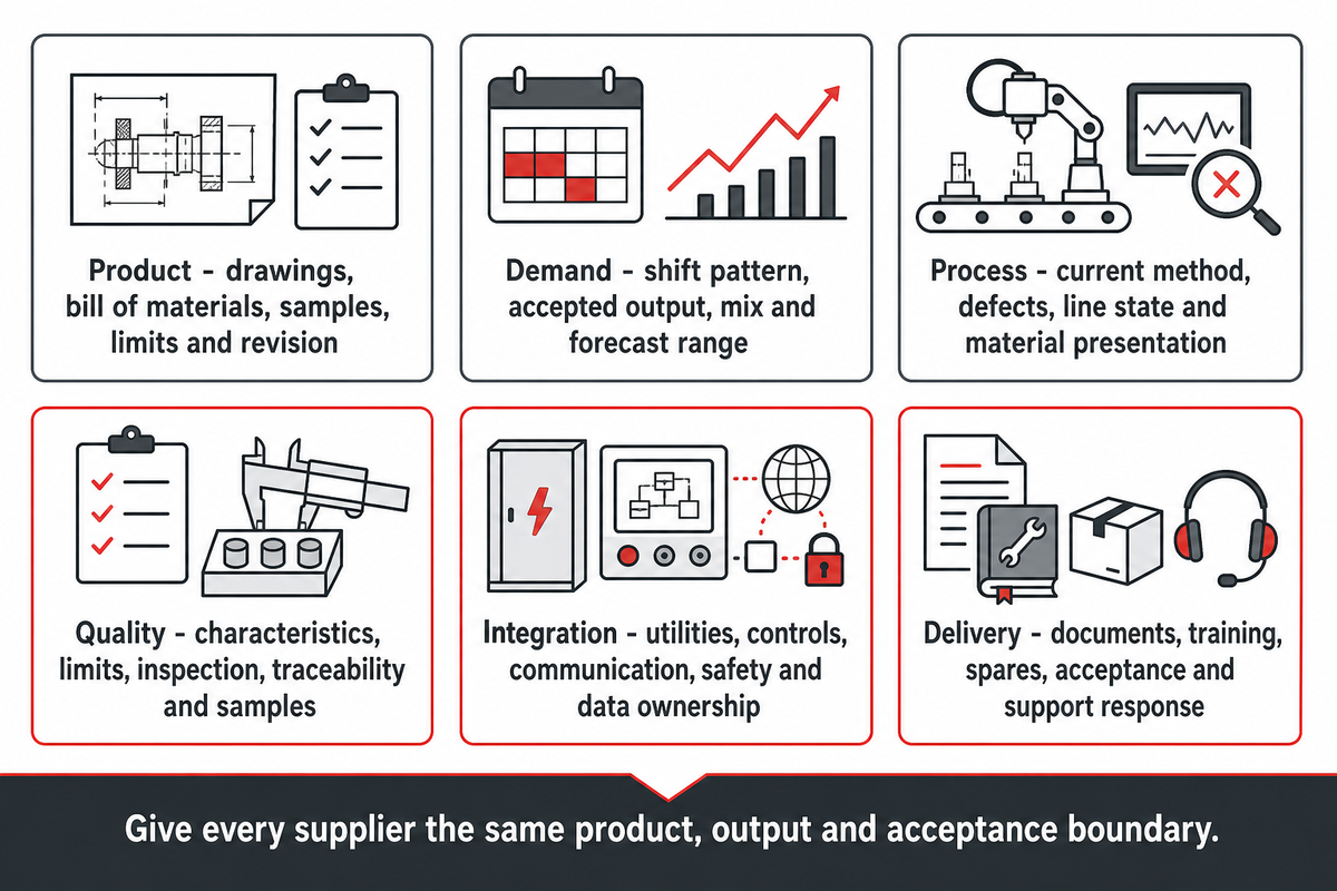
Useful requests for quotation for robot integration systems or pin insertion cells reduce or eliminate the degree of interpretation. They give every supplier the same product and output and acceptance criteria so that differences in scope become apparent before prices are compared.
| Block | Include |
|---|---|
| Product | Controlled drawings, bill of materials, samples, cosmetic limits and revision status |
| Demand | Shift pattern, target accepted output, mix and forecast range |
| Process | Current method, known defects, upstream/downstream state and material presentation |
| Quality | Critical characteristics, limits, inspection method, traceability and sample plan |
| Integration | Utilities, controls, communication, safety boundary, floor plan and data ownership |
| Delivery | Documentation, training, spares, factory/site acceptance and support response |
Ask the suppliers to state their assumptions and exclusions along with their provided scope. A low bid may exclude various components such as feeders, fixtures, inspection, line integration, overseas commissioning, as well as validation of production, that other suppliers include.
Also, state who’s responsible for obtaining samples and for design revisions. A machine that’s validated on one early sample will likely become a different project if the plating of the pins, the resin of the housing, the cavity geometry or the packaging is changed prior to installation.
Cost Signals Without Inventing a Universal Price
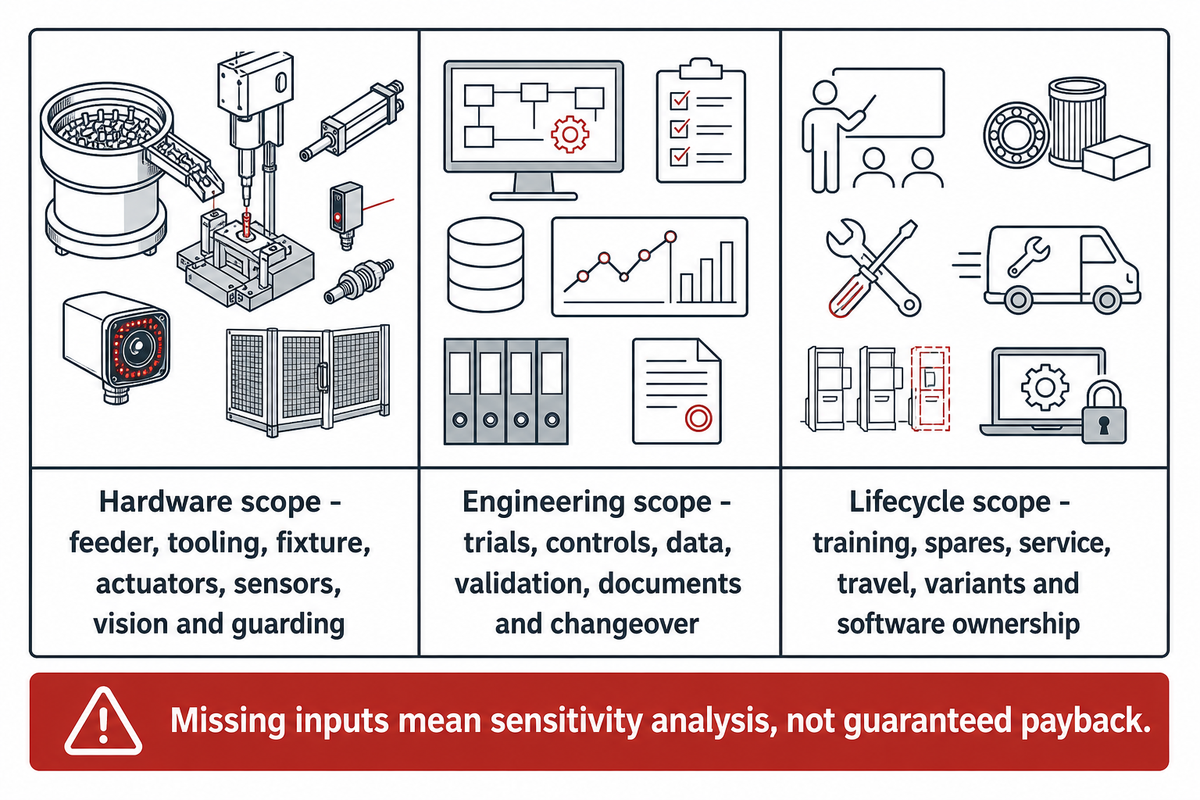
There’s no reasonable basis for a uniform price for a custom pin insertion system, as the cost is commensurate with the scope. Complexity of feeding, number of product families, proposed fixtures, motion axes, inspection, traceability, guarding, line integration, documentation, site work, and spare tools can all impact the overall solution.
Hardware scope
Feeder, tooling, fixture, actuators, sensors, vision and guarding.
Engineering scope
Part trials, controls, data, validation, documentation and changeover design.
Lifecycle scope
Training, spares, service, travel, future variants and software ownership.
Rather than comparing prices, consider the overall accepted scope. Include in the same contract optional items, exclusions, licenses, consumable tooling, travel, and future change parts.
To develop a return-on-investment (ROI) model, you’ll need to input your accepted output rate, loaded labor cost, defects and rework data, planned utilization, maintenance allowance and changeover loss. If any of these inputs is lacking, treat this as a sensitivity range analysis instead of providing a guaranteed payback time.
Cost red flag: a supplier gives a payback period before documenting the baseline process, accepted-output definition and included scope.
Where ZEUEE Fits a Connector Automation Project
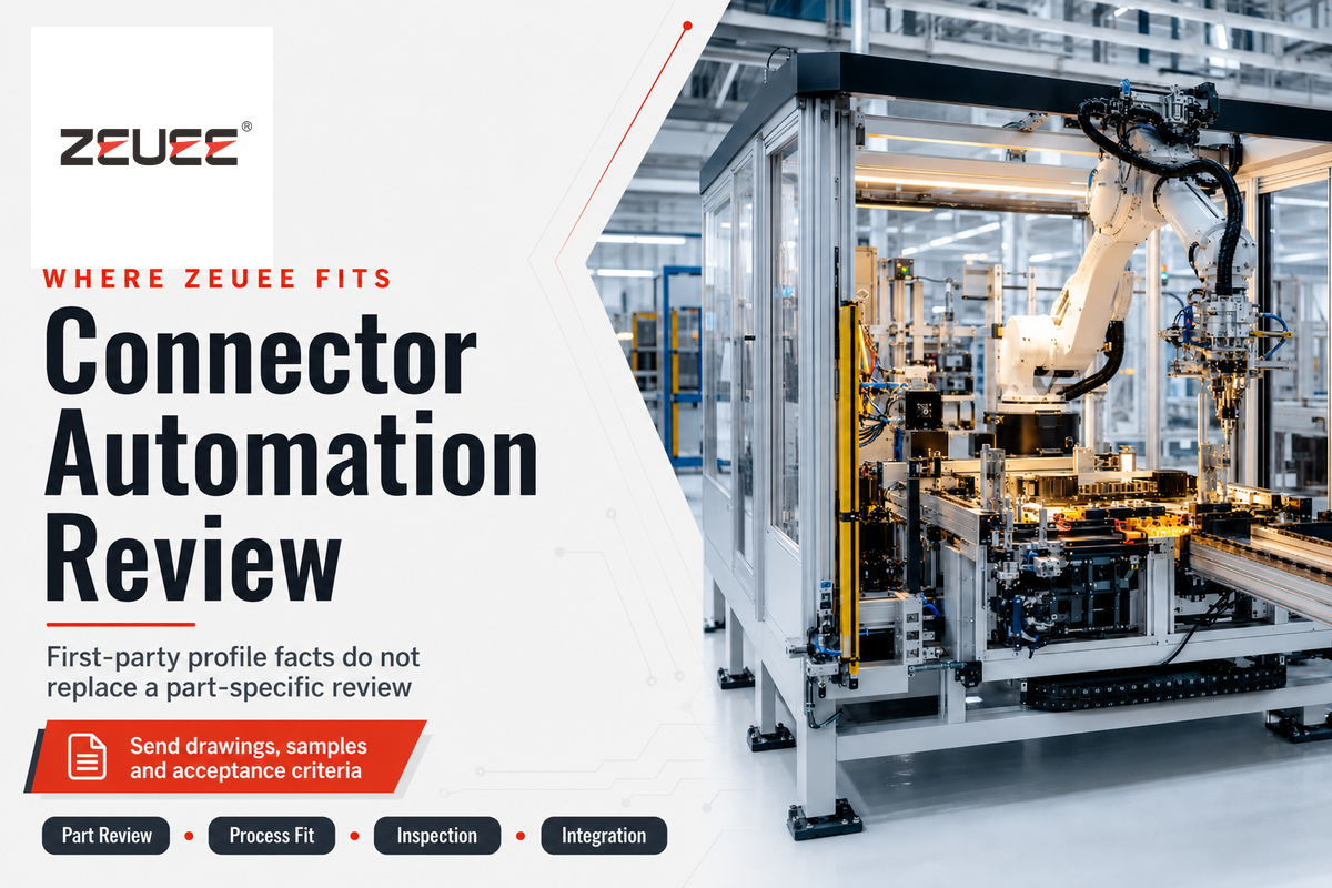
ZEUEE is the publisher of this guide and a prospective supplier, so company information should be read as first-party evidence. Shenzhen Zeyu Intelligent Industrial Science Technology Co., Ltd. states that it was founded in 2005 and designs, produces and sells industrial automation equipment.
ZEUEE company-profile facts
- 20,000-square-meter production base in Taihe, Jiangxi
- More than 120 employees
- More than 150 R&D patents stated in its profile
- ISO 9001:2015 certification stated in its company profile
- Customers in more than 30 countries and regions, as stated in its company profile.
- Custom whole-factory automation focus
These facts indicate organizational scale and automation experience, but they don’t replace a part-specific engineering review. In the next step, ZEUEE will be provided with your drawings, samples, output boundary, inspection requirements and integration conditions to assess the proposed process along with the same evidence matrix used for other suppliers.
For the commercial product route, review the first-party available insertion machine variants for your part drawing, or send your application brief with the pin drawing, housing tolerance and target output to discuss fit. Product-specific values and configuration claims should be checked on that page and in the project quotation.
The 5-Gate Manufacturer Selection Framework
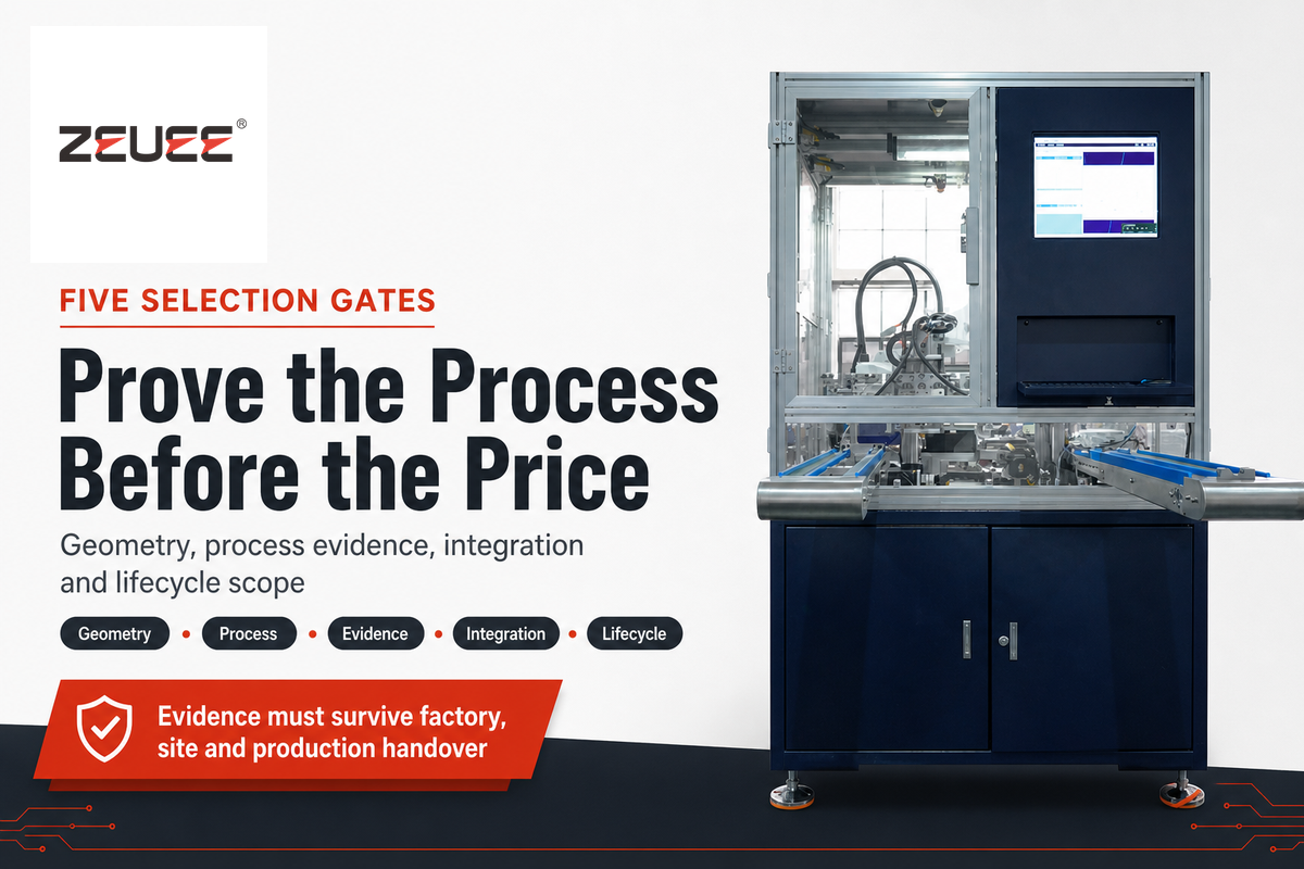
Use five gates in sequence. Suppliers that fail an early gate shouldn’t be rescued by a low price or a polished factory video.
- 1Geometry gate: Has the supplier reviewed controlled drawings and representative samples?
- 2Process gate: Does the concept cover feeding, locating, insertion, verification and recovery?
- 3 Evidence gate: Are output, quality and changeover claims tied to measurable conditions?
- 4 Integration gate: Are utilities, interfaces, safety, data, documentation and ownership defined?
- 5 Lifecycle gate: Are training, spares, support response and future variants commercially clear?
The best candidate isn’t necessarily the most automated. The best candidate is the one whose scope addresses critical risks with evidence your team can reproduce at factory acceptance, site acceptance and production handover.
FAQ: Pin Insertion Machine Manufacturers
WHY WE WRITE THIS
About ZEUEE Engineering Insights
ZEUEE shares technical guides based on real automation project experience. Since 2005, we have designed and manufactured non-standard automation equipment for connector assembly, wire harness production, robotic lines, vision inspection, and smart factory upgrades.
Founded in 2005
20,000 m² production base
120+ specialists
150+ R&D patents
ISO9001:2015 certified