Get in touch with Zeyu lntelligent Industrial Company

Rectangular Connector Machine: Engineering Guide to 5-Stage Multi-Row Contact Assembly, Inspection, and Line Sizing

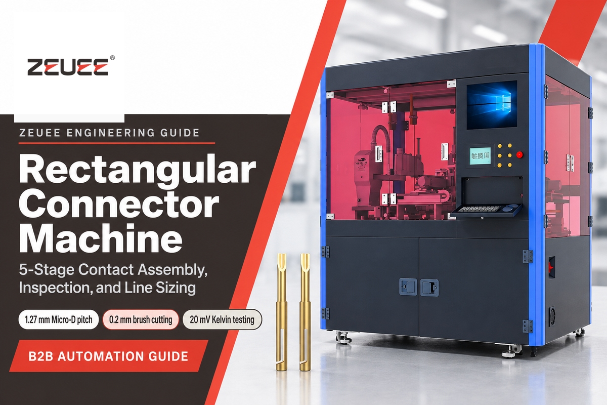
A Rectangular Connector Machine is an automated system to assemble contacts in multi-row insulator housings. This system performs functions including feeding contacts, inserting pins, four-point sleeve crimping, 0.2 mm brush cutting, closing insulator shells, and doing inline testing. Unlike benchtop ribbon presses, industrial lines match the mechanics of the different stations to the contact geometry and pitch.
Across Aerospace, Defense, Automotive and other industries, multi-row rectangular interconnects pack dozens of cavities into polarized shells. High-reliability electronic control units depend on such interfaces to route power and signals. Automating these assemblies requires tight control over sleeve concentricity, insertion depth, bristle geometry, and millivolt contact resistance. This guide explains the five-stage process window, contact physics, station sizing math, and qualification standards.
By Cherry · Updated November 2026
Quick Specs: Engineering Boundaries of Rectangular Connector Automation
- Core process sequence: Pin insertion, four-point sleeve crimping, 0.2 mm brush cutting, servo closing, and full-cavity separation-force inspection.
- Supported contact pitches: 1.27 mm (0.050-inch) MIL-DTL-83513 Micro-D, 1.78 mm × 1.52 mm HDB3 grids, standard D-Sub, and heavy-duty inserts.
- Inline verification stack: EIA-364-37 engagement and separation force gauging, telecentric 2D/3D CCD vision, and EIA-364-23 dry-circuit (20 mV, 100 mA) Kelvin testing.
- Commercial equipment scope: Project-specific machine configurations are engineered on our ZEUEE 5-machine rectangular connector assembly solutions page.
How Does a Rectangular Connector Machine Automate the 5-Stage Assembly Sequence?
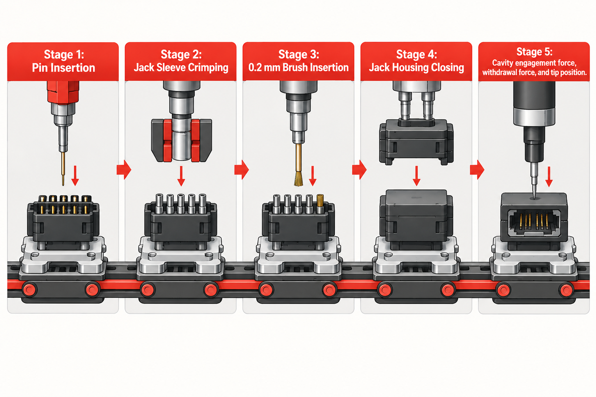
A Rectangular Connector Machine automatically assembles contacts by breaking up the process in five synchronized stations: pin insertion, four-point sleeve crimping, 0.2 mm brush cutting, servo closing and full cavity separation-force testing. Each of these stations tightly controls geometric tolerances so that the closing of the shell doesn’t deform the pin.
In general electrical engineering, interconnects can be broken into three structural families: circular connectors, rectangular connectors, and board-level interfaces. Rectangular connectors mount contacts in structured rows and columns in polarized plastic insulators or metal shells. That rectilinear grid maximizes pin density within rack-and-panel assemblies, avionics boxes, and industrial control cabinets.
Because multi-row cavities are spaced millimeters apart, manual assembly is prone to severe operator fatigue and cross-wiring. Assembly Magazine’s report on guided military connector assembly details the challenges of populating 128 sockets in a 3-inch shell. AirBorn deployed 17 fiber-optic Light Director units across two assembly lines with 25 assemblers and planned 76 more units to reduce errors. Boeing employees similarly use laser-guided machines to insert wires into connectors and build 200-wire branches. We use automation to replace human cavity hunting. Our automated connector assembly machine portfolio covers a wide variety of applications.
| Stage & Station Module | Feeding & Motion Mechanism | Critical Process Variable | Downstream Defect Prevented | Inline Verification Gate |
|---|---|---|---|---|
| Stage 1: Pin Insertion | Vibratory bowl, linear track, and PPU manipulator | Multi-row X-Y pitch indexing and axial seating depth | Shaved cavity walls, bent tails, or recessed pins | Fiber-optic presence sensor and servo force window |
| Stage 2: Jack Sleeve Crimping | Aluminum tray, linear manipulator, and 4-point cam head | Synchronous radial indent depth and sleeve concentricity | 2-die barrel ovality and flash that jam cavities | Cam stroke monitoring and concentricity check |
| Stage 3: 0.2 mm Brush Insertion | Servo wire drive, rotary bevel cutter, and hollow rotary table | Wire bundle length and bevel-cut tip angle on 0.2 mm wires | Flat-sheared wire burrs that splay bristles during mating | Dual-seat rotary interlock and optical tip check |
| Stage 4: Jack Housing Closing | Servo press ram with 3-axis compliant fixture alignment | Programmable closure depth and latch preload force curve | Cracked latches, pinched seals, or incomplete seating | Linear encoder depth check and peak force cap |
| Stage 5: Separation-Force & Vision QC | Calibrated test-pin array, load cell, and telecentric CCD camera | Cavity engagement force, withdrawal force, and tip position | Under-tensioned socket sleeves, missing pins, or open joints | Automated OK/NG sorting chute with force logging |
With the 5-Station Rectangular Contact-to-Housing Process Window, engineers can keep stations connected. Upstream stations can affect downstream stations, for example if station 2 introduces barrel ovality on a jack sleeve, closure in station 4 will spike in force. Stage 5 extraction testing will then reject the finished housing.
As discussed in Connector Supplier’s report on connector assembly equipment, a complete fabrication process includes preparing wire, inserting contacts, crimping and marking. In a five-machine rectangular line, each station logs a pass/fail state to the pallet controller. This ensures that no unverified contact gets through to the closure step.
Why Do Multi-Row Insulator Housings Require Synchronized Five-Station Indexing?
Multi-row insulator housings require synchronized five-station indexing because several error sources, including pitch errors, crimp ovality, and seating drift, can accelerate and combine in consecutive rows. When an insulator holds two to eight staggered rows, a 0.05 mm offset at pin insertion compounds rapidly. Cumulative tolerance stack-up rapidly creates binding conditions at the final closure of the housing.
Synchronized indexing provides a single datum reference to the insulator carrier pallet from Stage 1 through Stage 5. Each station reads the upstream pass/fail status before cycling. Any defective sub-assemblies are ejected prior to the final closure of the housing. This early ejection prevents gold-plated contacts and insulators from becoming scrap.
How Do Crimp Contacts, 0.2 mm Brush Bundles, IDC, and Press-Fit Pins Compare?
Crimp contacts, 0.2 mm brush bundles, insulation displacement terminations (IDTs), and press-fit pins differ in mating force, tooling, and survival of vibration. Brush bundles cut mating force significantly as compared to standard pin-and-socket contacts. Additionally, screw-machined crimp sleeves carry higher continuous current as compared to stamped open-barrel terminals.
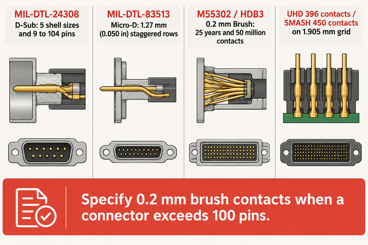
Engineers must distinguish separable mating interfaces from permanent wire or board terminations before specifying automation. Amphenol’s military rectangular connector specifications document how M55302 B3 and HDB3 contacts use intermeshing 0.2 mm wire bundles. These low-mating-force brush contacts have served for over 25 years with more than 50 million contacts fielded. Flight and defense qualifications include the M1A2 Abrams, F-16 Falcon, F/A-22 Raptor, F-35 Lightning II, and AIM-132 ASRAAM.
Standard rack-and-panel D-Subminiature connectors covered by MIL-DTL-24308 specify 5 shell sizes and 9 to 104 pins. Ultra-high-density rectangular connectors push the limits even further. Amphenol SIAL inserts contact families from 18 to 392 contacts in 5 rows. UHD packages 396 contacts at 80 contacts per linear inch, while SMASH reaches 450 contacts on a 1.905 mm grid.
| Architecture Family | Typical Pitch / Grid | Contact Mating Force | Primary Station Tooling Required | Dominant Field Failure Mode |
|---|---|---|---|---|
| MIL-DTL-24308 D-Sub (Machined) | 2.74 mm–2.77 mm (5 shell sizes, 9–104 pins) | Standard machined pin-and-socket engagement | Aluminum tray feeder + 4-point cam crimp + PPU insertion | Bent retention lances from off-axis insertion |
| MIL-DTL-83513 Micro-D | 1.27 mm (0.050 in) staggered rows | Compact twist-pin spring engagement | High-precision X-Y servo table + telecentric CCD vision | Cavity wall shaving at sub-millimeter pitch |
| M55302 / HDB3 0.2 mm Brush | 1.78 mm × 1.52 mm (0.070 in × 0.060 in) | Fractional-newton low mating force bundle | Servo wire feed + rotary bevel cutter + hollow rotary riveting | Bristle splaying from flat guillotine shearing |
| Heavy-Duty Rectangular (Han 6B, 48B) | 6–48 poles + PE (16 A / 500 V) | High-normal-force industrial power socket | Linear pallet transfer + heavy crimp + torque-controlled closure | Insert push-back under axial load |
| UHD / SMASH High-Density Signal | 1.905 mm chevron or 8-row grid (up to 450 pins) | Low-force hyperboloid or signal engagement | Multi-axis servo PPU + automated separation-force QC | Cumulative mating load exceeding shell latch rating |
| Ribbon IDC Rectangular Header | 0.8 mm–2.54 mm wire-to-board (30 to 20 AWG) | Permanent insulation displacement slot | Dedicated vertical mass-termination press module | Incomplete insulation slicing on fine conductors |
| PCB Compliant Press-Fit Header | 2.0 mm–2.54 mm multi-row backplane | Eye-of-needle radial board retention | Continuous carrier-strip stitcher + servo force-distance ram | Plated through-hole barrel deformation |
| ARINC 600 Avionics Rack & Panel | Multi-insert modular shell | Low-insertion-force avionics contact system | Modular 5-machine cell + 3-axis floating blind-mate head | Guide-pin binding from 2-axis bushing gravity sag |
| Hybrid Power + Signal Rectangular | Mixed 16 A power poles and signal rows | Dual-window engagement (power vs signal) | Dual-track feeding + recipe-switched servo closure | First-mate/last-break PE contact sequence error |
Wide catalog scope reveals why single-purpose cam tooling is inadequate across product lines. Distributor catalogs index over 365,000 rectangular headers and housings with 0.3 mm to 11 mm pitches and 1 to 14 rows. Having the right feeder mechanics for the exact contact family prevents costly machine retrofits during commissioning.
When Should Engineers Specify 0.2 mm Brush Contacts Over Pin-and-Socket Terminations?
Specify 0.2 mm brush-wire bundle contacts when a rectangular connector exceeds 100 pins or is subject to severe vibration. These contacts are ideal for blind-mated avionics trays. Because multiple 0.2 mm wires wipe past each other laterally, mating force decreases significantly, and redundant current paths are maintained.
Most pin-and-socket contacts use a single cantilever spring beam that pushes against a rigid pin. In high-pin-count housings, pin-and-socket insertion forces across many cavities add up to a high mating load. That high load can crack the housing and/or damage other components. By using brush bundles, each contact engages at a fraction of a newton, preventing bowing and fretting.
How Do Pin Insertion Stations Control Pitch Accuracy, Depth, and Retention Force?
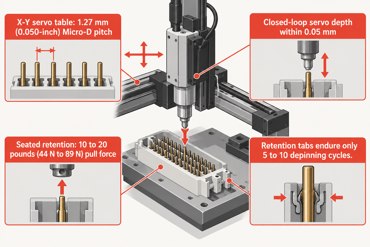
A connector uses a linear servo-actuator or vibratory feeder to insert pins with precision into pin-insertion stations that also control seat depth. Closed-loop load-cell monitoring verifies every pin stroke. Some pin insertion stations can also employ closed-loop controls to adjust and verify retention forces. The feeds and servo systems are designed to accommodate the various geometries of pins, including right angle pins and turned contacts.
The type of feeding geometry used determines the architecture of the stations. In standard board headers, stitching pins are typically taken directly from a continuous stamped carrier strip. In the aerospace and industrial rectangular connectors parts, stitching pins, right angle bent tails, and turned contacts are often mixed and fed from deep housings. For these parts, our servo-controlled connector pin insertion systems feed pins through a vibratory bowl and linear track.
Before the pick-and-place unit (PPU) grasps a pin, fiber-optic sensors verify tip presence and tail orientation on the rail. The X-Y servo table indexes the insulator housing across staggered rows down to a 1.27 mm (0.050-inch) Micro-D pitch. Closed-loop servo pressing controls axial insertion depth within 0.05 mm.
Field failure data shows why insertion angle and seating depth can’t rely on open-loop pneumatic cylinders. According to Tonful’s terminal retention and extraction analysis, properly seated terminals withstand 10 to 20 pounds (44 N to 89 N) of pull force. Off-axis insertion bends primary retention lances, scratches pin cavities, and cracks insulator walls. In addition, retention tabs endure only 5 to 10 depinning cycles before weakening, making first-time seating accuracy critical.
The PPU insertion head must insert the longest top row pin tails first or follow a row sequence. Programmable servo Z-strokes allow the PPU to adjust the insertion height row by row to insert multi-row tails. This stepped insertion prevents the gripper fingers from colliding with already seated, right-angle tails.
Why Does Four-Indent Jack Sleeve Crimping Outperform Open-Barrel Stamping on Machined Contacts?
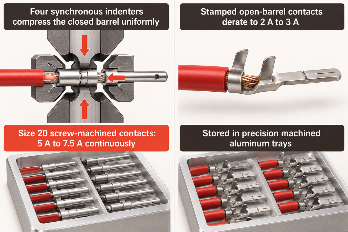
Four-indent jack sleeve crimping outperforms two-die open barrel stamping on machined contacts because four synchronous indenters compress the closed barrel uniformly. This creates radial symmetry, which results in a clean, jam free fit through multi-row cavities.
When crimping an electrical connector for high-reliability rectangular assemblies, engineers differentiate between open-barrel terminals and closed-barrel machined contacts. Practitioner engineering analyses of D-Sub contact ratings note that size 20 screw-machined contacts carry 5 A to 7.5 A continuously. By contrast, stamped-and-formed open-barrel contacts derate to 2 A to 3 A. Closed-barrel contacts achieve higher conductivity by compressing solid copper walls under SAE AS22520 four-indent aerospace crimping standards.
Delicate thin-walled jack sleeves can’t tolerate bulk vibratory bowl tumbling. Continuous recirculation dents sleeve rims and scuffs gold plating. Instead, four-point cam connector crimping machines store sleeves in precision machined aluminum trays. A linear manipulator transfers each sleeve cleanly into a cam-driven four-indent crimping head.
Synchronous cam indenting, as documented in FPI’s engineering study on connector contact force reliability, holds the contact spring normal force within the elastic window. Moving the contact normal force beyond this window results in five failure modes.
Counter-Intuitive Engineering Rule, More Crimp or Closure Force Is Not Always Better: Compressing a jack sleeve beyond its elastic limit or over-preloading a housing latch drives the copper conductor spring beyond its elastic limit. Once permanent set is introduced, elevated operating temperatures accelerate stress relaxation. Contact resistance then drifts upward in service.
Brush-Wire Bevel Cutting and Servo Jack Closing: Controlling Sub-Millimeter Contact Seating
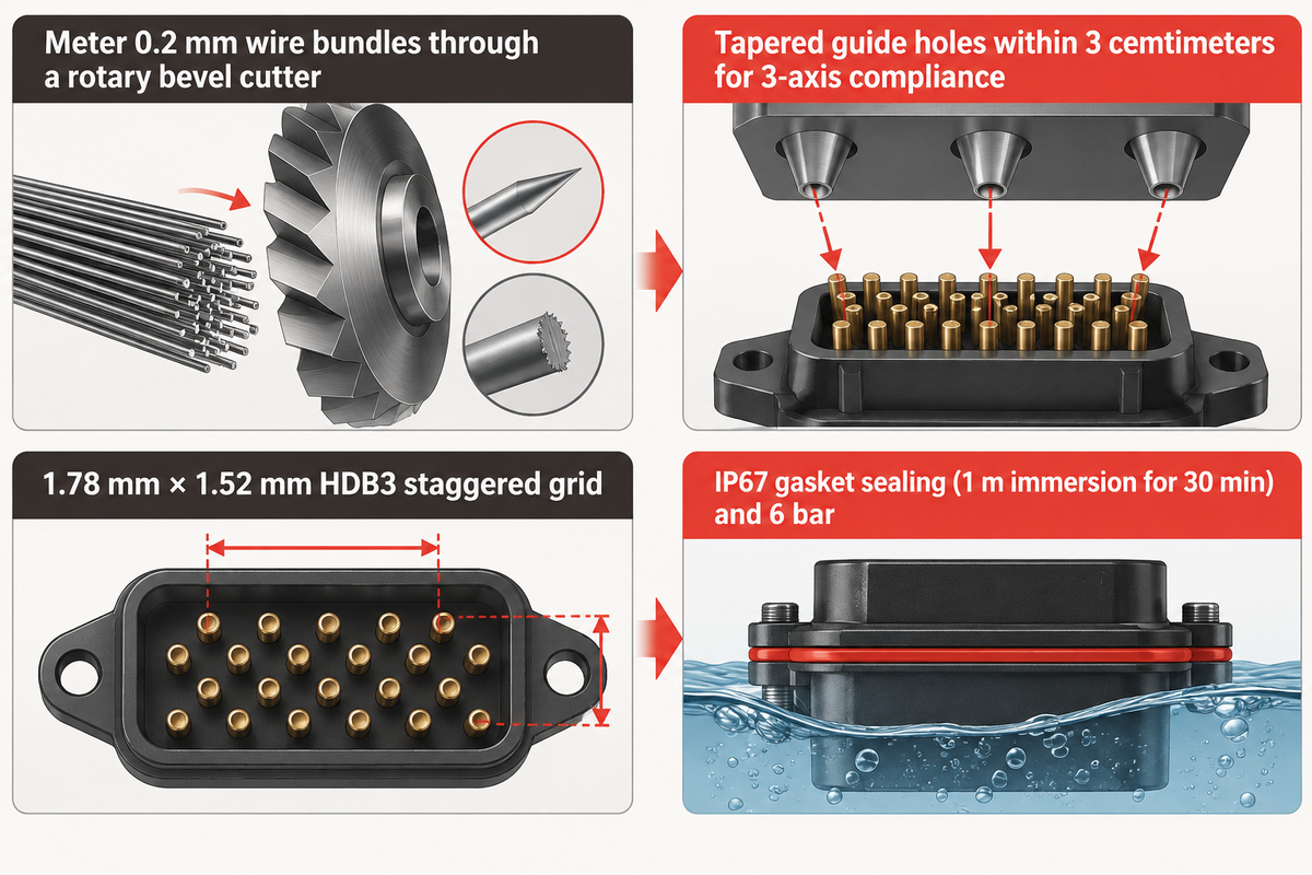
Sub-millimeter seating is achieved through brush-wire insertion and servo jack closing stations that meter 0.2 mm wire bundles through a rotary bevel cutter. A hollow rotary platform then aligns the riveting process. A servo press closes the shell. Bevel cutting creates a wire tip that’s tapered. Latch crushing is prevented through servo rams.
In a twin-row brush-type rectangular connector, each contact seat contains a bundle of 0.2 mm high-tensile wires. Servo feed rollers meter the wire to the exact length with sub-millimeter repeatability. A rotary bevel-cutting head then shears the wire at an acute angle. A hollow rotary indexing platform then aligns contact loading and cam crimping as well as the riveting process across dual-row terminal seats in a compact footprint.
Once all contacts and inserts are placed, sub-assemblies are routed to automated connector housing closure stations. For multi-row housings, it’s important to align the plug shell, insulator inserts, and the rear retainer. Conventional two-axis (X-Y) floating bushings often fail when fixtures sit vertically or experience axial module length tolerances.
Honeywell’s US Patent Application US20020081881A1 (granted as US6592387B2) analyzed the same blind-mating failure on 9-pin, 15-pin, and 25-pin rectangular D-Sub connectors. In Honeywell’s design, mounting plate 502 connects to main rear plate 504 via shoulder bolt 506. Locating tapered guide holes within 3 centimeters of the connector provides three-axis (X, Y, and Z) compliance during automated closure.
Heavy-duty industrial rectangular housings demand similar axial alignment discipline during closure. In Verchil’s industrial rectangular connector guide, over-tightening shell screws cracks housings, while under-tightening compromises IP67 gasket sealing (rated for 1 m immersion for 30 min) and 6 bar pneumatic modules. Servo closure rams reduce operator variability by enforcing a digital force-displacement window.
Why Does Rotary Bevel Cutting Prevent Bristle Splaying in Twin-Row Brush Connectors?
Rotary bevel cutting of the 0.2 mm wire removes flat burrs. Lateral intermeshing of bristles occurs when two bundles of brushes come in contact with each other. When two opposing brush bundles mate, tapered wire tips guide the bristles into smooth lateral intermeshing.
Flat guillotine blades flatten a 0.2 mm wire into a spade edge. Inside a tight 1.78 mm × 1.52 mm HDB3 staggered grid, a single splayed bristle can bridge adjacent cavities. When spaced like this, bristles can bridge adjacent cavities and cause an unexpected increase in the insertion-force required at Stage 5.
How Do Automated Separation-Force and CCD Vision Stations Guarantee 100% Pin Inspection?
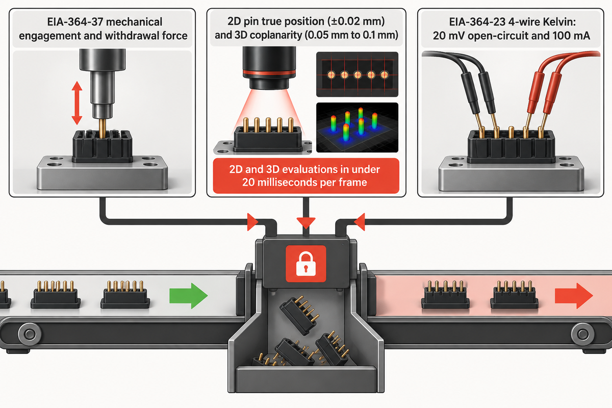
Automated separation-force and CCD vision stations guarantee full-cavity pin inspection by testing every cavity’s mechanical engagement and withdrawal force under EIA-364-37. Simultaneously, telecentric optics measure pin-tip true position within ±0.02 mm, and four-wire Kelvin probes verify dry-circuit resistance under EIA-364-23. Any assemblies that are out of spec are diverted to locked reject chutes.
A widened socket sleeve in a multi-row housing can’t be detected by sample-based manual pull testing. In Stage 5 of the 5-Station Rectangular Contact-to-Housing Process Window, gauge pins cycle into every populated cavity. Load cells measure the insertion and separation force and compare the values against upper and lower limits of the recipe. According to Assembly Magazine’s review of Cirris Pin-Sight inspection systems, a CCD camera and a retention force gauge verify rectangular connectors within a 3.5” x 3.5” area. Universal chucks also position connectors up to 3” within a 16” square area of a working envelope across more than 100 machines in the field.
For high-speed cam or servo lines, our inline telecentric CCD and separation-force inspection automation evaluates 2D pin true position (±0.02 mm) and 3D pin coplanarity (<0.05 mm to 0.1 mm). High-speed GPU processing completes both 2D and 3D evaluations in under 20 milliseconds per frame. Optical coaxial and low-angle dark-field illumination suppresses false rejects on reflective gold-plated contacts.
Electrical verification should also avoid burning away thin surface oxides. Standard 12 V or 24 V continuity testers cause arc puncture across contaminated contacts, masking latent field failures. Per EIA-364-23 low-level contact resistance (LLCR) test standards, inline four-wire Kelvin probes should limit the open-circuit voltage to 20 mV and the test current to 100 mA.
By combining 20 mV dry-circuit Kelvin probing with mechanical separation force curves, defects that vision can’t detect can be found. A camera helps verify that the pin tip is positioned to the correct X-Y coordinates. Lastly, the gauge-pin force curve and millivolt resistance check verify that the crimp barrel and the internal socket sleeve are properly coupled.
How Do Engineers Size Cam Rotary Indexing vs. Servo Linear Transfer Stations?
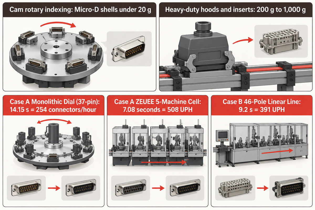
Cam rotary indexing excels at transferring lightweight Micro-D shells under 20 g. Heavy die-cast housings with large pin counts favor servo linear transfer or decoupled five-machine transfer cells.
One automation false impression is increasing rotary dial indexing speed always increases good part count output. This isn’t the case with heavy rectangular connectors, e.g., multi-component heavy-duty rectangular hoods and inserts, which weigh between 200 g to 1,000 g. For these, rotational inertia applies, where mass is multiplied by radius squared. This results in higher angular velocity and acceleration, which shakes loose pins before the trays close.
With a synchronized rotary dial, the slowest station also locks the cycle to all other stations. Plants may stitch breakaway headers rated 3A (per contact or 61-contact military inserts). They assemble 0.8mm parallel board-to-board systems with 16 PCB stack heights in 9 sizes, up to 200 positions. A single head inserter stalls downstream stations.
| Cell / Motion Configuration | Target Connector Family | Part Mass & Pin Envelope | Bottleneck & Buffer Behavior | Changeover Mode |
|---|---|---|---|---|
| 1. Cam Rotary Dial (8–12 Stations) | MIL-DTL-83513 Micro-D sub-assemblies | <20 g shell; 9–25 pins | Hard-linked index; longest station sets line takt | Dedicated nest swap + cam stroke check |
| 2. Hollow Rotary Twin-Seat Cell | 0.2 mm brush-wire twin-row inserts | 20 g–80 g; dual-row brush bundles | Compact rotary table couples wire cut, crimp, and rivet | Servo wire-length recipe + cutter blade index |
| 3. Hybrid Rotary + X-Y Servo Table | Standard MIL-DTL-24308 D-Sub (9–50 pins) | 30 g–120 g polarized metal/plastic shell | X-Y servo stitches rows while dial transfers housings | PLC pitch recipe switch within same shell family |
| 4. Synchronous Linear Indexing Chassis | Multi-row wire-to-board headers (2–4 rows) | 15 g–100 g thermoplastic housing | Straight-line access for multiple side-by-side feeders | Quick-release feeder track + software pin-skip map |
| 5. Asynchronous Servo Linear Pallet Line | Heavy-Duty Rectangular (Han 6B–48B, HEE-046) | 200 g–1,000 g+ hood and 6–48 pole insert | Queued pallets decouple slow multi-pin insertion from QC | Pallet nest insert swap + barcode recipe load |
| 6. Dual-Gantry Parallel Pin Stitching Cell | UHD / SIAL / SMASH high-density inserts (18–450 pins) | 80 g–350 g multi-row insulator block | Twin PPU heads halve sequential pin insertion dwell time | Recipe matrix recall across row/column grid |
| 7. Tray-Fed Cam Crimping Standalone Module | Machined closed-barrel jack sleeves (26–12 AWG) | Individual turned contacts in aluminum trays | Batch tray buffer isolates crimping from housing assembly | Aluminum tray plate + 4-indent turret positioner |
| 8. ZEUEE 5-Machine Decoupled Modular Cell | Full-process rectangular & brush connectors | 9–104+ pins across straight, bent, and brush types | 5 standalone machines allow parallel balancing and zero idle | Run only required stations per SKU order |
| 9. Semi-Automated Guided Cable Assembly Cell | Low-volume aerospace rack-and-panel cable assemblies | Custom multi-branch wire bundles (up to 128 sockets) | Operator insertion guided by LED/laser + Pin-Sight QC | Instant digital wiring table load |
Example Engineering Calculation: Determining Size of a 37-Pin D-Sub Cell vs. a 46-Pole Heavy-Duty Line:
Two examples illustrate the use of line sizing. Case A assembles a 37-pin D-Sub insulator at 0.35 seconds per pin plus 1.2 seconds pallet transfer. Case B assembles a 46-pole heavy-duty insert (i.e. an HEE-046-FQ 16A/500V block) at 0.45 seconds per contact plus 2.0 seconds transfer.
- In Case A on a single-head monolithic dial, pin insertion takes 37 × 0.35 s + 1.2 s = 14.15 s per housing. While jack closing finishes in 2.5 s and vision QC needs 2.0 s, the monolithic dial remains locked to 14.15 s (illustrative cycle capacity of 3,600 ÷ 14.15 = 254 connectors/hour).
- In Case A, on a ZEUEE decoupled 5-machine modular cell, pairing two parallel pin-insertion modules cuts the bottleneck rhythm to 7.08 seconds. The two inserters feed a closing module, a crimping module, and a separation-force QC module (illustrative cycle capacity of 3,600 ÷ 7.08 = 508 UPH).
- In Case B on a 46-pole heavy-duty linear pallet line, sequential single-head insertion takes 46 × 0.45 s + 2.0 s = 22.7 s. Splitting insertion across three buffered linear stations (15, 16, and 15 poles) cuts bottleneck dwell to 16 × 0.45 s + 2.0 s = 9.2 s (illustrative cycle capacity of 3,600 ÷ 9.2 = 391 UPH).
Note: These cycle times illustrate capacity math; actual output times are verified to part drawings and feeders.
Qualification Standards Governing Rectangular Connector Assembly (MIL-DTL-83513, MIL-DTL-24308, SAE AS39029, and EIA-364)
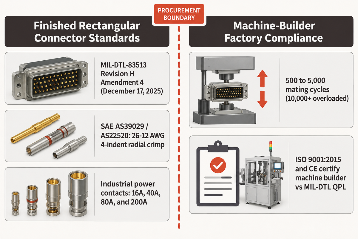
Standards for rectangular connector assembly vary by product specification, be it military, electrical, or mechanical, as well as factory quality standards. Product specs include MIL-DTL-83513, MIL-DTL-24308, and SAE AS39029, while test procedures follow EIA-364 and IEC 60512. Equipment purchasers must correlate each product test clause to an inline sensor of the machine.
Many of the military connector specifications are under active revision. According to the DLA ASSIST official record 33936 for MIL-DTL-83513, the detail specification for microminiature polarized-shell rectangular connectors is currently in Revision H Amendment 4. This amendment was issued on December 17, 2025, with the next review scheduled for December 16, 2030. Similarly, DLA ASSIST official record 33934 for MIL-DTL-24308 specifies miniature rack-and-panel connectors.
For heavy-duty industrial rectangular connectors, industrial rectangular connector compliance guidelines enforce strict mechanical and environmental limits. Standard industrial power contacts are graded at 16A, 40A, 80A, and 200A by blade or pin size. Standard industrial connectors are rated for 500 to 5,000 mating cycles, while overloaded versions reach 10,000+ cycles.
| Standard / Clause | Governed Scope | Key Quantitative Threshold | Mapped Automated Station Control |
|---|---|---|---|
| MIL-DTL-83513 (Rev H Amd 4, Dec 2025) | Microminiature polarized-shell Micro-D connectors | 1.27 mm (0.050 in) pitch contact seating and mating | X-Y servo table pitch indexing + telecentric 2D/3D CCD vision |
| MIL-DTL-24308 | Miniature rack-and-panel D-Subminiature connectors | 5 shell sizes, 9–104 pins polar shell geometry | PPU straight/bent pin insertion + servo jack housing closure |
| SAE AS39029 / AS22520 | Removable machined crimp contacts & 4-indent tooling | 26–12 AWG synchronous 4-indent radial crimp profile | Aluminum tray feeder + 4-point cam crimping station |
| MIL-DTL-55302 (B3 / HDB3) | Low-mating-force printed circuit & brush connectors | 0.2 mm intermeshing brush-wire bundle contact system | Servo brush-wire metering + rotary bevel cutter + hollow rotary |
| EIA-364-37 | Contact engagement and separation force test | Individual cavity min withdrawal & max insertion force | Stage 5 automated gauge-pin separation-force testing head |
| EIA-364-23 / IEC 60512-2-1 | Low-level contact resistance (LLCR) dry-circuit test | Max 20 mV open-circuit voltage; max 100 mA test current | 4-wire Kelvin dry-circuit resistance probe station |
| IEC 60512-15-2 (Test 15b) | Axial insert retention in rectangular housing | Zero insert push-back under specified axial load | Servo jack closing depth encoder + force-displacement window |
| IEC 60512-9-1 (Test 9a) Endurance | Heavy-duty rectangular endurance & electrical ratings | 500–5,000 standard cycles (10,000+ overloaded); 16 A / 500 V | PE ground pin length check + torque-controlled screw/latch seating |
| IPC/WHMA-A-620 | Cable and wire assembly acceptance | Zero splayed strands, proper bellmouth, and crimp height | Pre-insertion wire strip vision check + crimp force monitor |
| AIAG MSA & ISO 9001:2015 / CE | Machine measurement capability & factory quality system | Verified gauge repeatability and locked reject-chute containment | FAT gauge capability run + hardware safety interlocks |
Keep the certification boundary clear during procurement. ISO 9001:2015 and CE mark certify the machine builder’s quality management system and equipment safety. Conversely, MIL-DTL-83513 or MIL-DTL-24308 QPL status applies to the finished connector product tested in an accredited laboratory.
What Drives Rectangular Connector Machine Cost, Changeover Time, and FAT Acceptance?
Station count, feeding mode, pitch tolerances, and inline inspection gauges drive the cost of Rectangular Connector Machines and affect changeover times and Factory Acceptance Test (FAT) sign-off. A production line can use from one to five linked modules. Each unique housing geometry drives unique equipment costs and lead times. Therefore, a drawing-based quotation is required.
Prior to quoting, three mechanical cost drivers must be evaluated by custom automation builders. First, vibratory bowls and aluminum, machined sleeve trays, each designed to specific part families, must be manufactured for the contact family in question. Second, X-Y servo tables and rotary platforms, with requirements at the sub-millimeter level, dictate the use of higher-grade linear encoders compared to single-row stitchers. Third, the use of telecentric 2D/3D CCD optics and full-cavity EIA-364-37 separation-force testing creates a need for dedicated metrology hardware.
When differentiating component OEMs from automation builders, when buyers say that electrical connectors are better compared to the assembly machinery builders, TE Connectivity, Amphenol, Molex, Harting, and Smiths Interconnect are some of the catalog companies that design and manufacture finished rectangular connectors. Automated production lines to assemble those components are built by custom equipment builders.
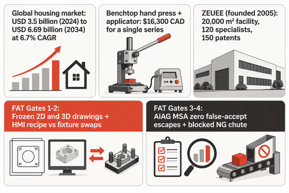
Founded in 2005, the Shenzhen Zeyu Intelligent Industrial automation engineering team (ZEUEE) operates a 20,000 m² manufacturing facility. The company employs more than 120 automation specialists and holds over 150 patents, including 32 invention and 68 utility patents, under ISO 9001:2015 and CE standards. ZEUEE builds both standalone stations and five-module rectangular connector cells.
Market growth explains why connector plants are shifting toward modular, recipe-driven machinery. According to Market.us’s Global Rectangular Connector Housing Market report, global housing revenue reached USD 3.5 billion in 2024. The market is projected to reach USD 6.69 billion by 2034 at a 6.7% CAGR. In 2024, Asia Pacific accounted for 48.3% of the total market share, while plastic housings represented 62.8% of global volume and cable-mount designs accounted for 58.5%.
When Should Connector Plants Buy Finished Connectors vs. Automating Assembly In-House?
Connector plants purchase finished connectors or pre-terminated cable assemblies if annual volumes per SKU are low and tooling costs are greater than labor costs. Automating assembly in-house becomes compelling when multi-row runs require full-cavity separation-force traceability or proprietary brush and crimp geometries. In-house lines are also warranted if a plant runs recipe changeovers frequently across shell sizes.
Even benchtop press hardware carries a steep entry threshold. Practitioner cost breakdowns for fine-pitch 0.8 mm rectangular terminations show that a single JST HPD-M2A hand press costs $3,300 CAD. Adding one H2-SUR30ED-X applicator module costs another $13,000 CAD, totaling $16,300 CAD for a single series without automated feeding. On high-volume multi-SKU lines, programmable X-Y servo pin insertion and modular five-station cells amortize across entire connector families.
FAT Acceptance & Verification Boundary Checklist:
- Drawing and sample freeze: Written quotes for custom machines require frozen 2D and 3D drawings and physical samples. Lead time and cycle guarantees for fixtures are also quoted this way.
- Recipe versus hardware changeover validation: Verify software HMI pitch-skip recall across same-datum shells (such as 9-pin to 37-pin layouts) separately from mechanical nest, PPU jaw, and aluminum tray swaps.
- Measurement system capability (AIAG MSA): Telecentric CCD vision inspection and EIA-364-37 separation-force stations should be qualified with a production-lot run demonstrating verified gauge repeatability with zero false-accept escapes.
- Reject interlock audit: Challenge the system with bent-pin, missing-pin, un-crimped sleeve, splayed brush, and other such samples and verify blocked NG chute containment.
Engineer Your Rectangular Connector Assembly Line with ZEUEE
Need a standalone 0.2 mm brush-wire bevel-cutting station, a tray-fed four-point cam crimping module, or a turnkey five-machine cell? ZEUEE configures each station around your exact insulator and contact drawings with full-cavity separation-force inspection. Explore our ZEUEE 5-machine rectangular connector assembly solutions or submit your connector housing drawings for a cycle-time evaluation.
Frequently Asked Questions
Can a single Rectangular Connector Machine run both straight pins and right-angle bent tails across multiple row counts?
Yes, when equipped with dual-track feeding or interchangeable PPU gripper jaws and a servo X-Y indexing table.
Straight pins and right-angle bent tails require distinct vibratory track profiles and pick-and-place insertion trajectories. Stepped Z-axis motion ensures each bent tail clears adjacent rows without colliding with seated terminals. Multi-row pitch offsets switch digitally through PLC recipes when the housing datum width matches. If the contact wire gauge or tail bend radius changes across part numbers, technicians swap the quick-release PPU gripper fingers and vibratory rail insert during line changeover.
Why are delicate jack sleeves fed from precision aluminum trays instead of standard vibratory bowls at the crimping station?
Precision aluminum trays prevent rim denting, gold-plating scuffs, and sleeve tangling before four-point crimping.
Thin-walled, screw-machined jack sleeves can deform if recirculated continuously inside a steel vibratory bowl. Presenting sleeves in machined aluminum trays allows a linear manipulator to pick each contact cleanly without metal-on-metal tumbling. This tray presentation preserves barrel concentricity entering the four-indent cam crimping head. Uniform sleeve roundness also prevents cavity jamming during subsequent housing closure and keeps EIA-364-37 separation forces inside specification.
How does a 5-machine modular rectangular connector cell differ from a single monolithic rotary indexing machine?
A 5-machine modular cell decouples pin insertion, sleeve crimping, brush cutting, closing, and inspection into standalone or linked units.
On a monolithic rotary dial, the slowest multi-pin stitching operation bottlenecks every station on the turret. Decoupling the five stages lets plants balance parallel pin inserters against fast crimping and inspection modules. Plants can also run only the specific stations required by a given connector SKU. In addition, isolating vibratory feeding and cam crimping on separate frames prevents mechanical vibration from disturbing telecentric CCD vision measurement.
Does an automated separation-force inspection station test every contact cavity or only statistical lot samples?
It tests every populated contact cavity on every production assembly before final offloading.
The automated test head cycles calibrated gauge pins across all cavities. It logs individual insertion and extraction force curves against recipe limits and diverts any out-of-window connector to a locked reject bin.
What determines whether switching between a 9-pin and a 37-pin rectangular housing takes minutes via HMI recipe recall or requires fixture swaps?
Software recipe recall works when contact gauge and housing datum rails match; geometry changes require mechanical tooling swaps.
If two connectors share the same pin diameter, row pitch, and carrier nest width, the operator selects the new cavity map on the HMI. That digital recipe updates the X-Y servo table coordinates immediately. When shell width, contact barrel diameter, or right-angle tail overhang changes, technicians swap the quick-release carrier nest, PPU gripper fingers, and aluminum sleeve tray. Exact changeover time is verified against customer parts during FAT.
Can automated jack closing stations assemble sealed environmental rectangular connectors without pinching silicone grommets?
Yes, servo-driven closing heads use multi-stage velocity and force-distance windows to seat elastomeric seals safely.
Programmable servo presses slow down during initial interfacial gasket and rear wire-grommet compression. Load cells verify smooth force buildup before latching the shell to exact digital depth.
Which six engineering inputs must a manufacturer provide to receive an accurate Rectangular Connector Machine proposal and cycle-time study?
Provide 2D/3D drawings, contact specs, required process stages, target UPH, EIA-364 force limits, and physical trial samples.
Automation engineers require six project inputs to prepare a written quotation. First, provide 2D and 3D housing and contact drawings with tolerance stack-ups. Second, specify the contact type: straight pin, bent pin, jack sleeve, or 0.2 mm brush wire. Third, list the required process stages across the five-station family. Fourth, state target net UPH and annual volume per variant. Fifth, define EIA-364-37 force limits and vision tolerances, and sixth, ship physical component samples for feeder trials.
References & Sources
- Defense Logistics Agency (DLA ASSIST) – MIL-DTL-83513 Revision H Amendment 4: Connectors, Electrical, Rectangular, Microminiature, Polarized Shell (17-DEC-2025)
- Defense Logistics Agency (DLA ASSIST) – MIL-DTL-24308: Connectors, Electrical, Rectangular, Nonenvironmental, Miniature, Polarized Shell, Rack and Panel
- EIA-364-23 Low-Level Contact Resistance (20 mV / 100 mA) & EIA-364-37 Contact Engagement and Separation Force Qualification Summary
- Amphenol Aerospace & Defense – M55302 B3 / HDB3 Low Mating Force Brush Contact & High-Density Rectangular Specifications
- Daniels Manufacturing Corporation (DMC), Aerospace Wiring Systems Tooling Guide (SAE AS22520 Four-Indent Closed-Barrel Crimping)
- Assembly Magazine – Wire Processing: Guided Connector Assembly (AirBorn, Boeing Mesa AH-64D, and Cirris Pin-Sight Benchmarks)
- Connector Supplier – Industrial Connector Assembly Equipment & Contact Insertion
- Connector Supplier – Introduction to Heavy-Duty Rectangular Connectors (4-Component Architecture)
- United States Patent Application US20020081881A1 / US6592387B2 (Honeywell International Inc.) – Spring-Loaded Rectangular Connector Setup for Blind Mating
- Market.us, Global Rectangular Connector Housing Market Size, Share, and Automation Forecast (2024–2034)
WHY WE WRITE THIS
About ZEUEE Engineering Insights
ZEUEE shares technical guides based on real automation project experience. Since 2005, we have designed and manufactured non-standard automation equipment for connector assembly, wire harness production, robotic lines, vision inspection, and smart factory upgrades.
Founded in 2005
20,000 m² production base
120+ specialists
150+ R&D patents
ISO9001:2015 certified
Trending now