Get in touch with Zeyu lntelligent Industrial Company

PCB Connector Assembly Line: Complete Engineering Guide to Pin Insertion, Press-Fit, AOI & Packaging

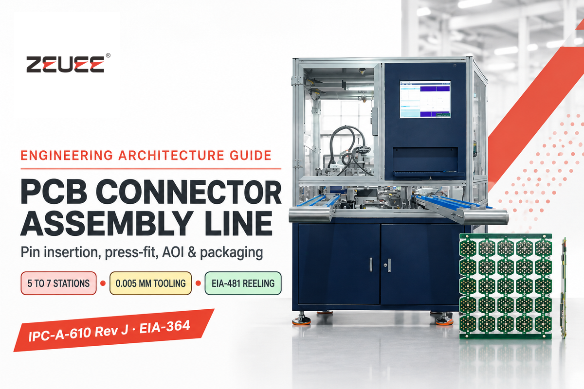
A PCB connector assembly line uses 5 to 7 synchronized stations to insert pins to 0.005 mm accuracy and to seal finished headers at high speed. Modular lines coordinate contact feeding, carrier cutoff, retention staking, optical inspection, Hi-Pot testing, and EIA-481 reel taping.
Many engineers mistakenly identify board-level PCB assembly automation lines with upstream connector automation lines. Although both lines serve the electronics manufacturing (supply chain), they solve different engineering issues. Component automation lines build uniform headers and sockets that survive downstream reflow and press-fit assembly without warped housings or weak joints.
A considerable rise in investment in board-level connector lines is being witnessed in industrial and automotive plants. According to Bishop & Associates market reporting, global connector sales grew 14.7% in 2025, adding over USD 12.7 billion in market expansion across Asia. Meanwhile, Future Market Insights PCB connector analysis forecasts dedicated board-level connector revenue climbing from USD 13.8 billion in 2025 to USD 19.7 billion by 2035 at a 3.6% CAGR. This guide breaks down polymer selection, press-fit mechanics, transfer topologies, IPC-A-610 Rev J and EIA-364 gates, OEE sizing math, and FAT readiness.
By Cherry · Updated November 2026
Quick Engineering Summary: Component Lines vs. Board PCBA
- Board lines populate bare printed circuit boards, and component lines stitch stamped terminals in molded housings, and pack EIA-481 reels.
- Glass-filled PBT polyester deflects at 182 to 204°C and fails IR reflow, whereas glass-filled LCP and PPS endure 260°C for 10 seconds.
- Between pin insertion and electrical Hi-Pot, inline AOI isolates bent pins. Bad units consume test cycle time.
- For module cavity tooling and pricing machines, see our turnkey PCB connector assembly line solution.
How Does an Automated PCB Connector Assembly Line Differ from Board-Level PCBA?
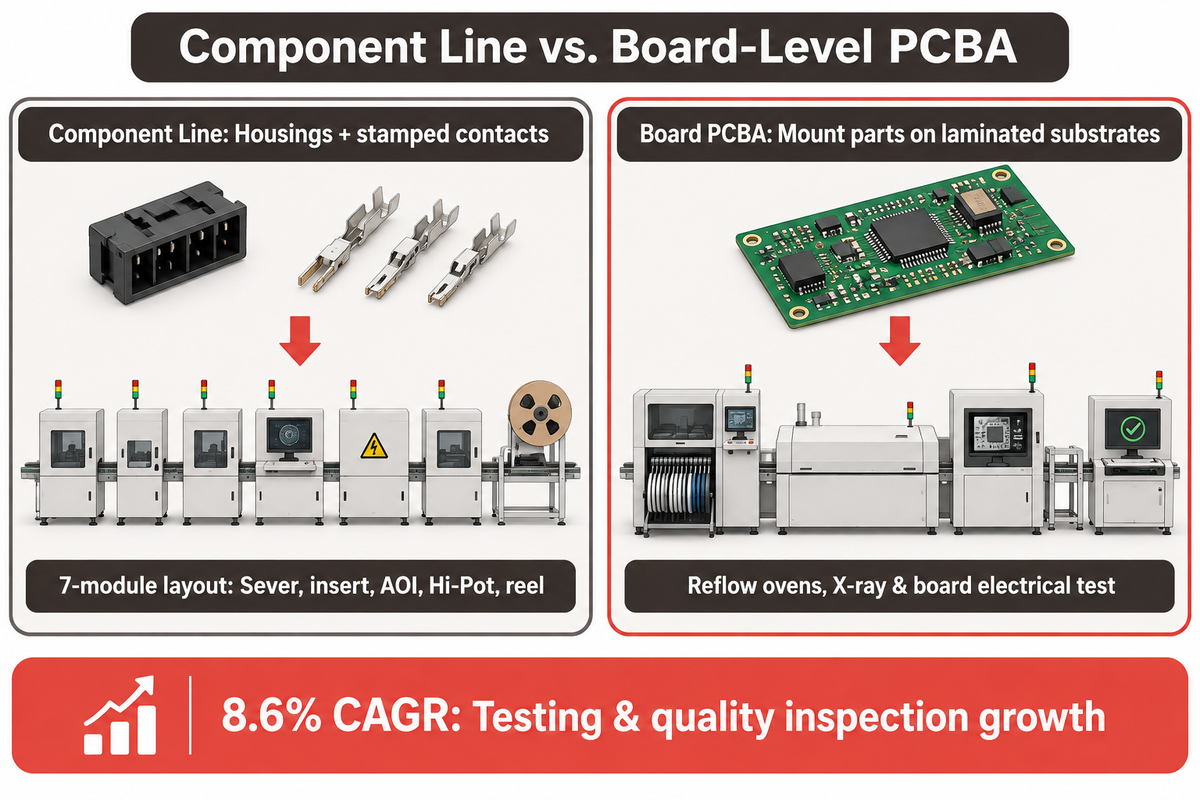
An automated PCB connector assembly line manufactures discrete interconnect components from stamped terminals and molded housings, whereas board-level PCB assembly mounts finished electronics onto laminated circuit substrates. The assembly plant then transfers finished boards through automated reflow soldering ovens and inline X-ray inspection stations for electrical test.
Misleading online tutorials integrate Printed Circuit Board Assembly (PCBA) with component automation and pcb design processes. Our analyses of leading online tutorials (PCBWay and Jaycon Systems) showed pcb design, bill of materials (BOM) kitting, and pcb assembly services processes. None explain how component factories stamp phosphor bronze contact strips, drive pins into narrow cavities, or check axial retention before shipping finished reels to an SMT line.
A connector line begins after injection molding and stamping presses complete raw parts. Raw materials include plastic housings, metal shields, and retention clips. In the upstream assembly process, automated modules sever pins from brass carriers and drive contacts into housings. Downstream stations check coplanarity via AOI and dielectric, and fit vacuum caps prior to reel packaging for finished board.
As ZEUEE’s 7-module production line layout shows, inspection bridges operate inline between mechanical and electrical steps rather than at batch shipping. Market spending reflects this shift toward inline verification. According to Fortune Business Insights assembly automation research, global assembly automation demand reached USD 35.63 billion in 2025, grew to USD 38.01 billion in 2026, and is projected to hit USD 66.91 billion by 2034 at a 7.3% CAGR. Asia-Pacific held 50.09% share in 2025, while testing and quality inspection leads growth at 8.6% CAGR ahead of vision systems at 8.1%.
Which PCB Connector Architectures and Materials Dictate Line Modules?
The design and construction of assembly automation systems is largely determined by three factors: the deflection temperature of the resin used in housing, the pitch of the centerlines of the pins, and the thickness of the module wall. Builds span thru-hole pin headers, SMT and SMD headers, card-edge sockets, RF blocks, and dual in-line package (DIP) frames across 2.54 mm, 2.00 mm, and 1.27 mm pitches, leaving thin walls between cavities.
Decisions on downstream soldering routes are made prior to automation based on mechanical pin geometry and standoff design. The technology used by connectors for soldering is stiff square posts coupled with rigid solder-wicking standoffs to provide a through-hole component for wave soldering. SMT devices require close coplanarity across long gull-wing rows to achieve lead connectivity. Press-fit headers avoid soldering completely by using thick push shoulders paired with elastic barrel zones for high mechanical strength. Keep bottom side clearances as per reflow fixtures on circuit board assembly.
Why do LCP and PA9T connector housings handle automated pin insertion differently than PBT?
Glass-filled LCP and PA9T survive 235°C to 260°C lead-free reflow profiles without bowing, whereas standard glass-filled PBT softens and distorts above 204°C. Connector Supplier’s solder warpage research notes that lead-free ovens cycling from 235°C to 260°C widen thermal expansion mismatch between copper pins and molded plastics. High-temperature resins hold pin true position steady during SMT processing, keeping reliable electronic connections intact on complex assemblies.
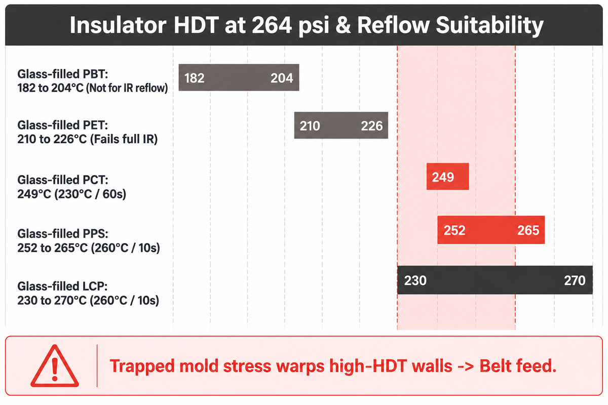
Thermal data in Samtec’s SMT plastics handbook sets clear resin boundaries at 264 psi load. Standard glass-filled PBT polyester carries a Heat Deflection Temperature (HDT) of 182 to 204°C and is graded not suitable for IR reflow. Likewise, glass-filled PET at 210 to 226°C fails full IR exposure. By contrast, glass-filled PCT reaches 249°C (230°C for 60 seconds), glass-filled PPS reaches 252 to 265°C (260°C for 10 seconds), and glass-filled LCP spans 230 to 270°C (260°C for 10 seconds).
Resin physics alters how feeders and insertion punches interact with housings on the factory floor. For example, LCP and PPS can be used to create thin-walled components that become very brittle from sharp edge impacts generated by vibratory bowls. Meanwhile, polyamide resins such as PA9T or PA66 absorb shop air humidity before assembly. With brittle or damp cavities, pressing pins dry can fracture wall dividers.
Though published HDT figures don’t always indicate permanent connector bow after soldering, Samtec indicates that higher HDT resins may warp more than lower HDT resins due to trapped molding stress and gate location. Asymmetric sections then relax and unevenly contract in the reflow oven. This risk is countered in automated connector lines by using gentle belt feeding, controlled cavity centering, and full-batch post-stitch tail planarity measurement.
| Connector Type & Architecture Tier | Typical Insulator Grade | HDT at 264 psi (°C) / Reflow Rating | Primary Molding & Feeding Constraint | Required Assembly Line Module |
|---|---|---|---|---|
| Type 1: Thru-Hole Wave Pin Header | Glass-Filled PBT Polyester | 182 to 204°C / Wave only (not IR reflow) | Flexible walls tolerate fast bowl rails | Vibratory bowl + rotary cam strip inserter |
| Type 2: SMT Gull-Wing Male Header | Glass-Filled LCP | 230 to 270°C / 260°C for 10 sec | Anisotropic bow from trapped mold stress | Vision belt feeder + 3D AOI coplanarity gauge |
| Type 3: High-Temp Right-Angle Header | PA9T High-Tg Polyamide | Lead-free reflow capable | Absorbs ambient moisture before pressing | Dry-air hopper + 90-deg rotary wipe former |
| Type 4: Micro-Pitch 1.27 mm Mezzanine | Glass-Filled LCP | 230 to 270°C / 260°C for 10 sec | Paper-thin cavity dividers crack on burr impact | 0.005 mm cutoff punch + optical pitch shuttle |
| Type 5: High-Power Board-to-Board Receptacle | Glass-Filled PPS | 252 to 265°C / 260°C for 10 sec | High rigidity increases clip snap brittleness | Coated linear rail + soft-grip tray loader |
| Type 6: Compliant Press-Fit Automotive ECU | PA9T or Glass-Filled PCT | 249°C (PCT) / Solderless press-fit | Total insertion force reaches 600 lbs / 60 pins | Closed-loop F(x) servo press + anvil support |
| Type 7: Card-Edge DIMM / PCIe Socket | Glass-Filled LCP or PCT | 230 to 270°C / 230 to 260°C rated | Long narrow slots twist without center clamping | Dual-datum pallet nest + multi-row servo stitch |
| Type 8: Shielded I/O Metallic Block | Glass-Filled PPS + Brass Shield | 252 to 265°C / 260°C for 10 sec | Axially offset retention latches hide half-seats | Shell forming + laser weld + multi-angle AOI |
| Type 9: Sealed High-Voltage EV Header | PA9T / PBT + Epoxy Seal | Wave or selective solder / potted | Insulation creepage requires bubble-free seal | Epoxy resin potting + correlated Hi-Pot probe |
| Type 10: High-Mix Prototype Header Batch | Mixed PCT / PA9T Rails | 230 to 260°C profile dependent | Short runs punish mechanical turret tooling swaps | Programmable X-Y SCARA / servo stitch cell |
Pin Insertion, Carrier Cutoff, and Compliant Press-Fit Mechanics
Brass or phosphor bronze terminals are retained in housings by a solder or press fit tail, in combination with a mating blade and a retention barb. A Custom manufacturing line takes a continuous, stamped band of contact and draws it through a cut-off die along with the housing.
Tight-pitch headers require closely tolerance machining. Dull punches leave small burrs on pin tips. If a burred pin enters a 1.27 mm cavity, it may shave housing walls. Debris then gets jammed under contacts, causes failures, and pins lose their true position.
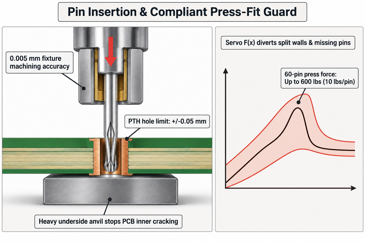
Tooling accuracy eliminates tip burrs and pitch cumulative error on long multi-pin headers. At ZEUEE’s Taihe manufacturing facility, core rod and contact pin fixtures are ground to 0.005 mm machining tolerances. Hardened guide bushings prevent thin pins from buckling during the insertion stroke. Optical or mechanical polarity checks also prevent incorrect contact elements from entering keyed housings.
Right-angle headers and sealed automotive modules add dedicated forming and joining steps on the production line. After straight axial pin insertion, a cam wipes the tail of the contact element to form a 90 degree bend. Sealed blocks may incorporate a weld tab to achieve a laser weld closure. For designs that use epoxy resin potting, potting stations complete the environmental seal.
When do high-density PCB connectors require compliant press-fit pins instead of soldered tails?
High-density boards require compliant press-fit pins when multi-layer automotive, high-frequency, or power backplanes can’t withstand wave-soldering heat shock or secondary reflow cycles. TE Connectivity’s press-fit connection architecture distinguishes rigid solid pins from elastic compliant pins such as ACTION PIN eye-of-the-needle terminals. Compliant beams, radially compressed against the drilled hole, form a gas-tight seal.
Forum consensus on Electronics StackExchange press-fit limits warns that hole accuracy near +/-0.05 mm and underside board support are mandatory. According to San Francisco Circuits strain guidelines, pressing a 60-pin connector reaches up to 600 lbs total force, or 10 lbs per pin. Without heavy underside support anvils directly beneath the connector footprint, multi-layer circuit boards flex and crack inner copper pads.
Closed-loop servo pressing guards against breakage of delicate plastics and damage to costly laminated boards in the course of performing assembly. Real time servo press force-displacement monitoring traces the force profile across every millimeter of the stroke. Hardened servo press rams drive mechanical insertion motion with repeatable stops and minimal tuning overhead. A missing assembly pin, split plastic wall, or a tight PTH barrel trips the force envelope. Should this happen, the system automatically diverts the defective assembly.
There are two primary latent press-fit defects attributable to workshop practices. Hourglass PTH plating inside thick PCBs shrinks elastic spring contact area and triggers intermittent opens under vibration. Worse still, if the workman isn’t vigilant, he might resort to solder to close the gap. Tin plunges into the split and destroys the elastic spring, leading to permanent brittleness. There are patents like automated terminal assembly CN121642705A that use a similar system to address mechanical issues and double-check to ensure hidden damage isn’t introduced.
| Tolerance Stack Item | Controlling Line Station | Physical Mechanism | Downstream Defect | Inline Guard / Gauge |
|---|---|---|---|---|
| Carrier Cutoff Tip Burr | Progressive strip die | Blade clearance controls burr edge | Shaved plastic slivers inside slot | Side 2D telecentric camera & die stroke counter |
| Barb Interference Fit | Mold core + servo ram | Oversize ribs split thin LCP | Cracked divider walls or pin push-out | Closed-loop F(x) insertion force envelope |
| Multi-Row Pitch Offset | X-Y servo stitching table | Encoder backlash drifts long spans | Tail misses EMS solder paste pad | Bottom laser true-position check |
| Compliant Zone Finish | Terminal plating & tooling | Cosmetic tinning ruins spring elastic recovery | Latent open circuit after thermal shock | Underside anvil support + pull-out audit |
| Secondary Latch Clip | Terminal locking station | Axial offset hides half-latched tabs | Contact backs out during plug mating | Multi-angle camera check (DE102024136228A1) |
Rotary Cam-Indexing vs Servo Stitching vs Linear Pallet Transfer Topologies
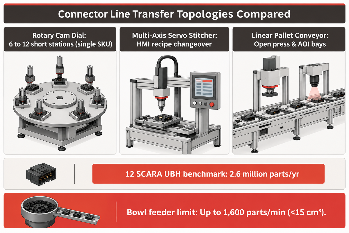
Transfer topology influences machine throughput, floor footprint, changeover time, and inspectability across your plant. Connector assembly line configurations include rotary cam-indexing dials, programmable servo stitchers, and linear pallet conveyors. The topology that best matches your SKU mix minimizes mechanical bottlenecks and changeover times.
Rotary cam-indexing dials deliver maximum raw output on stable single-family connectors needing 6 to 12 short stations. The indexing motion is driven by cams that have minimal wear and provide repeatable stops. Simple 2-pin to 10-pin straight headers fit rotary dials easily. However, dial circumference limits total fixture stations, and high-tonnage 600 lb pressing torques main center bearings.
Conveyor transfers decouple module count and turret size, making them ideal for configurations with large and heavy press-fit blocks and shielded sockets. As the press integration guides in Assembly Magazine detail, conveyors can easily be integrated to shuttle C frames under presses to eliminate upstream vibration. Open conveyor bays can also easily accommodate dedicated laser weld modules, 3D inspection bridges, and locked scrap diverters.
Multi-axis robotic and servo stitchers dominate high-mix, low-volume runs where rapid recipe switching matters most. A documented automotive benchmark in Assembly Magazine’s UBH connector case study uses 12 SCARA robots across modular stations to produce 2.6 million electrical connectors annually. In connector assembly, seven SCARAs take metal contacts from feed tracks, while five SCARAs assemble housing carriers. Software indexing is more flexible than hard cam tooling to account for cavity maps. Users planning specialized layouts can compare architectures in our custom connector assembly machine guide and our automotive connector assembly machine guide.
The speed of part feeding often limits the line, regardless of which transfer bed is carrying the part. According to IQS Directory’s vibratory bowl feeders guide, bowls can handle clean small parts (less than 15 cm³) at a rate up to 1,600 per minute, although bowl feeders are not suitable for every scenario. Bowl feeders aren’t always the best solution, as bowls can still tangle terminal strips. For stitchers, bandolier strip stitching eliminates terminal strips from tangling. For fragile LCP parts, a vision-guided system can be used to feed parts, to prevent damage, like tearing or abrasing, from belt contact.
| Line Attribute | Rotary Cam-Indexing Dial | Multi-Axis Servo Stitcher | Linear Pallet Conveyor Line |
|---|---|---|---|
| Best Production Fit | High-volume single SKU family | High-mix multi-row & variable pitch | Complex turnkey multi-module builds |
| Insertion Drive | Mechanical cam punch & slide | Programmable X-Y servo stitching head | Bandolier strip stitch + servo presses |
| Changeover Speed | Mechanical tooling nest swap needed | HMI software pitch recipe in minutes | Quick-lock carrier pallets + modular stations |
| High-Force Capacity | Low-to-medium dial bearing limits | Moderate pin insertion loads | Full C-frame anvil & press-fit loads |
| Test & Vision Space | Tight angular station slots | Compact post-stitch vision head | Unlimited AOI, Hi-Pot, and taping bays |
How Should Engineers Specify Inline AOI, Coplanarity, Pin Retention, and Hi-Pot Gates Under IPC-A-610 and EIA-364?
Strict inline measurement enforces current IPC active revisions: IPC-A-610 Rev J (March 2024), J-STD-001 Rev J (April 2024), J-STD-002 Rev E (November 2017), and IPC-7530 Rev B (January 2025). Once a team selects a rotary, servo, or conveyor topology, inline metrology supports inspection across production carriers. Citing the latest document versions avoids out-of-date audit criteria at automated inspection gates.
Scope precision prevents costly incoming quality disputes with contract electronics plants. Agility Tech’s IPC class comparison clarifies that IPC-A-610 covers Classes 1, 2, and 3 acceptability of printed board assemblies, while IPC/WHMA-A-620 applies strictly to wire harnesses. Calling out generic IPC compliance on a machine RFQ without specifying workmanship class and print tolerances invites rejection conflicts.
Electrical verification is based on established procedures within the EIA-364 connector test suite. Product blueprints such as TE Connectivity EP-II connector specs and Molex specification PS-47346-001-001 invoke the two core dielectric benchmarks. They require EIA-364-20 Dielectric Withstanding Voltage (1-minute hold) and EIA-364-21 Insulation Resistance (500 V DC for 2 minutes). These blueprints also call out testing for EIA-364-23 (low level contact resistance) and EIA-364-37 (contact force).
Inline production lines face a clear dwell-time boundary on electrical stations. However, pausing high-speed rotary or pallet lines for 60 seconds or 2 minutes per connector would reduce throughput. Automation engineers accelerate inline dielectric checks using higher screening voltage only after running correlation curves against full 60-second EIA-364-20 qualification tests. Verify your station inspection coverage by following the steps in our IPC and EIA compliance checklist tool.
Why should equipment specs anchor rejection thresholds to connector drawings rather than generic IPC-A-610 rules?
Equipment rejection thresholds must be derived from the approved connector print as IPC-A-610 evaluates mounted board solder joints, not bare component geometry, retention force, or coplanarity datums. Vague board workmanship books omit key features such as true position, housing warp, and barb seat depth. Drawing-anchored vision tolerances enable defect capture at the source rather than after reflow.
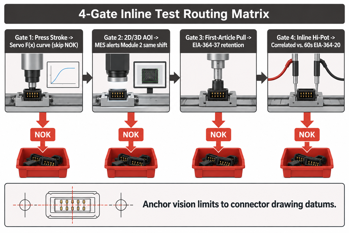
ZuchTech’s PCB header coplanarity analysis demonstrates that the planarity of tails is limited by the pitch of contacts, the length of leads, and the thickness of EMS solder paste. Fine-pitch gull-wing pins mounted over thin paste deposits allow much tighter elevation variance than coarse 2.54 mm board headers. Every visual inspection and AOI alarm limit on the assembly line must be anchored to the approved customer drawing datum.
The following structured 4-Gate Inline Test Routing Matrix is implemented by the top factories to avoid missed defects and false rejects.
| Gate Sequence | Sensing Technology | Target Measurement | Governing Standard | Routing & Traceability Rule |
|---|---|---|---|---|
| Gate 1: Press Stroke | Servo F(x) load curve | Peak seating force & travel stop | Connector drawing force envelope | Flag NOK pallet; skip electrical probe |
| Gate 2: 2D/3D AOI | Multi-angle CCD + laser height | Coplanarity, true position, latch lock | Part datum & multi-angle optics | Divert scrap; MES alerts Module 2 same shift |
| Gate 3: First-Article Pull | Benchtop digital force gauge | Axial pin retention & mating force | EIA-364-37 / first article log | Quarantine batch lot if retention drops |
| Gate 4: Inline Hi-Pot | Correlated Hi-Pot & continuity | Short circuit, open pin, breakdown | EIA-364-20 / EIA-364-21 / EIA-364-23 | Lock NOK bin upstream of taping reel |
How Do Factories Size Semi-Automatic Cells vs Turnkey Multi-Module Lines Using OEE and FPY?
Properly sizing lines determines availability and yield of a given quality level across the three tiers of automation: manual loading rigs, semi-automatic modular stitchers, and fully-automatic inline cells. Meeting production targets demands sizing shift capacity to account for station yield, including inline AOI and Hi-Pot pass rates. Compare labor shift payback to see if automated lines make economic sense inside our automated vs. manual sizing calculator and our tier line selector tool.
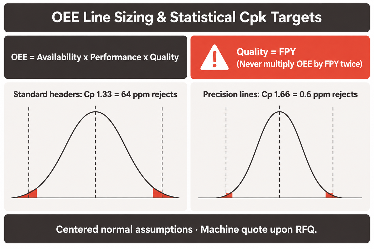
Purchasing teams must avoid a common calculation error when modeling Overall Equipment Effectiveness (OEE). The standard manufacturing equations set OEE equal to Availability times Performance times Quality. Engineering consensus on First Pass Yield (FPY) and OEE formulas reveals that Quality equals good parts over total parts when rework is excluded. Therefore, Quality equals FPY and shouldn’t be multiplied by FPY, because it would then be multiplied by FPY a second time. Doing so would double count defects and require a greater machine count.
There are multiple ways to derive the correlation between equipment defects and the capacities of a process, and both are related in numerous ways. Statistical process capability directly ties machine variation to customer defect rates. Defect rates are assigned an “acceptable” limit. The NIST Process Capability Handbook Section 6.1.6 defines bilateral capability as Cpk = minimum of (USL – mean)/3s or (mean – LSL)/3s. Across centered normal distributions, Cp 1.33 limits rejects to 64 parts per million (ppm), whereas Cp 1.66 drops bilateral defect risk to 0.6 ppm.
Use this Shift-Level Net Good Connector Sizing Ledger for estimating the size of semi-automatic cells versus fully-automated systems, prior to quotation:
| Sizing Formula Factor | Semi-Auto Stitch + Manual QC Cell | Turnkey 7-Module Inline Line | Engineering Governing Rule |
|---|---|---|---|
| Nominal Feed / Line Cycle | Constrained by manual housing load; bowls reach up to 1,600 parts/min only on simple parts | Continuous strip cutoff synchronized across 7 modules (0.5–5.08 mm pitch) | Model by bottlenecks, never bare feeder peak |
| Planned Shift Run Time | Net scheduled run minutes per shift | Net scheduled run minutes per shift | Exclude shift startup and break intervals |
| Availability Factor | Affected by tray refills and operator pacing | Affected by reel splices and bowl track jams | Ratio of actual run time to planned shift min |
| Performance Efficiency | Sensitive to operator placement rhythm | Stable mechanical or servo cam index rhythm | Ratio of ideal cycle time times count to run time |
| Quality Rate (Equals FPY) | Manual handling bends caught later in batch QC | Inline AOI & F(x) hold bad pins inside shift | Quality = FPY directly when rework is excluded |
| Net Effective OEE | Availability x Performance x Quality | Availability x Performance x Quality | Never multiply OEE by FPY a second time |
| FAT Capability Target | Lot sample pull audits per shift | Centered normal stability toward Cp 1.33 (64 ppm) or Cp 1.66 (0.6 ppm) | Pricing & net UPH remain project-quoted upon RFQ |
There are two strict engineering conditions regarding sizing outputs. Theoretical defect predictions such as 0.6 ppm at Cp 1.66 apply only to stable, centered normal distributions. Given the constraints, final machine pricing and lead times are project-quoted, upon RFQ.
End-of-Line Pick-and-Place Caps, EIA-481 Tape-and-Reel Packaging, and Defect Troubleshooting
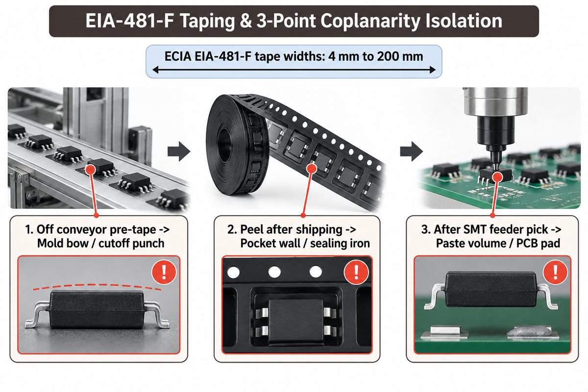
End-of-line packaging preserves header flatness for downstream SMT machines across ECIA EIA-481-F (2024 active standard) carrier widths from 4 mm to 200 mm. Protecting finished connectors during transit depends on accurate cap placement and clean tape sealing. Lines automatically seat Kapton vacuum pads or pick-and-place caps over mixed SMT components before heat-sealing pocket ends.
In ZEUEE’s 7-module architecture, inline AOI checks every header right after terminals are inserted and before electrical Hi-Pot probing. Defective parts are diverted immediately while MES diagnostics alert Module 2 technicians within the same shift, protecting downstream test probes and carrier reels from cumulative tooling drift.
How do feeder track jams and carrier cutoff burrs cause downstream tape-and-reel stoppage?
Feeder tracks tend to jam and cutoff burrs interrupt continuous tape and reel output by misfeeding housing ribs, shaving cavity plastic, and bending lead tails before headers enter carrier pockets. Tangled terminals lock in vibratory rails and indexing heads, thereby dropping line performance sharply. Burrs can also break heat-seal continuity.
When downstream EMS plants find open end-row solder joints after reflow, root-cause diagnostics should follow the three-point coplanarity check verified in ZuchTech’s reliability workflow:
- Check loose headers off the assembly conveyor before cap mounting or EIA-481 sealing to isolate injection mold bow, uneven cutoff punches, or stressed press nests.
- Peel connectors off sealed carrier reels after a shipping simulation to isolate tight pocket walls and overheated sealing irons.
- Inspect headers right after tape-feeder index and SMT nozzle pickup to help teams analyze stencil paste volumes and PCB layout pads instead of adjusting connector flatness.
Equipment Builders vs Component OEMs: RFQ Data Package and FAT Cpk Readiness
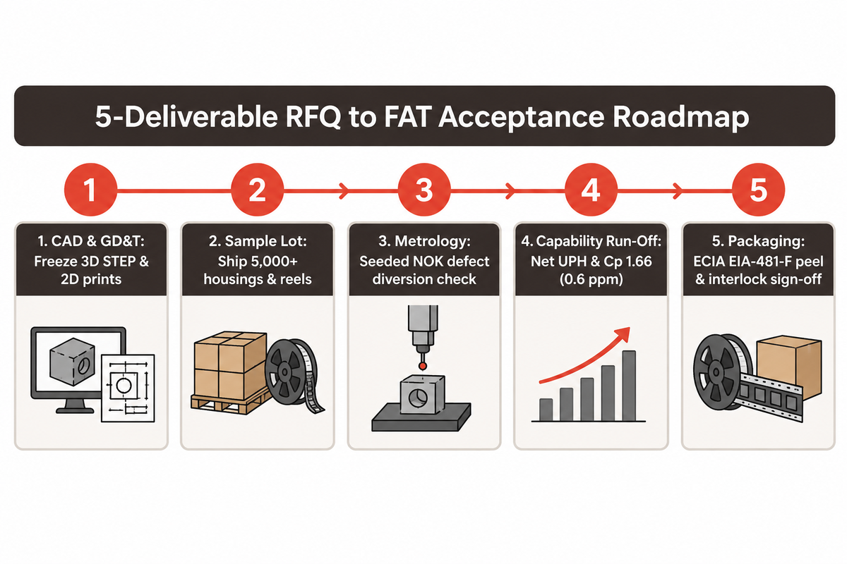
Reliable Factory Acceptance Tests (FAT) happen with complete drawings and sample exchanges between the component OEM and automation builder prior to steel machining. Preventing carrier burr and coplanarity faults starts with finalized drawings and agreed sample reels in the RFQ package. Delayed startups typically stem from mismatched CAD files, manual sample parts lacking production mold flash, or missing electrical test specs. Locking technical responsibilities at the RFQ ensures responsive delivery and first pass qualification.
Depth in manufacturing separates connector machine builders from integrators. Founded in 2005, ZEUEE (Shenzhen Zeyu Intelligent Industrial Science Technology Co., Ltd) operates a 20,000 m² plant in Taihe, Jiangxi with 120+ engineers and technicians. Backed by ISO 9001:2015 certification, CE compliance, 150+ patents (32 invention and 68 utility model patents), and installations in 30+ countries, our workshops machine critical core rods and fixtures to 0.005 mm accuracy.
Line up these five deliverables at the beginning of your project to speed up machine design review and FAT.
| Project Deliverable | Component OEM Input | Equipment Builder Scope | FAT Sign-Off Benchmark |
|---|---|---|---|
| CAD & Datum Drawings | Freeze 3D STEP models & 2D GD&T prints | Machine datum nests & pin guide bushings | Zero datum conflict between mold & fixture |
| Production Sample Lot | Ship 5,000+ molded housings & stamped reels | Tune vibratory bowls, tracks & cutoff dies | Zero feeder jams across sustained trial |
| Metrology & Test Spec | Specify IPC Class, retention & Hi-Pot dwell | Integrate AOI optics, servo F(x) & Hi-Pot | Golden seeded defect samples divert to NOK bin |
| Capability Run-Off | Approve sample plan and shift uptime rules | Run continuous shift test & export SPC logs | Hit quoted net UPH & Cp 1.66 (0.6 ppm) |
| Packaging & Safety | Confirm ECIA EIA-481-F tape & MES labels | Verify peel force & hardware interlocks | Signed FAT certificate releasing shipment |
Configure Your Automated PCB Connector Assembly Line with ZEUEE
Send your connector STEP drawings, terminal strip specs, and target shift output to ZEUEE’s engineering team. Our engineering team will provide station architecture, integrate AOI and Hi-Pot inspection, and provide a project-quoted FAT.
Request an Engineering Line Assessment Explore Turnkey Line Solutions
Frequently Asked Questions About PCB Connector Assembly Lines
What is the difference between a PCB connector assembly line and SMT PCBA?
A component line fabricates the connector itself, whereas SMT PCBA solders finished components onto bare circuit boards.
Component automation feeds stamped brass or phosphor bronze contacts, cuts carrier strips, inserts pins into molded housings, inspects tail coplanarity and electrical continuity, and seals headers into ECIA EIA-481-F reels. By contrast, an SMT board line prints solder paste through a stencil and mounts chips and finished connectors onto copper PCBs.
Which insulator polymer works best for 260°C reflow-soldered PCB connectors?
Glass-filled LCP (HDT 230 to 270°C), PPS (252 to 265°C), and PA9T survive 260°C lead-free reflow cleanly.
Per Samtec thermal handbooks at 264 psi load, glass-filled LCP (230 to 270°C) and PPS (252 to 265°C) hold pin geometry reliably across 10-second 260°C lead-free reflow peaks. Standard glass-filled PBT polyester deflects between 182 and 204°C and is graded unsuitable for IR reflow, restricting PBT mostly to wave-soldered through-hole board headers.
What Cpk target should factory acceptance tests meet on critical connector dimensions?
Automotive and fine-pitch lines specify Cp or Cpk >= 1.66 (0.6 ppm), while general headers accept 1.33 (64 ppm).
Under centered normal stability in the NIST Engineering Statistics Handbook Section 6.1.6, process capability Cp 1.33 corresponds to 64 theoretical rejects per million across bilateral tolerance windows. Tightening automated tooling precision to Cp 1.66 lowers defect exposure on critical pin pitch, seating height, and retention dimensions down to 0.6 ppm.
Why must inline AOI sit between pin insertion and electrical Hi-Pot testing?
Inspecting mechanically inserted headers immediately catches bent tails before bad connectors reach delicate Hi-Pot test probes.
Early AOI diverts splayed terminals and plastic shavings before electrical probing begins, protecting delicate Hi-Pot spring pins while alerting Module 2 technicians inside the same shift.
Why should factories avoid multiplying OEE by First Pass Yield when sizing lines?
The Quality factor inside standard OEE already captures First Pass Yield when offline manual rework is excluded.
OEE equals Availability times Performance times Quality. Without offline rework, Quality already equals FPY, so multiplying by FPY twice squares scrap losses and inflates machine budgets.
How do automated lines prevent compliant press-fit connector and PCB barrel damage?
Builders pair closed-loop servo presses with continuous force-displacement windows and rigid underside PCB anvil support.
Because seating a 60-pin compliant connector can require up to 600 lbs of force, servo press monitoring tracks insertion force across every millimeter of stroke. Any split housing rib, missing cavity pin, or undersized drilled hole trips the real-time F(x) envelope immediately. Custom milled underside support blocks eliminate PCB bending so buried inner copper layers never crack under press loads. Technicians also never apply cosmetic tinning or hand solder onto elastic compliant spring zones.
How should buyers prepare an RFQ data package for a turnkey connector assembly line?
Submit frozen 3D STEP models, 2D GD&T prints, EIA-364 test thresholds, EIA-481 tape specs, and production trial parts.
Clear technical boundaries prevent engineering delays before steel die blocks and nest fixtures get machined. Include frozen coplanarity datums, target hourly net output, required IPC workmanship class, and validated inline Hi-Pot correlation parameters against EIA-364-20 qualification rules. Shipping sufficient production-molded housings and stamped contact reels lets equipment builders test vibratory feeder clearance, progressive cutoff stability, and statistical Cpk capability runs on real factory materials before Factory Acceptance Test sign-off.
References & Sources
- Global Electronics Association (IPC), IPC Document Revision Table (IPC-A-610 Rev J, J-STD-001 Rev J, J-STD-002 Rev E, IPC-7530 Rev B).
- National Institute of Standards and Technology (NIST), Engineering Statistics Handbook Section 6.1.6: Process Capability (Cpk & PPM).
- Electronic Components Industry Association (ECIA), ECIA EIA-481-F (2024): 4 mm through 200 mm Surface Mount Embossed Carrier Taping.
- TE Connectivity, EP-II Connectors Product Specification (EIA-364-20 DWV & EIA-364-21 IR) and Press-Fit & Compliant Pin Technology.
- Molex, Product Specification PS-47346-001-001 (EIA-364 Electrical & Retention Grounding).
- Samtec Processing Engineering, SMT Handbook: Insulator Plastics Thermal Deflection & Reflow Matrix.
- Agility Tech, Evaluating Class 1, 2, and 3 Under IPC-A-610, IPC/WHMA-A-620, and J-STD-001.
- San Francisco Circuits, Press-Fit Connector Reliability & PCB Strain Thresholds.
- ZuchTech Engineering, PCB Header Coplanarity & Solder Joint Reliability Preservation Trials.
- Connector Supplier / Bishop & Associates, Global Connector Market Posts 14.7% Growth in 2025 and The Trouble With Solder Warpage.
- Assembly Magazine, Robots Automate Assembly of Automotive Connectors and Integrating Presses Into Assembly Systems.
- Fortune Business Insights & Future Market Insights, Assembly Automation Market Forecast (2025-2034) and PCB Connector Market Outlook (2025-2035).
- Kistler & IQS Directory, Compact Servo Press Force-Displacement Monitoring and Vibratory Bowl Feeder Throughput Guidelines.
- Patent & Practitioner Sources, DE102024136228A1, CN121642705A, Electronics StackExchange Press-Fit Consensus, and r/LeanManufacturing OEE & FPY Consensus.
WHY WE WRITE THIS
About ZEUEE Engineering Insights
ZEUEE shares technical guides based on real automation project experience. Since 2005, we have designed and manufactured non-standard automation equipment for connector assembly, wire harness production, robotic lines, vision inspection, and smart factory upgrades.
Founded in 2005
20,000 m² production base
120+ specialists
150+ R&D patents
ISO9001:2015 certified
Trending now