Get in touch with Zeyu lntelligent Industrial Company

Automated Assembly Line: Architecture, Capacity and Acceptance Guide

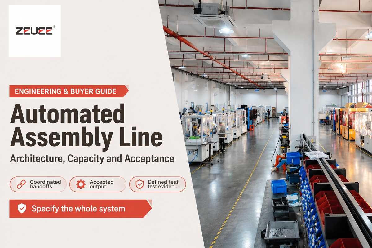
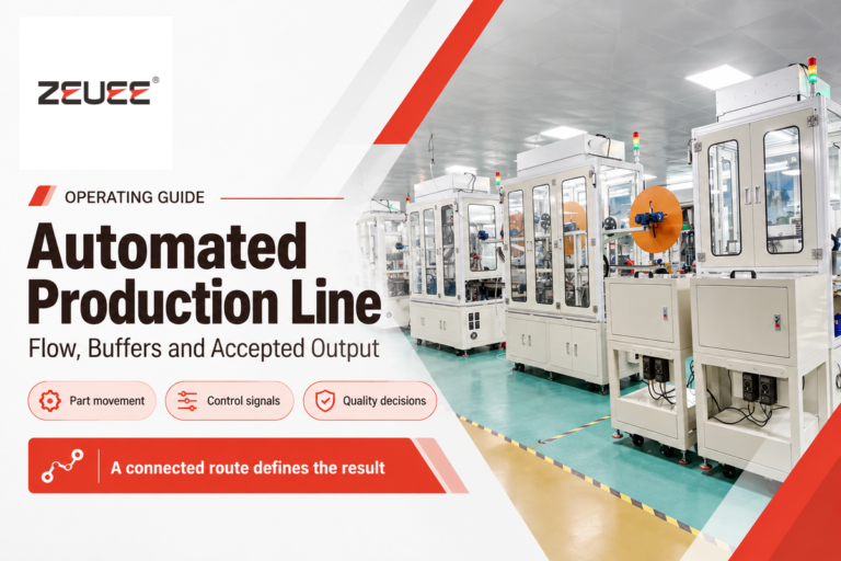
An automated assembly line connects machines that feed, position, join and inspect components to produce finished assemblies. Choose its transfer architecture around the slowest process, product variation and fault recovery. Then specify output as accepted parts per production period, so a fast demonstration cycle can’t hide deficits during a working shift.
Updated October 2026
Quick Specs: define the line before comparing machines
- Capacity basis: accepted assemblies per stated production period.
- Cycle basis: loading, processing, inspection and transfer included.
- Product envelope: component and fixture dimensions, weight and variants.
- Acceptance basis: agreed parts, operating conditions and recorded results.
An automated assembly line coordinates part feeding, workholding, assembly, inspection and controls. Its useful capacity is the number of accepted assemblies delivered, including the effects of stops, changeovers and rejects.
Key takeaways
- Keeping a difficult loading task manual can make an automated process more economical.
- A buffer absorbs short interruptions; recovery capacity matters afterward.
- Takt time follows demand; equipment cycle time must leave room for production losses.
- Acceptance should cover recovery, measurement and changeover as well as speed.
What Is an Automated Assembly Line and How Do Its Subsystems Work Together?
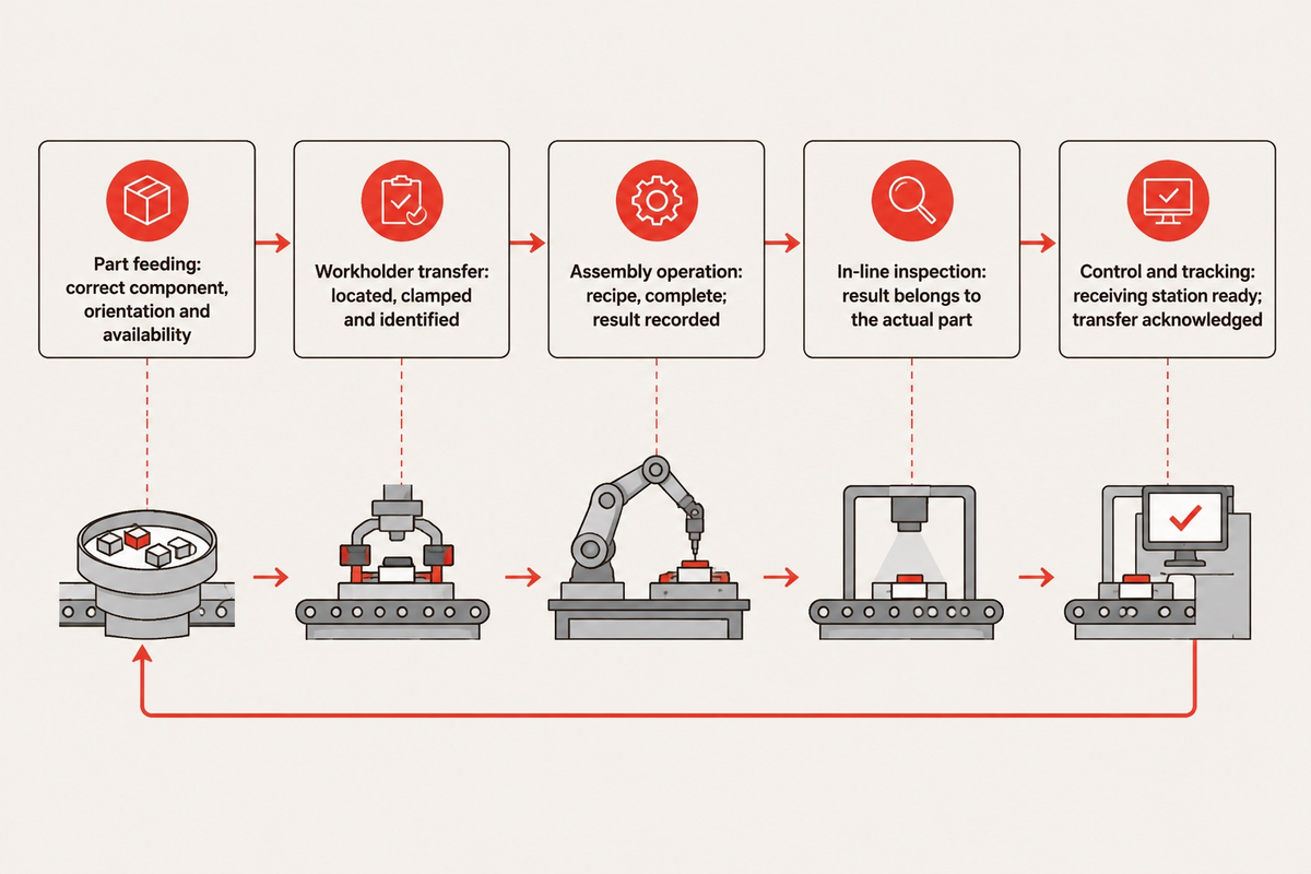
An automated assembly line moves a known part through controlled operations while preserving its identity and inspection status. It relies on coordination between operations to determine when a process is complete. A finished motion alone isn’t sufficient to indicate a process is complete; the next station needs a correctly located, eligible part.
An assembly line arranges tasks in a production sequence. Those tasks can be performed by people and/or machines. Automation adds control to the execution of the tasks and coordinated handoffs. The OPC Foundation’s machine-coordination interface illustrates why connected equipment needs explicit communication between upstream and downstream operations.
Consider a housing that receives an insert. A feeder presents the insert. A fixture locates the housing. A press performs the assembly. Inspection determines if it may continue. If the press reports completion before the result is assigned to that housing, downstream equipment may process the part based on an incorrect status. Therefore, both physical transfer and information ownership are required.
5-Layer Station Coupling Matrix
The 5-Layer Station Coupling Matrix maps each assembly function to its handoff condition and the consequence of losing that condition.
| Layer | Handoff condition | Failure if omitted | Responsible function |
|---|---|---|---|
| Part feeding | Correct component, orientation and availability | Empty pick or wrong component enters fixture | Process engineering |
| Workholder transfer | Part located, clamped and identified | Position error travels into joining | Mechanical engineering |
| Assembly operation | Recipe complete; process result recorded | Incomplete joint moves onward | Manufacturing engineering |
| In-line inspection | Result belongs to the actual part | Rejected assembly is released | Quality assurance |
| Control and tracking | Receiving station ready; transfer acknowledged | Duplicate movement or lost work-in-process record | Controls engineering |
What Is an Automated Assembly System Versus an Automated Production Line?
An automated assembly system joins previously made components. An automated production line system can integrate upstream manufacturing and downstream packaging. Assembly can take place in one cell or in several linked cells, which make up the production line. This distinction allows a manufacturer to determine if the equipment supplier owns component manufacture, assembly, testing or the entire production process.
For instance, a sheet metal bracket can be formed, and the component machined in a separate operation. Pressing the machined insert in the bracket creates an assembly. The automated production line guide covers the broader system boundary. Keeping that boundary explicit also prevents separate suppliers from assuming someone else will supply transfer tooling or reject handling.
How Do Rotary Indexing, Synchronous Linear, and Asynchronous Pallet Transfer Architectures Compare?
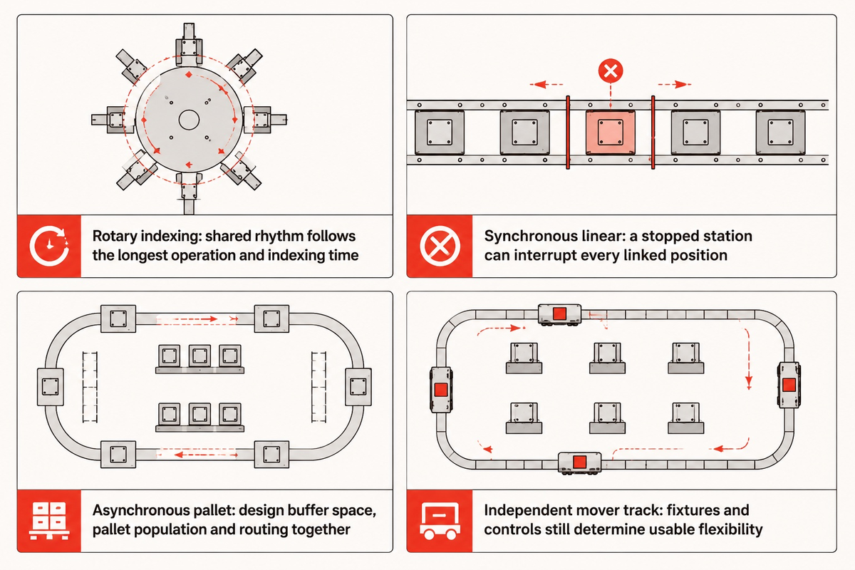
Choose rotary indexing for a compact sequence with compatible station times, synchronous linear transfer for operations that can advance together, and asynchronous pallets when stations need independent movement or waiting space.
| Architecture | Useful fit | Constraint to resolve |
|---|---|---|
| Rotary indexing | Compact, repeated assembly around a dial | Longest operation and indexing time govern the shared rhythm |
| Synchronous linear | Sequential operations with compatible dwell times | A stopped station can interrupt every linked position |
| Asynchronous pallet | Unequal process times, branch routes or independent stations | Buffer space, pallet population and routing require joint design |
| Independent mover track | Individually controlled travel and positioning | Process fixtures and control integration still determine usable flexibility |
In Bill Budde’s discussion of assembly throughput, too many pallets in a system can be just as detrimental to the flow of the system as a lack of pallets. A conveyor may need a model of the queue to justify the purchase, rather than simply a decision to buy more pallets.
For a concrete catalog example, Bosch Rexroth lists TS 1 workpiece pallet weight up to 3 kg and pallet sizes of 80 × 80 mm, 120 × 120 mm and 160 × 160 mm. Its stated positioning repeatability is ±0.015 mm. These are TS 1 parameters: pallet weight isn’t a promise of net component payload, and positioning repeatability isn’t finished-product accuracy.
Engineering note: Locate the product from the fixture datum used by the assembly process. Conveyor positioning, fixture variation and component variation contribute different errors; a catalog repeatability value should not be copied directly into a finished-assembly tolerance. ISO 10218-2:2025 addresses robot application safety, not a product’s dimensional acceptance tolerance.
Material handling outside the assembly system needs space too. AGVs delivering components require maneuvering and access for replenishment, without blocking maintenance doors. A modular conveyor can leave space for a future inspection branch. However, that expansion requires spare control capacity and a revision of the routing plan.
When Should You Choose Fixed Hard Automation vs. Flexible Robotic or Semi-Automated Assembly?
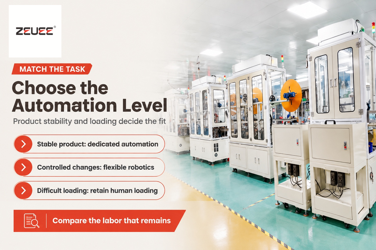
Choose dedicated automation for a stable product and repeatable operations, flexible robotic assembly for controlled changes in geometry or routing, and semi-automated equipment when human loading solves a difficult handling task economically. Consider the labor that will actually remain, changeover work and demand over the product life, before making the final choice.
Fixed automation can recover its extra fixed cost when automation savings per good part accumulate before the design changes. Compute crossover quantity by dividing the extra fixed cost by the savings per good part. Use the same scope of changeover, rejects, maintenance and labor for both alternatives. Dedicated mechanisms gain a cycle advantage when they perform compatible operations in parallel and the process dwell permits it. A cure, inspection, or loading bottleneck can remove that advantage, even if the mechanism itself is faster.
Dedicated automation advantages
Purpose-built tooling and coordinated parallel motions suit a stable, repeated assembly sequence.
Dedicated automation limitations
Geometry changes can require new tooling and engineering; the cost must be recovered within the remaining product life.
ASSEMBLY’s interviews with equipment integrators discuss a Genesis project in which large, irregular parts resisted conventional feeding and robotic bin picking exceeded the budget. Manual loading remained part of the solution. It’s an example of investment in automation following the process problem rather than assuming everything must be automatic.
Hypothetical selection example: A plant launches a thermoplastic housing in 3 variants, and the connector location is still changing during prototype builds. The production manager wants a test-and-insert machine, while the finance manager wants tooling that will last through the next revision. A semi-automated line can retain manual placement and automate the operations that determine quality and accuracy. Interchangeable nests then carry the variant-specific geometry. After the product design has stabilized, the team can evaluate a feeder upgrade against actual loading records. A dedicated feeding system from day 1 would tie more capital to an unsettled feature; keeping every operation manual would leave the precision task dependent on operator skill.
How Do Collaborative Robots and SCARA Arms Fit Into an Industrial Assembly Line?
SCARA arms suit repeated planar handling and insertion tasks, while collaborative robots can support applications designed for interaction with people. The actual reach, payload, tooling, motion and risk assessment need to be considered to determine if the robot is suited for the task at hand. Collaborative robot designation doesn’t guarantee the application is suitable for unguarded operation. The production rate of the application also needs to be assessed to confirm it meets the production goal.
Part of robotic production line integration is robotic automation. Feeding and inspection delays can dominate the cycle time even if the robot is moving quickly. For high-volume work, the relevant comparison is accepted assemblies per staffed shift including changeovers, rather than an isolated robot motion.
How Do Engineers Calculate Takt Time, Station Balancing, and Buffer Capacity?
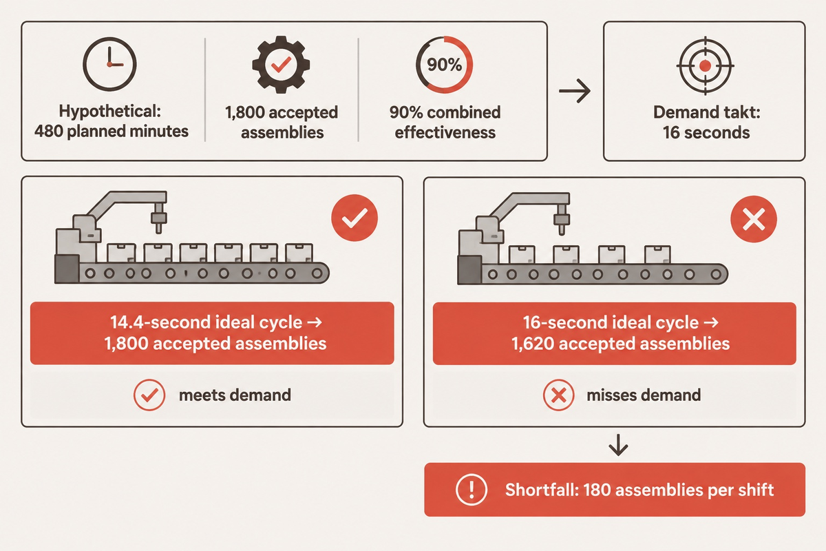
Find takt time by dividing the time available for production by customer demand. Next, pick an equipment cycle that can meet customer demand after considering availability, performance and quality losses. Balance station occupancy and size buffers by considering the effect of interruptions and the capacity to recover from the interruptions, rather than averaging speeds of equipment in the line.
“Takt time is a calculation of the available production time divided by customer demand.”
Hypothetical capacity example: A plant has 480 planned production minutes after breaks and needs 1,800 accepted assemblies. Takt is 480 × 60 ÷ 1,800 = 16 seconds per accepted assembly. Assume combined availability, performance and quality of 90%, with those losses not yet deducted from the 480 minutes. The corresponding ideal cycle ceiling is 16 × 0.90 = 14.4 seconds. At that ideal cycle, 28,800 ÷ 14.4 × 0.90 = 1,800 accepted assemblies. A supplier quoting a 16-second ideal cycle would instead deliver 1,620 accepted assemblies under the same assumptions. The shortfall is 180 assemblies per shift, even though the advertised cycle matches takt.
16 s
Demand takt
Demand takt
14.4 s
Ideal cycle ceiling
Ideal cycle ceiling
1,800
Accepted assemblies per shift
Accepted assemblies per shift
The University of Tennessee’s manufacturing extension guide defines availability, performance and quality factors. Deducting the same downtime or rejects twice would double count the loss. The Lean Enterprise Institute’s cycle-time definition also distinguishes the machine operation from effective cycle time including handling and allocated changeover.
For a simple buffer illustration, a downstream station consuming one part every 12 seconds needs 5 queued parts to ride through a 60-second upstream interruption. If upstream production stops for 1 minute, 5 parts would need to be queued up to ensure that production downstream of the 1 minute interruption would be uninterrupted. The queue must be present at the start of the interruption. In this case, buffer refills during upstream production wouldn’t be possible if upstream production resumes at exactly the downstream rate.
Massachusetts Institute of Technology’s buffer study demonstrates why equal average machine efficiency can still produce different buffer requirements when failure and repair patterns differ.
How Do Part Feeding, Precision Joining, and In-Line Vision Inspection Prevent Defects?
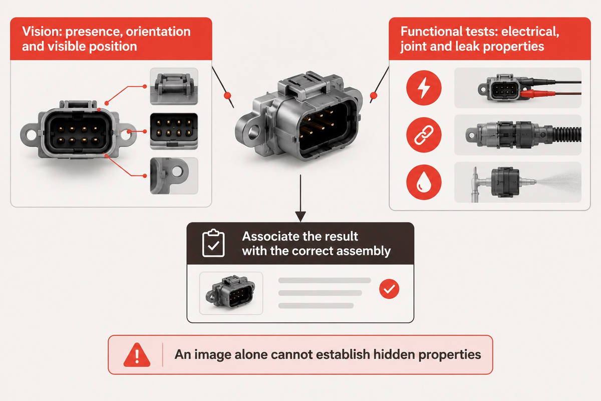
Assembly defects can be prevented by controlling component presentation and locating parts against defined datums. Measure the characteristic that determines joint quality. If the assembly defect is detectable at an inspection point, measure or verify before an irreversible operation. Each failure mode should be matched with the correct inspection to verify function.
For an adhesive joint or laser welding operation, process monitoring and final functional checks answer different questions.
The National Institute of Standards and Technology’s measurement guidance separates repeatability, bias and other error sources. Those distinctions should be made at an inspection station where the pass/fail result determines product release.
How Does In-Line Machine Vision Inspection Catch Assembly Defects Before End-of-Line Testing?
Inline machine vision inspection finds defects by checking visible features while they remain accessible and associating the result with the correct assembly. Typical tasks include presence checks, orientation checks and visible position checks. Hidden electric faults, condition of internal joints and leak performance require other types of tests. An image alone can’t establish these properties.
A feeder can present a damaged component perfectly. Likewise, a precise weld motion can join incorrectly located parts. Product quality therefore needs connected checks across assembly processes. Vision systems inspect visible features, while functional tests assess the final product. The following map helps process, quality and maintenance teams locate the loss before faster equipment is purchased.
| Loss category | Observed symptom | Evidence to inspect | Response |
|---|---|---|---|
| Feeding | Repeated empty picks | Presentation and replenishment records | Correct singulation before increasing pick speed |
| Part variation | Jams follow a component lot | Dimensions by lot or mold cavity | Align incoming tolerances and tooling |
| Location | Joining force drifts | Datum wear and seating checks | Restore the locating condition |
| Joining | Motion completes but joint fails | Process curve and product test | Correct the process window |
| Vision | False rejects vary by lighting | Images of known conforming and defective parts | Stabilize illumination and inspection criteria |
| Buffering | Downstream starvation after stops | Queue depth and repair duration | Provide recovery capacity and suitable storage |
| Traceability | Results appear on the wrong serial number | Part identity through every transfer | Repair result-to-part association |
| Changeover | First-off rejects after a variant change | Recipe, nest and component match | Verify the complete changeover state |
| Maintenance access | A short fault creates a long stoppage | Safe access, diagnosis and spare availability | Improve recovery without bypassing protection |
A hinge assembly machine presents different joining and gauging tasks from a connector line. The map is still useful because it separates the observed loss from the equipment label.
How Do PLC Controls, Station Handoff Logic, and MES Traceability Coordinate the Line?
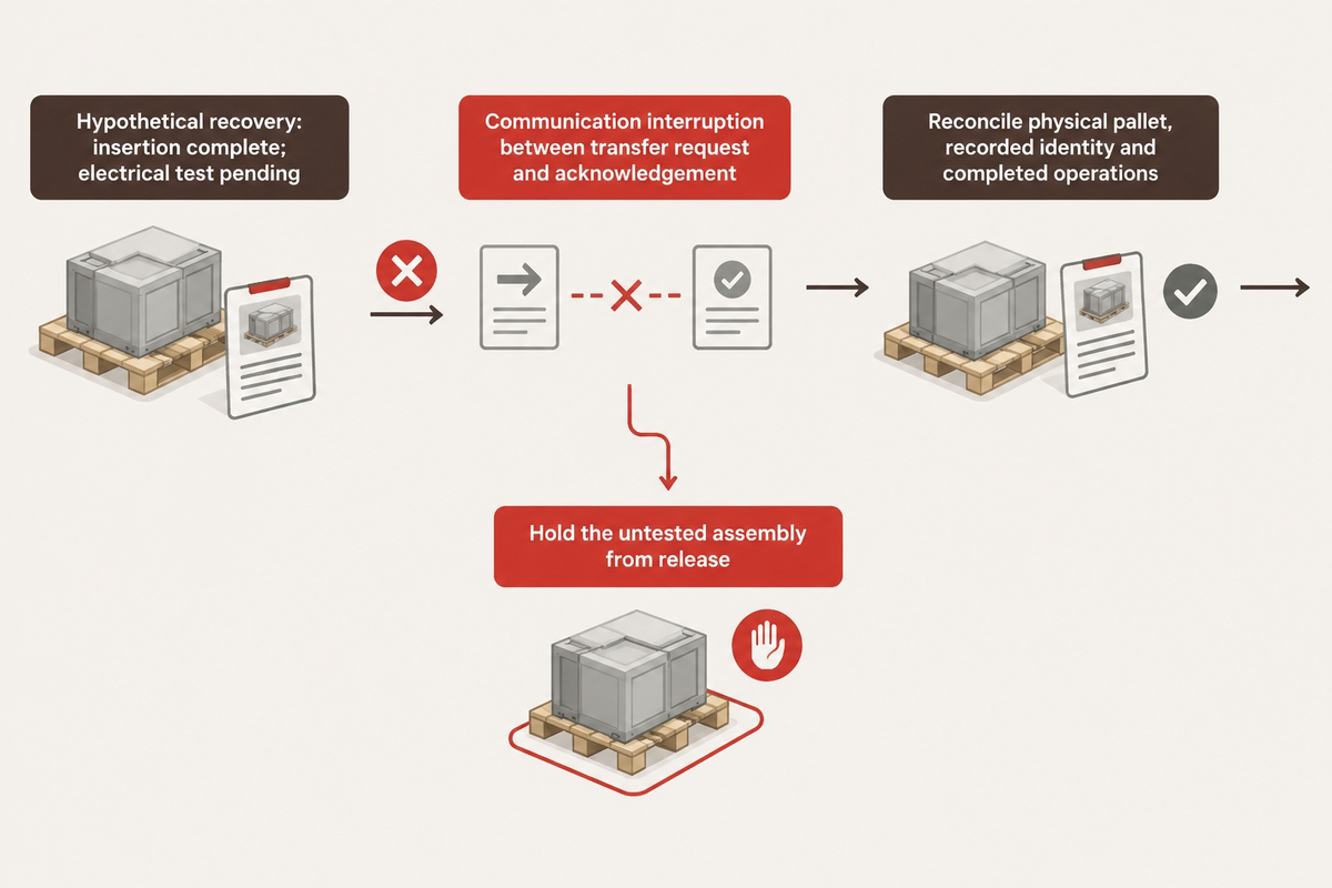
Programmable Logic Controllers support station readiness, transfer authorization, operation completion, and fault recovery. A Manufacturing Execution System (MES) can link production orders and traceability records; however, the local control sequence has to retain part identity during communication lapses. Describe who owns each transition, how it’s acknowledged, and what happens following an interruption.
The OPC Foundation’s PackML remote-interface description covers coordination between machines. Its material-interlock description leaves relevant semantics to suppliers. A shared interface therefore needs an agreed meaning for signals, not just a successful network connection.
Hypothetical recovery example: A pallet carries a housing that has completed the insertion operation, but the electrical test is pending. A communication interruption happens between the transfer request and its acknowledgement. On restart, blindly repeating the request could result in the housing being moved a second time, and clearing the records would result in loss of process history. The controls engineer needs a recovery state that reconciles the physical pallet, recorded identity and completed operations before movement resumes. Quality staff need the untested assembly held from release. Production needs a clear operator instruction for resuming work. Testing this boundary with production-intent components reveals more about usable integration than watching uninterrupted automatic cycles during a demonstration.
Real-time dashboards enable diagnosis when downtime categories reflect the actual manufacturing process. Recording every stop as “robot fault” hides whether the cause was a missing component, blocked receiver or inspection delay. Those differences determine whether to invest in factory automation hardware, component quality or controls.
What Drives Automated Assembly Line Cost, Lead Time, and Payback Period?
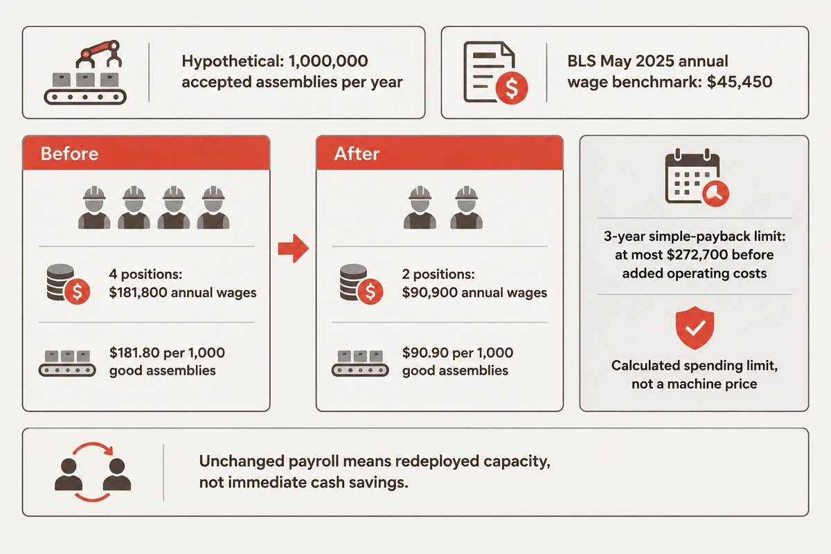
Custom tooling, process development and integration are key factors driving cost and schedule for assembly projects. Costs associated with commissioning and inspection also impact capital cost. Calculate payback from recoverable annual cash savings after added operating costs, using an installed project quote. Labor costs fall only when staffing changes. Released operator time is a valuable resource, but it’s only payroll savings when staffing, overtime or hiring changes.
The U.S. Bureau of Labor Statistics reports a May 2025 median annual wage of $45,450 for assemblers and fabricators. Using that wage-only benchmark, a hypothetical reduction from 4 to 2 full-year positions releases $90,900 annually. At an assumed 1,000,000 accepted assemblies per year, direct wages fall from $181.80 to $90.90 per 1,000 good assemblies. Other costs, such as benefits, overtime, supervision and local wage differences are excluded.
| Measure | Before | After |
|---|---|---|
| Full-year positions | 4 | 2 |
| Annual wage benchmark per position | $45,450 | $45,450 |
| Total direct wages | $181,800 | $90,900 |
| Direct wages per 1,000 accepted assemblies | $181.80 | $90.90 |
For a hypothetical 3-year simple-payback target, that wage difference supports at most $272,700 of investment before additional annual operating costs. This is a calculated spending limit, not a machine price. Annual savings, less maintenance, energy, consumables and support, should be multiplied by 3 years. Keep taxes, financing and discounting in the full financial model.
If the 2 operators are reassigned and payroll remains unchanged, finance should record redeployed capacity rather than immediate cash cost savings. The plant manager may still justify the investment through avoided overtime or added saleable production. That justification is why return on investment needs an agreed labor and demand scenario rather than a productivity percentage.
Design approval, ordering of long-lead components, integration and production-part trials should be in a supplier’s schedule. Turnkey automation systems and other turnkey solutions can consolidate responsibility, but the quotation still needs clear boundaries for utilities, installation and acceptance. A lower initial quote can become less cost-effective when these items are excluded.
How Do Factory Acceptance Testing (FAT), Site Acceptance (SAT), and Changeover Verification Work?
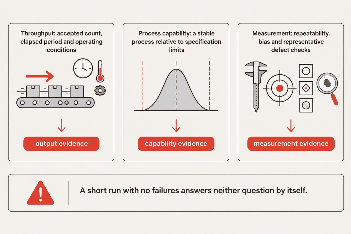
Factory acceptance testing (FAT) verifies function of a machine with respect to an agreement. It’s performed on a machine prior to shipment. Site acceptance testing (SAT) demonstrates the same with respect to performance after installation in the production environment. Use production-intent components and defined operating conditions for both tests. Test throughput, quality, recovery and changeover separately, because a successful speed run does not establish measurement accuracy or long-term process capability.
Eclipse Automation’s commissioning guidance focuses on representative parts, sustained running and readiness of site utilities and networks. The National Institute of Standards and Technology’s process-capability guidance addresses a stable process relative to specification limits. NIST’s measurement-process guidance looks into measurement error separately. A short run with no failures answers neither question by itself.
| Acceptance item | Recorded evidence | Decision owner |
|---|---|---|
| Good-part output | Accepted count, elapsed production period and operating conditions | Production |
| Station occupancy | Load, process, inspect and transfer timing | Process engineering |
| Component variation | Results across agreed lots, cavities and dimensional conditions | Quality assurance |
| Inspection validity | Measurement repeatability, bias and representative defect checks | Metrology |
| Reject containment | Failed parts identified and prevented from release | Quality assurance |
| Fault recovery | Controlled recovery with part state and identity retained | Controls and maintenance |
| Variant changeover | Last good part to verified first good part; tooling and recipe changes | Production |
| Site integration | Utilities, network connections and upstream/downstream handoffs | Facilities and integration |
| Handover package | Software backups, drawings, training and maintenance documents | Maintenance and procurement |
Safety review also needs a defined boundary. From a safety review’s perspective, for servicing covered by the U.S. 29 CFR 1910.147, control-circuit devices aren’t energy-isolating devices. Apply the regulation’s scope and exceptions to the actual task; an ordinary stop command shouldn’t be treated as an isolation procedure.
Prepare one quotation and acceptance package
- Provide drawings, representative components and the planned product family.
- State accepted output, production calendar, quality criteria and changeover pattern.
- Assign utilities, data interfaces, installation and acceptance responsibilities.
- Request itemized exclusions, milestone dates and the proposed test evidence.
Procurement can then compare automation solutions against the same scope. Manufacturing companies gain more from a comparable acceptance package than from a headline claim of “high-speed assembly.”
HAHN Automation Group has released a connector-assembly example on feeding and inspection, and Eclipse Automation has published guidance on assembly-line integration and commissioning. These can be beneficial in similar cases. ZEUEE’s assembly-line enquiry page, below, provides a means to discuss a custom project within the same scope and acceptance criteria.
Industry Outlook: Application-Specific Integration and the 2025 Robot Safety Update
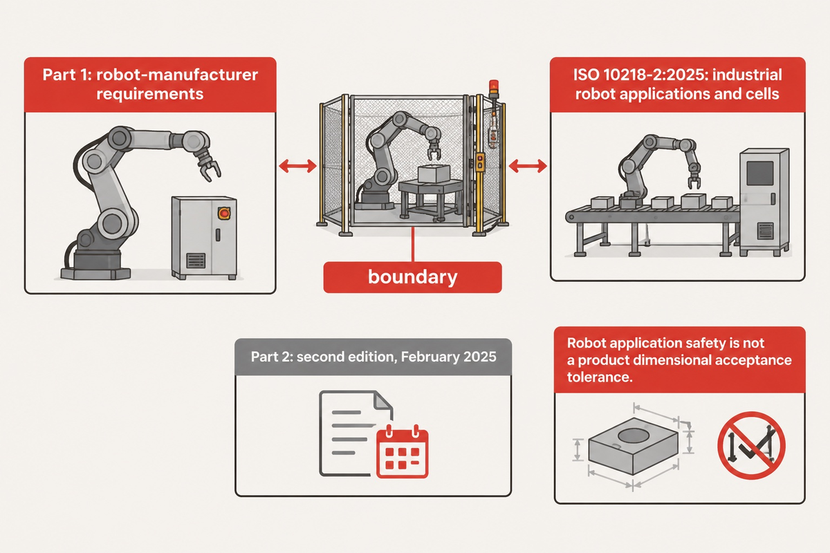
Application-specific integration will remain central as robot safety guidance continues to evolve. ISO 10218-2:2025 addresses industrial robot applications and cells, and project specifications should identify the applicable edition and responsibilities. Automotive, consumer electronics and connector assembly also require different types of evidence for the process, even if their automation systems use the same robot, conveyors and controls.
The International Organization for Standardization published the second edition in February 2025. The Association for Advancing Automation elaborates on robot-manufacturer requirements in Part 1 and application and cell integration in Part 2.
For automotive assemblies, joining records and component pedigrees may drive the specification. Consumer electronics can place more weight on small-part handling and cosmetic protection. Medical production requires its own product and process requirements, rather than inheriting an automotive acceptance plan. Manufacturing technology is valuable in addressing these requirements. An agile or scalable layout would still require validated changeover and inspection.
When product roadmaps support reserving expansion interfaces for an investment in automation technology, this gives the integrator a concrete future requirement and keeps the initial build focused. Competitiveness and profitability follow usable capacity and quality, not the quantity of automated production equipment installed.
Frequently Asked Questions
What does the term “automated assembly line” mean in modern manufacturing?
It means linked equipment assembles components with coordinated handling, processing, inspection and controls.
A standalone machine may automate one operation; a line also manages movement and work-in-process between operations. Its output should be defined as accepted assemblies over a stated production period. That definition includes the practical effects of stoppages, rejected parts and product changes, which a single machine’s demonstration cycle can leave out.
How do you know when a manual assembly process is ready to automate?
A process is ready when its product requirements, repeatable operations and production demand are sufficiently defined for equipment design.
Document current cycle times, recurring defects, component variation and operator tasks before choosing hardware. Stable precision operations may be ready even when feeding remains difficult. A prototype product with changing geometry may suit interchangeable fixtures and manual loading first, allowing later investment to follow actual production evidence rather than an assumed final design.
What is an example of an automated assembly system in industrial production?
A connector assembly system can load housings, insert contacts, check insertion and perform an electrical test.
The stations share the component’s identity so inspection results follow the correct connector. A rejected part needs a controlled route that prevents release as good product. The exact arrangement follows contact geometry, handling requirements and the specified tests; the same sequence can use dedicated mechanisms, robots or a combination with manual loading.
Can an automated assembly line handle multiple product variants on one system?
Yes. Compatible variants can share equipment through changeable nests, controlled recipes and suitable feeding. The specification must define which features change and how first-off quality is confirmed. A shared robot alone doesn’t make incompatible components or inspection methods interchangeable.
What causes unplanned downtime on an automated assembly line?
Part-feeding faults, component variation, tooling wear, inspection instability and control handoff errors can interrupt production. Separate the immediate alarm from the underlying cause: an empty robot pick may originate at the feeder, while a blocked conveyor may reflect a downstream inspection delay. Record fault duration, repair actions and queue conditions. That history helps maintenance prioritize recurring losses and helps engineering decide whether the next improvement needs different tooling, better parts or revised recovery logic. For example, repeated short feeder interruptions call for a different response from a rare but lengthy repair, even when the lost production time totals the same amount.
Which project milestones belong in an automated assembly line delivery schedule?
Include design approval, component procurement, mechanical build, controls integration, production-part trials, factory acceptance, shipment, installation and site acceptance. Assign customer inputs to the same schedule. Late drawings or trial components can delay validation even when the machine build itself is finished.
What should buyers prepare before requesting a quote from automated assembly line manufacturers?
Prepare component drawings, sample parts, accepted-output requirements, variant plans, inspection criteria and the available factory layout. Include the production calendar and the expected staffing arrangement so suppliers calculate the same capacity requirement. Identify interfaces to existing equipment and production records. A useful request also assigns installation, utilities and acceptance responsibilities, allowing procurement to compare the complete installed scope and discuss exclusions before selecting a manufacturer. Attach representative good and defective components where available, and identify any product revisions still under development so proposed tooling doesn’t assume a frozen geometry.
Discuss Your Assembly Line Requirements
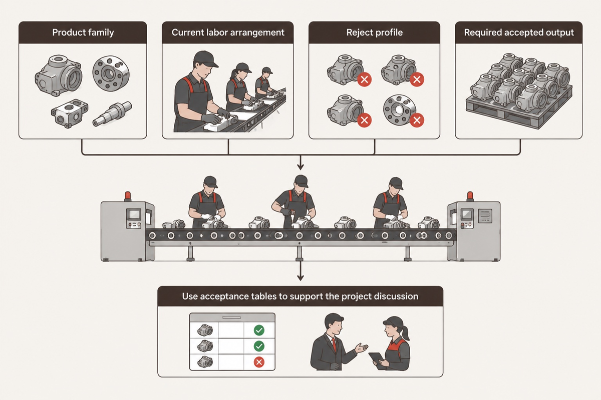
When the equipment discussion starts, bring your product family, current labor arrangement, reject profile and required accepted output. For project enquiries, the next step is the custom automated assembly line solutions page from ZEUEE. Use acceptance tables to support your case and review ZEUEE’s company information when creating your supplier shortlist.
Related Articles and Solutions
- Production line scope and planning
- Turnkey project responsibilities
- Robot-based production systems
- Hinge assembly equipment
References & Sources
- Lean Enterprise Institute: Takt Time and Cycle Time.
- University of Tennessee Center for Industrial Services: OEE Implementation Guide.
- Massachusetts Institute of Technology: Buffer Optimization.
- U.S. Bureau of Labor Statistics: Assemblers and Fabricators, May 2025 wages.
- National Institute of Standards and Technology: Process Capability and Measurement Process Characterization.
- OPC Foundation: PackML Remote Interface and Material Interlock.
- International Organization for Standardization: ISO 10218-2:2025; Association for Advancing Automation: Updated ISO 10218 FAQ.
- Electronic Code of Federal Regulations: 29 CFR 1910.147.
- ASSEMBLY: Defining Throughput in Automated Assembly Systems; Manual, Semiautomatic or Fully Automatic?
WHY WE WRITE THIS
About ZEUEE Engineering Insights
ZEUEE shares technical guides based on real automation project experience. Since 2005, we have designed and manufactured non-standard automation equipment for connector assembly, wire harness production, robotic lines, vision inspection, and smart factory upgrades.
Founded in 2005
20,000 m² production base
120+ specialists
150+ R&D patents
ISO9001:2015 certified