Get in touch with Zeyu lntelligent Industrial Company

Fiber Optics & Telecom Explained: From Glass to Connected Networks


Industry guide · Updated September 2026
Fiber Optics & Telecom is the connected value chain from optical fiber and cable through passive components, active equipment, deployment, testing, and service handoff. One cable datasheet alone cannot prove that a link or production package is ready: route, transceivers, connectors, test evidence, and change control must agree.
At a glance: Fiber selection is a reach, environment, and transceiver decision, not a “best fiber” contest. Credible handover packs combine visual cleanliness, loss, fault-location, and polarity evidence. Automation becomes useful after the product family, interfaces, inspection points, and acceptance records are stable.
- Use the layer map before debating a component list.
- Design a link budget from the actual route and margin, not nominal reach.
- Document who owns each test record and each change authorization decision.
- Review fiber-optics and telecom automation solutions only after a production package is defined for a commercial discussion.
Fiber is the medium; the project outcome depends on the evidence chain around it.
What Does Fiber Optics & Telecom Include?
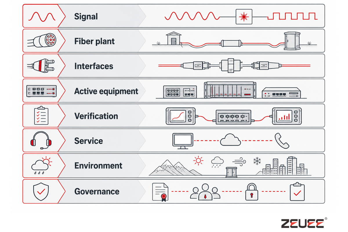
The phrase covers more than a strand of glass. The physical layer includes glass fiber, coating, cable construction, splice closures, patch panels, connectors, splitters, and enclosures. The active layer includes transceivers, optical line terminals, switches, routers, amplifiers, and monitoring equipment. Service operations connect those layers to access, transport, data-center, enterprise, and mobile-backhaul applications. That medium frames the layer map below; the FOA reference library provides the practical terminology behind these layers.
| Layer | Typical objects | Question | Evidence owner |
|---|---|---|---|
| Signal | Laser/LED source, wavelength, modulation | What optical budget and protocol leave the transmitter? | System architect |
| Fiber plant | Fiber, cable, splice, closure, duct | Can the route protect margin over its environment and life? | Plant designer |
| Interfaces | Connector, adapter, polarity, patching | Can technicians mate, inspect, label, and rework the interface? | Integration lead |
| Active equipment | Transceiver, OLT, switch, router | Do optics, firmware, power, thermal limits, and coding agree? | Network/IT owner |
| Verification | OLTS, OTDR, microscope, records | What independent test proves release? | Quality lead |
| Service | Monitoring, spares, change control, SLA | How will a fault be found and restored without guessing? | Operations owner |
| Environment | Route, temperature, bend exposure, enclosure | Which installed conditions can change the optical margin? | Site engineer |
| Governance | Revision, exception, approval, replacement | Who accepts a change and its retest requirement? | Project owner |
The optical map provides a guide and prevents common errors where a transmission plant defect is incorrectly attributed to the active equipment; after all, a switch cannot compensate for a contaminated connector, and a higher-count cable cannot compensate for an undocumented polarity change. Don’t begin an economic assessment before establishing informational scope and parameters.
Scope is where teams often hide the first failure. Cable-only briefs create mismatch between the route, optic, connector, test record, and owner because each group assumes a different boundary. Give a buyer or deployment team a 10 km route example, a production variant, an IEC 61300-3-35 connector-inspection reference, and a named evidence owner before a design review; the point is to expose gaps early, not to imply a universal configuration.
How Does Light Become Data, and Where Can Loss Enter?
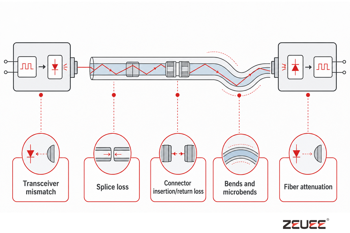
The transmitter converts electrical symbols into modulated light. The higher-index glass core and lower-index cladding confine that light before a receiver converts it back. Attenuation, dispersion, reflections, connector coupling, and splices explain why an installed route differs from a laboratory link. The link budget records whether enough optical margin remains; the FOA fiber-optics reference library covers the terminology behind those propagation concepts.
Start the link budget with the actual fiber family, operating wavelength, route length, splice count and method, connector pairs, planned repairs, bend-sensitive areas, and transmitter/receiver limits. Add engineering margin for aging, temperature, installation uncertainty, and future work. Nominal “10 km” or “40 km” optic labels are not field guarantees.
| Loss/risk | What changes | Record |
|---|---|---|
| Fiber attenuation | Available receiver power | Wavelength, fiber class, route, assumed dB/km |
| Splice loss | Margin and repair repeatability | Splice count, method, result, location |
| Connector insertion/return loss | Power and reflections | Connector type, reference method, inspection |
| Bends and microbends | Intermittent, wavelength-dependent loss | Bend requirement, routing photos, repair history |
| Transceiver mismatch | Link can fail despite good passive plant | Part number, coding, firmware, temperature/power |
A Two-Pass Review provides first the total expected budget, then a list of criteria that would challenge its accuracy, such as a high-loss OTDR event, an unexpected return-loss reading, an out-of-family optic, or a bend that is missing from the drawing. This approach supports a systematic response when an incident is reported as “no traffic is flowing.” When a failure persists, compare the result with the applicable ITU-T G.650.3 method because an apparently normal 10 km route can still contain a dirty interface or a bad reference. For a standards-based check, record the 1310 nm and 1550 nm results required by the acceptance plan, plus ambient temperature and the agreed dB limit.
Single-Mode vs Multimode Fiber: Which Fits the Link?
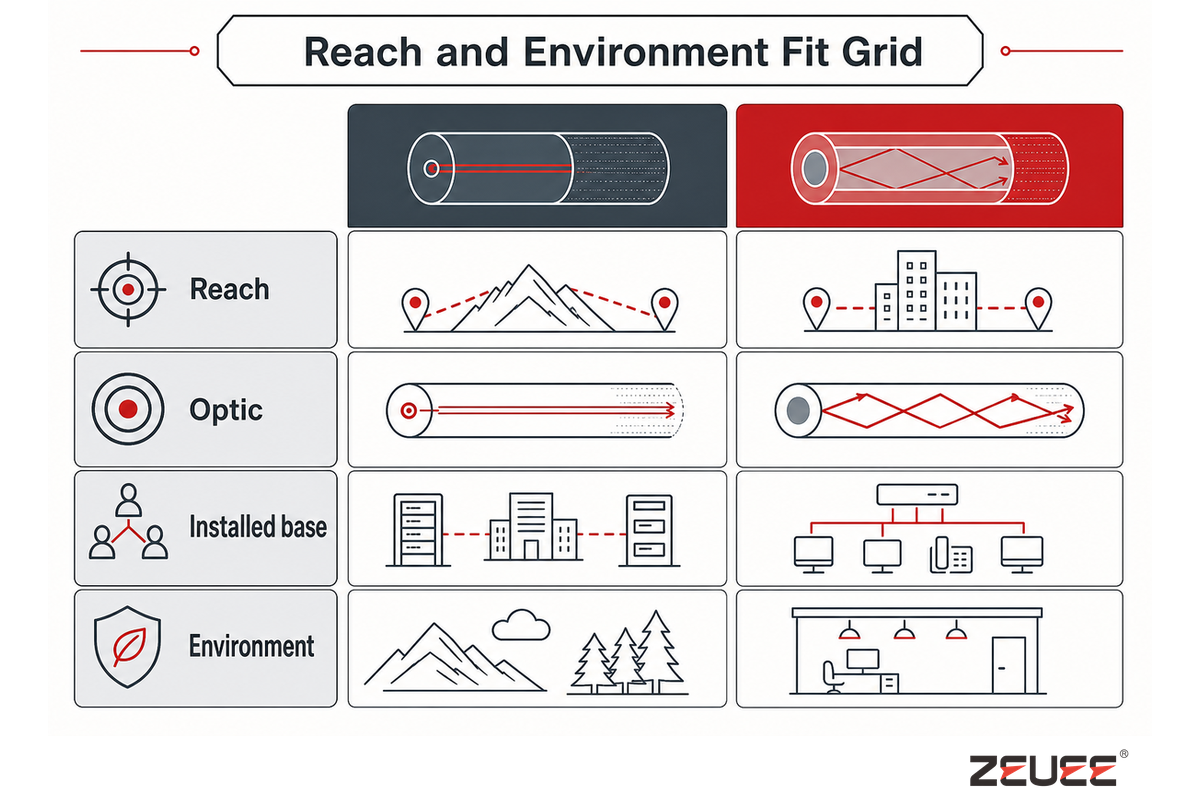
Single-mode and multimode fiber are not better or worse grades of technology. Multimode fiber suits optical networks inside buildings and data centers, where reach depends on the transceiver, wavelength, data rate, and cable grade. Single-mode (SM) fiber types such as G.652 or G.657 suit campus, metro, access, and wide-area links measured in kilometers, with practical reach set by optics, margin, dispersion, and the installed route. The G.652 recommendation is the standards signpost for single-mode terminology.
Instead of asking a vague question such as “is the cable good?”, ask, “Are the optic, fiber type, connector type, route, and future migration path appropriate for this project?” The adopted ITU-T G.652 or G.657 specification, its edition, and the project parameters must be stated and integrated into the contractual framework.
Reach and Environment Fit Grid
| Variable | Single-mode tendency | Multimode tendency | Evidence |
|---|---|---|---|
| Reach | Long campus, metro, access, interconnect | Shorter building or room links | Route length and loss budget |
| Optic | 1310/1550 nm families are common | Short-wavelength VCSEL ecosystems are common | Matched optic data sheet and coding |
| Installed base | Supports long-reach expansion | Efficient where patching/optics already exist | As-built inventory and migration cost |
| Environment | Still fails at bends and dirty interfaces | Needs consistent mode-fill and plant practice | Routing, inspection and test records |
Document the alternative that was rejected. A choice is stronger when it states the reach, optic family, bend limit, and migration assumption that make it fit. If a buyer sees a mismatch or later failure, verify the 10 km assumption against an ITU-T G.650.3 test record because the standard method and installed environment matter more than a label.
What Sits in a Fiber-Optic Network?
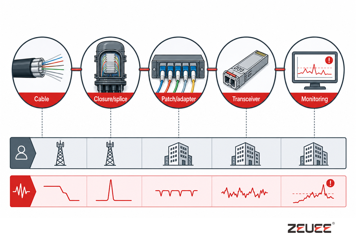
Passive plant and active equipment have different failure signatures and owners. Cable, splice trays, closures, patch panels, adapters, splitters, and connectors need mechanical protection, cleanliness, labeling, and an accessible test path. Transceivers, switches, routers, OLTs, amplifiers, and monitoring platforms add power, thermal, firmware, coding, and interoperability conditions. The FOA installation references are a useful cross-check for passive-plant terminology and test access.
| Role | Interface | Commissioning question | Owner |
|---|---|---|---|
| Cable | Fiber type, count, sheath, bend | Does the route protect the construction? | Plant |
| Closure/splice | Tray, seals, strain relief | Can the splice be identified and re-entered? | Field |
| Patch/adapter | Geometry, polarity, keying | Is mating and inspection repeatable? | Integration |
| Transceiver | Form factor, wavelength, protocol | Does the optic match reach, power and host? | Network/IT |
| Monitoring | Telemetry, alarms, test access | Can operations isolate a physical fault? | Operations |
Translate each interface into a requirement, a test point, and an owner. That discipline will get you farther than a generic “future-proof” statement. Field faults or connector mismatches are easier to contain when the 10 km route, specified connector-geometry check, and IEC 61300-3-35 evidence are attached to the same interface record.
How Do FTTH, 5G Backhaul, Data Centers and Enterprise Links Differ?
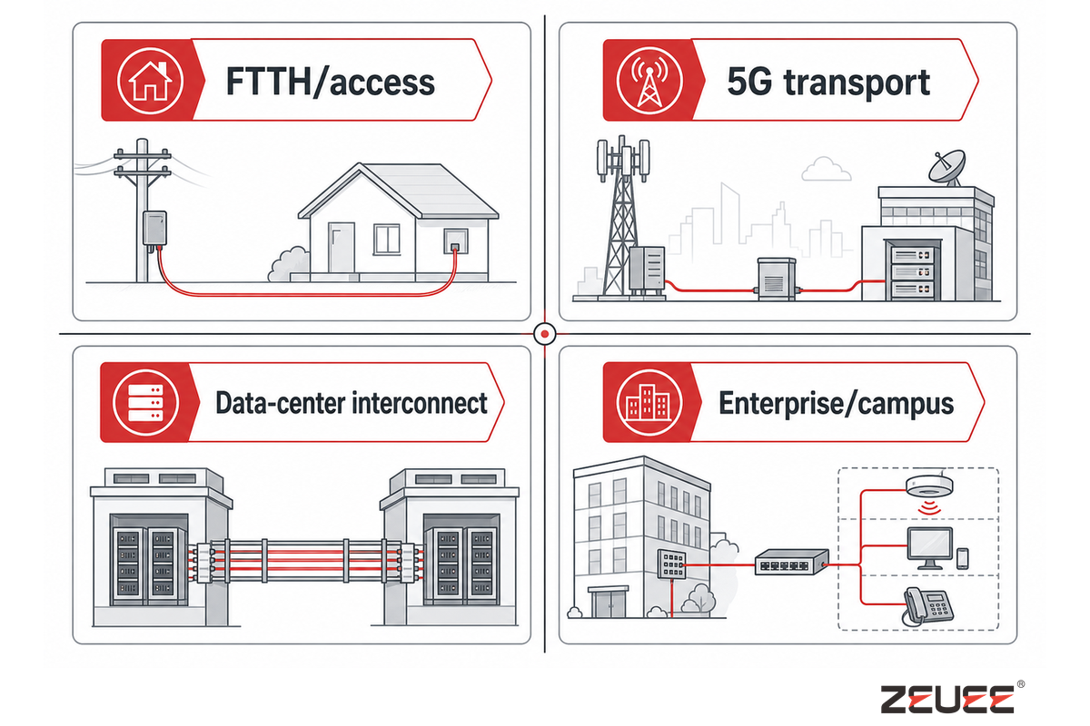
“Fiber optic” describes a medium, not an application. FTTH emphasizes scale, outside-plant access, split architecture, installation productivity, and repeatable activation. 5G transport emphasizes latency, synchronization, route diversity, and outdoor conditions. Data-center interconnect emphasizes density, polarity, thermal limits, optics, and rapid change. Enterprise links emphasize maintainability, documentation, and local troubleshooting. Those interfaces set the application context; current Omdia connectivity data illustrates why application context changes over time.
A peer-reviewed comparison of 5G transport options shows that fronthaul, PON, microwave and millimeter-wave links can have different reach and capacity constraints; use the 5G transport study when an architecture review needs more than a generic fiber label. A 5G work package may also carry operational-security requirements, so treat the NIST NCCoE 5G cybersecurity project as a separate review track rather than assuming optical tests cover the service. One U.S. federal procurement, for example, required resilience against a single fiber-cut event and separate capacity zones for core, interconnect, edge, and storage traffic, per this GAO procurement record.
| Application | Design pressure | Acceptance evidence |
|---|---|---|
| FTTH/access | Scale, splitter loss, field access | Route records, cleanliness, OTDR/OLTS, port map |
| 5G transport | Latency, timing, diversity, outdoor exposure | Path diversity, environment, optic compatibility, alarms |
| Data-center interconnect | Density, polarity, thermal and change velocity | End-to-end loss, labels, optic and port inventory |
| Enterprise/campus | Legacy mix and maintainability | As-built drawing, test pack, spare policy |
Select an application profile in advance of a component family. The same connector can be acceptable in a clean data room and unsuitable in an exposed closure. In a deployment or production handover, compare the 10 km route and the ITU-T G.650.3 test method because a field failure is often an environment or acceptance mismatch, not a bad fiber.
Application choice becomes a risk decision when a migration, data-center expansion, or field repair is involved. Links can fail even when the glass is sound because the optic, polarity, route, and acceptance method were chosen for a different use case. Compare the buyer’s 10 km requirement with the installed environment, record the evidence, and treat any apparent “best” answer as a hypothesis to test.
How Are Fiber-Optic Cables and Telecom Equipment Manufactured?

After the application profile is set, cable manufacturing and telecom-equipment manufacturing share quality discipline but not identical process steps. Cable flow may include drawing, coating, coloring or ribboning, stranding, strengthening, jacketing, testing, marking, and packaging. Equipment or connector work may include stripping, termination, polishing, alignment, inspection, optical testing, labeling, and integration. NIST’s digital-thread guidance is a useful reference for keeping product and quality data traceable across those steps.
Before requesting an automation concept, define the product family, critical characteristics, volume and mix, inspection points, and change control. Show variants, revision-controlled drawings, representative samples, loss and geometry limits, batch size, change-over rate, traceability fields, and the approval path for new optic, connector, cable design, or firmware revision. For a station-by-station view of connector termination itself, see the fiber-optic connector assembly process breakdown.
Manufacturing briefs fail when a stable-looking sample hides variant risk or rework. The root cause is usually an undefined characteristic, not a missing robot. For an illustrative brief, state the geometry field, variant mix, changeover target, inspection method, and evidence owner. Production or procurement reviews can then compare a factory concept with the actual acceptance plan.
Automation is a process-readiness decision before it is an equipment decision. Review the optical connector assembly line for process context and learn about ZEUEE, an automation-equipment builder, for company context — a 20,000 sqm operation with 120+ staff, ISO 9001:2015 certification, 150+ patents, and customers in 30+ countries — but do not substitute a company profile for your drawings, samples, acceptance limits, or change-control records. The same evidence should be readable by engineering, quality, operations, and telecommunications teams.
Which Tests Prove a Link Is Ready for Handover?

Ready links need more than one optical power reading alone. Reproducible handovers combine connector inspection, insertion or return-loss evidence, OTDR fault-location records, and polarity or continuity confirmation. Each record names the link, method, instrument, limit, result, exception, and release owner. The FOA testing references describe the practical distinction between inspection, loss testing, and fault-location work.
For optical-transport or active-equipment acceptance, check whether ITU-T O.182 error-performance assessment or ITU-T G.798 equipment-layer checks also apply; the Handover Evidence Quartet is a physical baseline, not a universal service acceptance rule.
In U.S. Rural Utilities Service-financed telecommunications-plant work, 7 CFR 1755.404 requires bidirectional splice-loss measurements at 1310 nm and/or 1550 nm. When the construction contract sets no limit, the rule caps each field splice at 0.2 dB and each central-office splice at 1.2 dB. ITU-T G.650.3 likewise cautions that precise splice-loss assessment may require bidirectional measurement.
Handover Evidence Quartet
A single optical power measurement isn’t evidence of all failure modes. The Handover Evidence Quartet removes guesswork by defining a repeatable set of checks that a technician can run again in the future.
| Test | Proves | Minimum record | False comfort |
|---|---|---|---|
| Visual inspection/cleaning | Interface is clean, undamaged, keyed and capped | Microscope pass/fail, tool and connector ID | “It looked clean” without magnification |
| Insertion/return loss | End-to-end loss and reflection meet the method | Reference, wavelength, calibration, result, limit | Generic limit that ignores connectors/splices |
| OTDR fault location | Events, reflections and route distance are explainable | Launch/tail, trace, event table, route reference | Using OTDR as a substitute for loss testing |
| Polarity/continuity | Transmit and receive paths land on intended ports | Port map, method, endpoint IDs, exceptions | Assuming labels survived a repair |
Include as-built drawings, enclosure photographs, optic identifiers, calibration information, environment checks, and a release signature when applicable. When a result fails, preserve the original trace, re-inspect and clean, confirm polarity, isolate the segment, compare the event with the drawing, and then test the suspected component. See automated testing equipment for related production-test context.
Use project-specific values rather than assumed defaults: an illustrative record might show a 10 km route, 1310 nm and 1550 nm tests, 37°C ambient, a 5 mm bend check, a 20 m enclosure offset, a 24 hr retest window, and a 99.9% service target. The applicable standard and contract must set the real limits.
What Fails in Fiber Optics & Telecom Deployments?
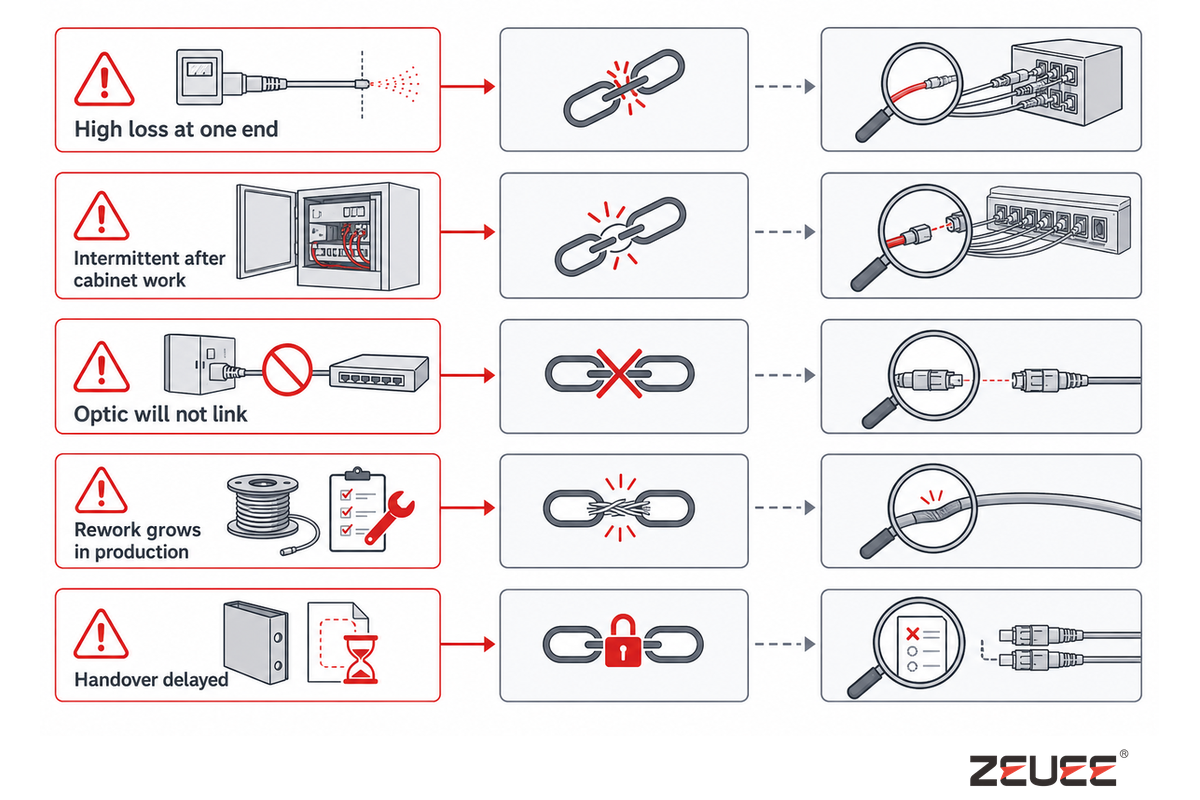
Many repeat faults are interface failures rather than failures of the glass. Contamination adds loss; an over-tight bend creates intermittent behavior; a polarity mistake creates a dead link; a coded-optic mismatch looks like a plant failure; poor splice protection turns a good test into a future repair. Check the evidence chain before replacing the most expensive component; the FOA fiber-testing references support that troubleshooting order.
| Observed issue | Hidden constraint | First evidence | Owner |
|---|---|---|---|
| High loss at one end | Dirty/damaged connector or bad reference | Inspection and controlled retest | Commissioning |
| Intermittent after cabinet work | Bend, polarity or patching change | Photos, port map, OTDR comparison | Field/integration |
| Optic will not link | Wavelength, coding, firmware or reach mismatch | Part numbers, host compatibility, alarms | Network/IT |
| Rework grows in production | Variant mix or unclear characteristic | Defect Pareto by variant and station | Manufacturing/quality |
| Handover delayed | Records owned by nobody | Missing IDs, calibration, signature | Project manager |
Contain first: protect live service, preserve the original trace, identify the affected population, and record the temporary action. Correct process or design second. When discussing a supplier, include the observed fault, population, route or station context, previous evidence, and questions to be decided.
How Should a Buyer Specify a Fiber-Optics or Telecom Work Package?
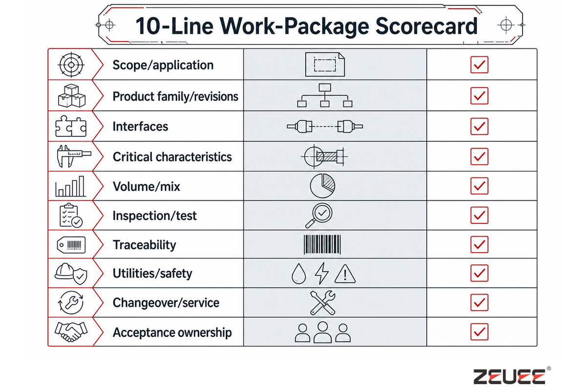
Suppliers cannot responsibly size a process or automation concept from a throughput target alone. Score each line below as 0 (unknown), 1 (partly defined), or 2 (evidence attached). Concept reviews are ready when no critical line is zero and the acceptance owner is named. IEC’s standards catalogue is a reminder to name the exact adopted test or product standard rather than citing “IEC” generically.
10-Line Work-Package Scorecard
| Category / scorecard line | Evidence to attach | Critical? |
|---|---|---|
| Scope/application | FTTH, backhaul, DCI, enterprise or production; topology and geography | Yes |
| Product family/revisions | Drawings, variants, samples and identifiers | Yes |
| Interfaces | Mechanical, optical, electrical, software and data owners | Yes |
| Critical characteristics | Loss, geometry, retention, cleanliness and labeling limits | Yes |
| Volume/mix | Demand by variant, batch, takt and peak scenario | No |
| Inspection/test | Method, wavelength, reference, calibration and release rule | Yes |
| Traceability | Serial/lot model, fields, retention and export | Yes |
| Utilities/safety | Power, air, network, guarding, access and maintenance envelope | Yes |
| Changeover/service | Variant logic, spares, training and escalation | No |
| Acceptance ownership | Named approver, FAT/SAT evidence and exception path | Yes |
Share the scorecard across engineering, quality, operations, IT, and procurement. Any mismatch between these departments is a design input that needs resolution before a quote can be issued. If a supplier brief still carries a risk or an unclear acceptance limit, add the 10 km example, the IEC 61300-3-35 method, and the specified geometry field before treating the document as evidence.
For an illustrative, repeatable production trial, state an operating envelope such as 2 variants, a 15 min changeover, an 8 hr shift, a 12-month calibration interval, 100% visual inspection, a 0.2 mm geometry limit, 48 V supply, and 2 kW available power. For site acceptance, record a 30 min stabilization window, a 6-month review cadence, a 15°C temperature delta, a 1 m access clearance, and a 0.1 mm inspection resolution if those constraints matter. These are project fields to confirm, not universal specifications.
For equipment-side examples, compare those inputs with the fiber-optic connector assembly machine instead of assuming one standard configuration fits every work package.
What Is Changing in Fiber Optics & Telecom in 2025–2026?
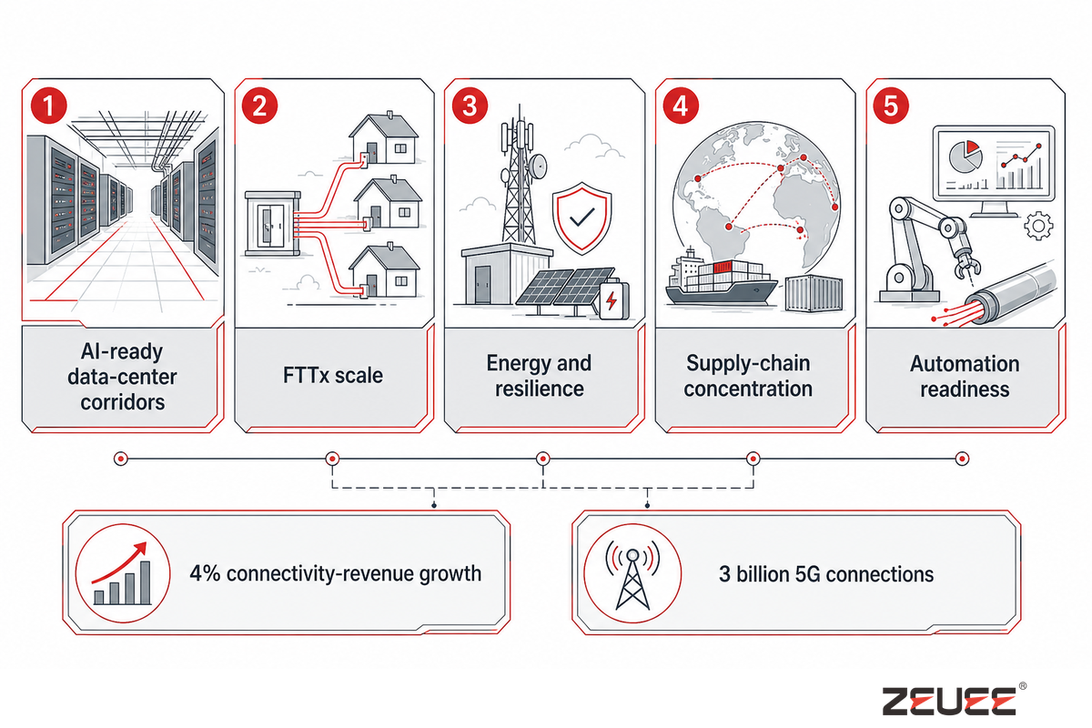
With that work package defined, current sources point to drivers, not one universal forecast. Omdia’s 2026 update reports 4% connectivity-revenue growth in 2025 and more than 3 billion 5G connections. CRU’s 2025 optical-fibre work highlights shifts in demand, capacity, and data-center forecasting. PwC’s 2026 outlook emphasizes capacity, resilience, economics, and energy. The EU Digital Decade report adds a policy and coverage lens. Translate those signals into project questions, starting with the CRU optical-fibre industry update as dated context:
- AI-ready data-center corridors: ask for density, thermal, polarity, transceiver, and change-window evidence—not only more fiber count.
- FTTx scale: ask how route records, cleanliness, split loss, activation, and technician training scale.
- Energy and resilience: ask which active devices, cooling assumptions, and route-diversity choices change operating risk.
- Supply-chain concentration: ask for approved alternatives, revision control, and a test plan for material changes.
- Automation readiness: ask whether critical characteristics and traceability are stable before buying a station.
For every trend, show source date, geography, metric definition, driver, buyer implication, and uncertainty. Market numbers are context—not promises about one region, plant, or supplier.
The practical risk is stale or overclaimed context: a 2025–2026 signal can change by geography, metric, and supply position. Because a buyer may translate a headline into a route or production decision, keep the source date, unit, baseline, and uncertainty beside the number.
How Do Teams Turn the Guide Into a Repeatable Project Brief?
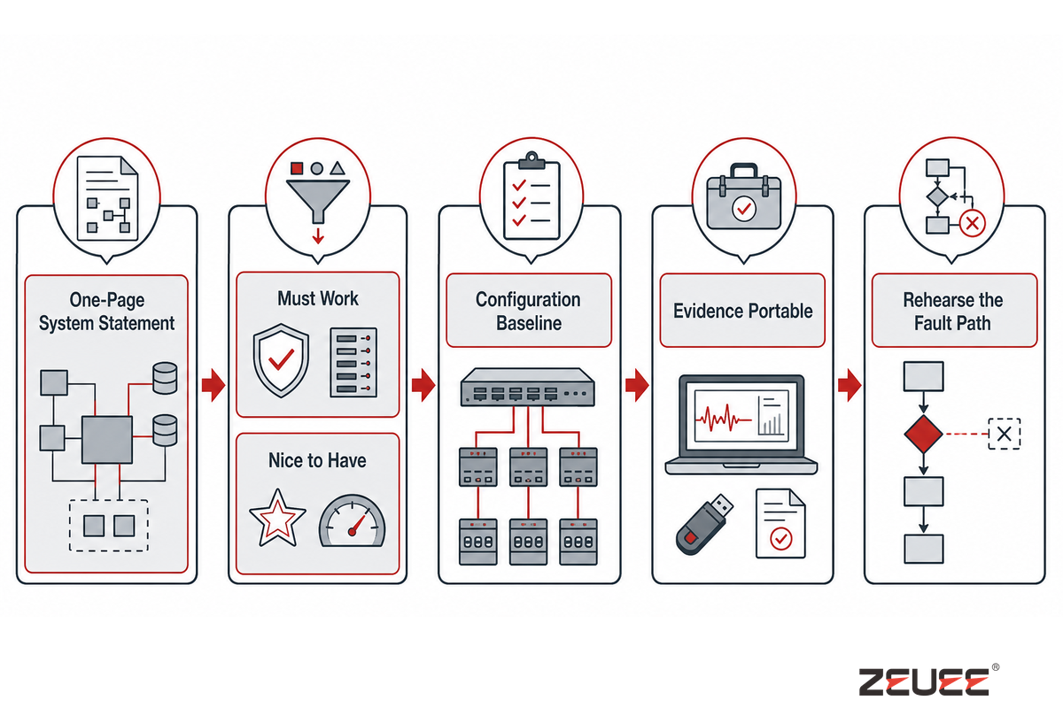
After recording that uncertainty, start with a one-page system statement. Name the application, endpoints, route or station boundary, expected service, and the person who can approve an exception. Then attach the layer map and scorecard. This makes an early design review concrete without pretending that every parameter is already known. Unknowns become dated actions with an owner, not hidden assumptions in a supplier spreadsheet. That traceability principle aligns with NIST’s manufacturing digital-thread reference.
Next, separate “must work” from “nice to have.” Must-work items have measurable characteristics and release methods: optical loss at a named wavelength, connector geometry, bend or temperature limits, a port map, or a traceability field. Nice-to-have items can be evaluated after the baseline route or process is stable. This separation protects the project when budget or schedule pressure arrives.
Use a configuration baseline. Record the drawing revision, cable construction, connector family, optic identifier, firmware or coding assumptions, test reference, and approved alternatives. When something changes, compare the new item against the baseline and decide whether a partial or full retest is needed. Change records are faster than tracing a silent mismatch after a cabinet has been repatched.
Make evidence portable. Handover records should not depend on one engineer’s laptop or a screenshot with no link ID. Store the raw trace, the summarized result, the instrument and calibration identity, and the acceptance rule together. For production, link records to a lot, serial, variant, station, and operator or recipe revision. For deployment, link them to the route, enclosure, port, and date.
Plan spares from failure modes, not from a generic percentage. Spare optics help only when coding, wavelength, host, and reach are compatible. Spare patch leads help only when connector polish, polarity, and length fit. Replacement closures help only when the team has a re-entry and retest procedure. List the evidence needed to release a spare so operations does not trade one uncertainty for another.
Finally, rehearse the fault path. Give a technician a deliberately incomplete fault report—high loss, intermittent link, or missing port—and ask which record they open first. If the answer depends on tribal knowledge, improve labels, diagrams, monitoring, or the handover pack. Resilient fiber-optics and telecom systems make the next troubleshooting action obvious and safe.
FAQ: Fiber Optics & Telecom
Is fiber optic the same as telecom?
No. Fiber optic is a transmission medium and its optical components, while telecom is the service and network system that also includes copper, radio, satellites, active electronics, software, and operations. Fiber routes can support access, mobile backhaul, data-center interconnect, or enterprise links. The design task is to fit the optical layer, active equipment, and service requirements together. That distinction matters when a buyer defines scope, ownership, test evidence, and the boundary between passive plant and active network service.
What is the difference between fiber optics and fiber-optic cable?
Fiber optics describes how a light signal travels through a glass waveguide, while fiber-optic cable is the physical product that packages one or more fibers with coatings, strength members, fillers, water blocking, armor, or a jacket. Cable construction determines how the fiber can be pulled, bent, protected, terminated, repaired, and tested. Similar glass does not mean identical mechanical or environmental behavior.
Which tests should be in a fiber handover pack?
A handover pack should include visual inspection and cleaning evidence, insertion/return-loss results using a named reference method, OTDR event records, and polarity/continuity confirmation. Add route records, enclosure photos, optic identifiers, calibration details, environmental checks, and an exception signature where required. Each record names the link, instrument, method, limit, result, and release owner.
When does automation become useful in fiber-optic or telecom production?
Automation helps once product variants, interfaces, critical characteristics, tests, changeover logic, and traceability are stable. If drawings or acceptance rules are still changing, automation can repeat ambiguity faster. Start with representative samples and an acceptance plan before choosing a station or locking a recipe.
References & Sources
Testing a live deployment should follow the applicable local regulations and project-specific standards. This guide uses the following public reference points:
- ITU-T G.652, G.657, O.182, G.798, and G.650.3
- Fiber Optic Association technical and testing reference library
- 7 CFR 1755.404 (USDA Rural Utilities Service telecommunications construction standard)
- IEC 61300 series (fibre-optic interconnecting devices and passive components — basic test and measurement procedures)
- Omdia connectivity update
- CRU optical fibre and cable shifts
- PwC telecom outlook
- EU Digital Decade connectivity report
Ready to turn project requirements into a production discussion?
Review the fiber-optics and telecom industry solutions page, then use the site’s consultation prompt (#ct-popup-793) with your product family, samples, critical characteristics, and acceptance plan. Keep the commercial page focused on configuration and fit; keep this guide as the shared decision reference.
WHY WE WRITE THIS
About ZEUEE Engineering Insights
ZEUEE shares technical guides based on real automation project experience. Since 2005, we have designed and manufactured non-standard automation equipment for connector assembly, wire harness production, robotic lines, vision inspection, and smart factory upgrades.
Founded in 2005
20,000 m² production base
120+ specialists
150+ R&D patents
ISO9001:2015 certified







![Automated Screwdriving: Torque & Cycle Time [Guide]](https://zeueeauto.com/wp-content/uploads/2026/10/automated-screwdriving-featured-150x150.png)


