Get in touch with Zeyu lntelligent Industrial Company

Twist Pin Cutting & Welding Machine: Engineering Guide to Wire Preparation, Tip Fusion, Vision QA, and Capacity Sizing

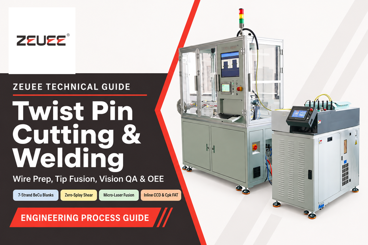
A Twist Pin Cutting & Welding Machine fabricates 7-strand beryllium-copper helical contact blanks for 0.050-inch (1.27 mm) MIL-DTL-83513 connectors. It meters fine cable from a spool, shears it to length, and fuses the ends of the pins with a laser. Construction stud welders, steel rebar choppers, and plasma cutters serve completely different metalworking lines.
Updated November 2026 · By Cherry
Engineering Scope at a Glance
- Target Blank: Seven-strand copper-alloy helical spring pin contact per MIL-DTL-83513 and Nano-D derivatives.
- Core Operations: Constant-tension payoff, two-plane wire straightening, zero-splay shear cutting, and millisecond micro-laser tip fusion.
- Critical Risk: Wide thermal input over-ages beryllium copper, whereas uncaptured outer strands cause open caps and sleeve jams.
- Qualification Rule: Inline optical vision pairs with destructive tensile pull testing, cross-section metallography, and OSHA HEPA extraction.
A Twist Pin Cutting & Welding Machine produces precision multi-wire spring contacts for aerospace and defense interconnects. Reliable cell operation requires narrow heat-affected zones, rigid strand-capture collets, optical and pull verification, and explicit OEE changeover tracking.
What Does a Twist Pin Cutting & Welding Machine Fabricate vs. Generic Wire Cutters and Stud Welders?
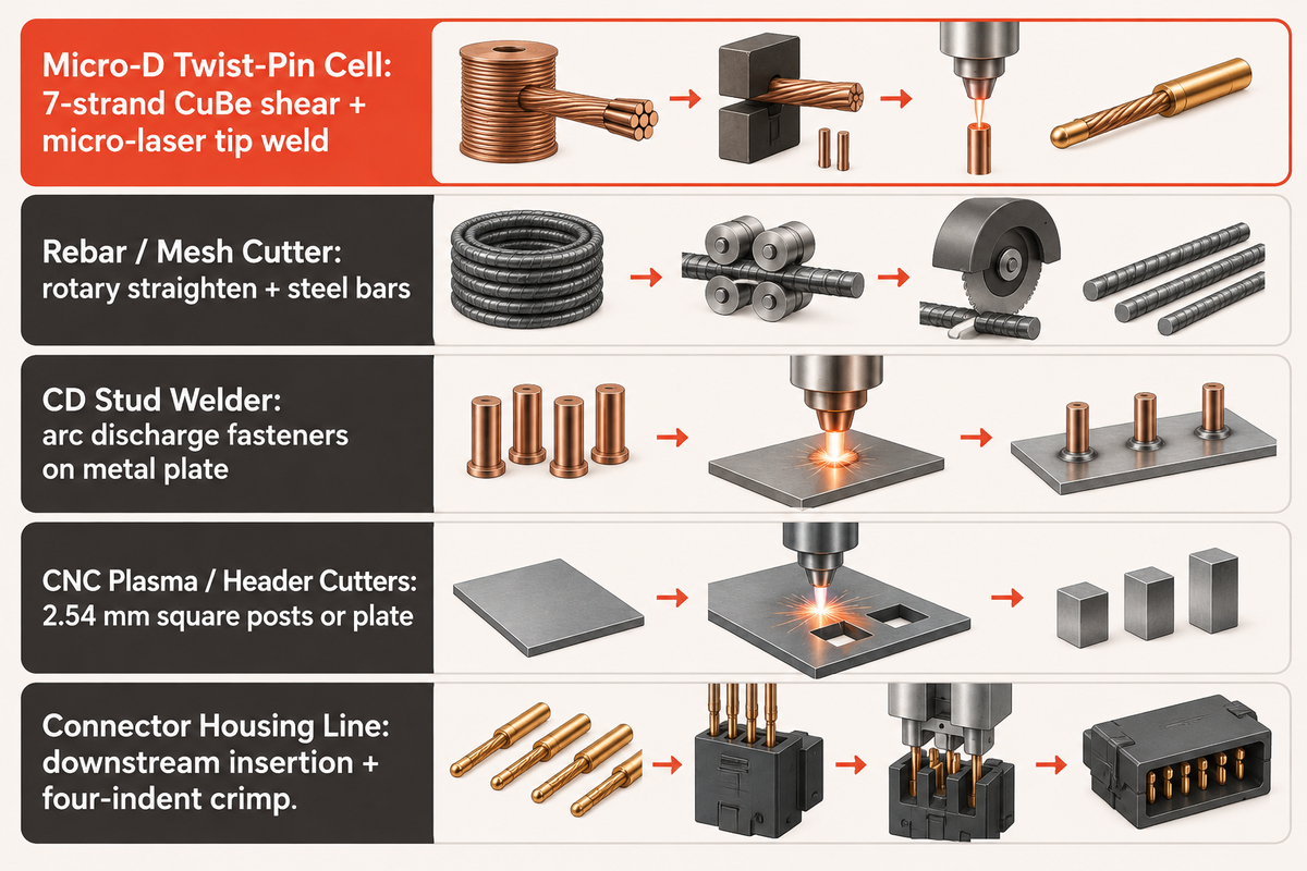
A connector twist-pin machine processes sub-millimeter braided copper alloys into burr-free contact blanks with fused tips. Generic wire choppers, construction stud welders, and industrial cutters process heavy ferrous wire or sheet metal. Mixing these machine categories leads buyers to wrong tooling quotes and failed trials.
Demos and search results sometimes blend together miniature connector manufacturing with entirely different processes. Broad search terms often bring up automated wire straightening and cutting systems built to create steel rebar mats. Other top results show CNC plasma cutting tables, sheet bending machine tools, or capacitor-discharge stud guns.
None of those heavy machinery systems handle miniature beryllium-copper bundles. Wire mesh welding lines and 2D flat wire bending frames feed thick iron, steel, or aluminum wire. Bulk pin-header choppers slice solid, square brass posts at 2.54 mm center-to-center without melting stranded ends.
In truth, a dedicated system to produce twist pins is upstream from finished housing lines. ConnectorSupplier documents that each MIL-DTL-83513 twist pin is comprised of seven wires welded together. Military Embedded notes that Micro-D connectors have 0.050-inch (1.27 mm) contact centers, and are polarized. Therefore, single contact pin fabrication is upstream from connector termination.
| Machine Class | Feedstock & Alloy | Primary Joining or Severing Action | Typical Output Component |
|---|---|---|---|
| Micro-D Twist-Pin Cell | Helical 7-strand CuBe or phosphor-bronze cable | Dual-jaw pinch shear plus micro-laser tip weld | Domed contact blanks ready for crimp sleeves |
| Rebar / Mesh Straightener & Cutter | Millimeter steel, iron, or aluminum single wire | Rotary-flyer straighten plus high-force shear | Straight bars or welded wire mesh panels |
| Capacitor-Discharge Stud Welder | Solid weld studs on steel or aluminum plate | High-current arc discharge against base sheet | Anchored structural metal fasteners |
| CNC Plasma & Pin-Header Cutters | Metal plate or molded square header strip | Thermal plasma kerf or gang block-shear slice | Cut plate profiles or segmented header rows |
| Full Connector Housing Line | Pre-made pins, sleeves, insulators, shells | Pin insertion, four-indent crimping, shell check | Finished QPL Micro-D cable assemblies |
Downstream connector assembly factories treat welded twist pins as finished incoming hardware parts. Buyers who bring bulk blank manufacturing in-house install specialized wire-preparation cells ahead of crimp stations. Inspect proprietary 0.45 C49-ZY04-01 specs, 4 subsystem cards, and interactive selectors on ZEUEE’s Twist Pin Cutting & Welding Machine commercial solution page. This guide focuses instead on cross-process laser, TIG, and resistance failure physics plus 3-loss OEE math.
How Twist-Pin Helical Mechanics, MIL-DTL-83513 Centers, and Beryllium-Copper Metallurgy Set Machine Limits
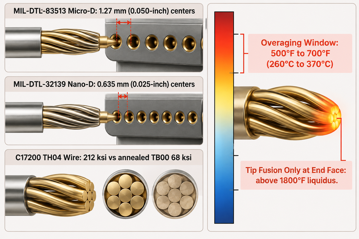
Principles of contact mechanics and alloy sensitivity to precipitation hardening determine the thermal and mechanical limits in every cell. Seven-wire bundles depend on spring tension to close contact pairs in Micro-D (0.050-inch) and Nano-D (0.025-inch) cavities. Excessive weld heat ruins spring elasticity before blanks even leave the machine.
Multi-strand male contacts were introduced by the USPTO Patent US3258736A (1966) granted to IBM. That design winds spring strands helically around a central core wire. Modern twist pins bow slightly outward across their active waist. When a bowed pin is inserted into a socket, the seven strands are radially compressed to make contact.
The contact pairs have narrow physical limits. Interface standards set the requirements. DLA ASSIST lists MIL-DTL-83513 Revision H Amendment 2 dated September 13, 2023, as the Micro-D general specification. Military Embedded contrasts 1.27 mm (0.050-inch) Micro-D centers with tighter 0.635 mm (0.025-inch) MIL-DTL-32139 Nano-D layouts. A cited standard-density D-sub part uses 2.77 mm spacing and thick machined pins.
Thermal limits on alloys create even tighter process windows. Copper Development Association tables for wrought C17200 beryllium copper specify 1.80% to 2.00% beryllium and 22% IACS conductivity. Its solidus starts at 1590°F and liquidus reaches 1800°F. Hard, precipitation-treated TH04 wire hits 212 ksi typical tensile strength, whereas annealed TB00 wire drops to 68 ksi.
Materion heat-treating data pinpoints precipitation aging between 500°F (260°C) and 700°F (370°C). At 700°F, dwell time holds a tight plus or minus 3-minute tolerance before overaging softens the alloy. Standard 600°F (315°C) aging takes 2 to 3 hours, while full solution annealing hits 1450°F (790°C). Tip fusion must cross 1800°F right at the end face without annealing the active spring bulge immediately behind it.
The order of finish processes also affects weld behavior. ConnectorSupplier acknowledges Materion Alloy 290 with Cinch Dura-Con welded tip pins and ASTM B-194 strips. Welding bare copper-beryllium prior to a nickel barrier and barrel gold plating stops gold boil-off in the weld pool. Pre-plated wire requires more precise energy control to avoid nickel-gold metallic spatter.
Why do twist pin contacts require tip fusion instead of bare cut wire strands?
Shearing multi-strand wire without fusing the cut face leaves loose, sharp outer filaments. A welded hemispherical cap locks all seven strands of wire into a single rigid dome. That rigid dome slides effortlessly into the female plated sockets without gouging the gold barriers or collapsing the helix.
Stored helical torsion pushes severed outer wire strands outward right after blade release. This distortion is called birdcaging by techs. Even slight strand flare makes the tip larger than the socket entry chamfer and buckles the pin during insertion.
Constant-Tension Payoff, Two-Plane Straightening, and Shear-Cut Tooling Physics
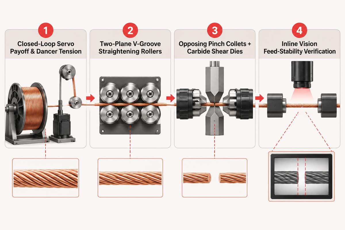
Stable welding starts at the wire reel and the carbide shear. Erratic unwind drag stretches miniature stranded cable and skews encoder feed length. Worn shear dies extrude burrs and untwist outer filaments right where laser focus demands tight contact between wire strands.
Aerospace wire coils feature thin, helical strands that exhibit a strong response to dereeling inertia spikes. For comparison, check stamped flat-contact specs, such as Alloy 290 strip, which can be formed to as little as 0.002 inches (0.05 mm) in thickness. During indexing stops, passive payoff spindles jerk: back-tension surges tug directly on a wound wire lay.
Closed-loop servo payoff frames maintain constant tension. Responsive servo motor and dancer drive systems work together to provide steady torque. Next, wire passes through two-plane V-groove roller guides. Unlike aggressive rotary-flyer straighteners built for solid steel rod, multi-roller banks gently remove coil curvature. Tension feedback loops log drift directly inside machine control software for batch traceability.
Prior to cutting, high resolution encoders provide tight tolerance measurements on servo pinch capstans. Downstream connector termination tolerances stay tight on small assemblies, such as soldered MIL-DTL-83513 rear cups terminating 26 AWG conductors. Similarly, UTMEL’s connector failure analysis notes for downstream crimping that clean, un-nicked bare conductor strands must remain throughout the effective crimp barrel. Operators who skip edge checks on blade tools often mistake burr scatter for phantom laser beam energy shifts.
The way the wire bundle holds its shape relies on the mechanical clamping adjacent to the cut plane. External prior art in USPTO Patent US7775841B2 (assigned to QA Technology, separate from twist-pin blanking machinery) shows multiple wire sockets being captured by grooved rotary mandrels and laser welded. Rigid opposing collets on twist-pin blank cells grip both sides of the carbide path during shear and the following weld steps. An inline vision system verifies feed stability right as the wire cutting step is completed.
How do payoff tension drift and shear blade wear trigger downstream weld defects?
Pitch variation caused by inconsistent back tension of the spool alters effective strand pitch and affects final blank length during indexing. Dull shear inserts smear copper burrs and kick single outer wires radially off center. Misaligned strands sit outside focused beam cores and solidify into irregular, weak weld balls.
Even a hair-width gap breaks thermal conduction across adjacent copper strands. Focused optical pulses then vaporize or ball the stray outer filament instead of melting the whole bundle together. Scheduled carbide die swaps halt bead eccentricity.
Micro-Laser vs. Micro-TIG vs. Resistance Fusing for Twist-Pin Tip Welding
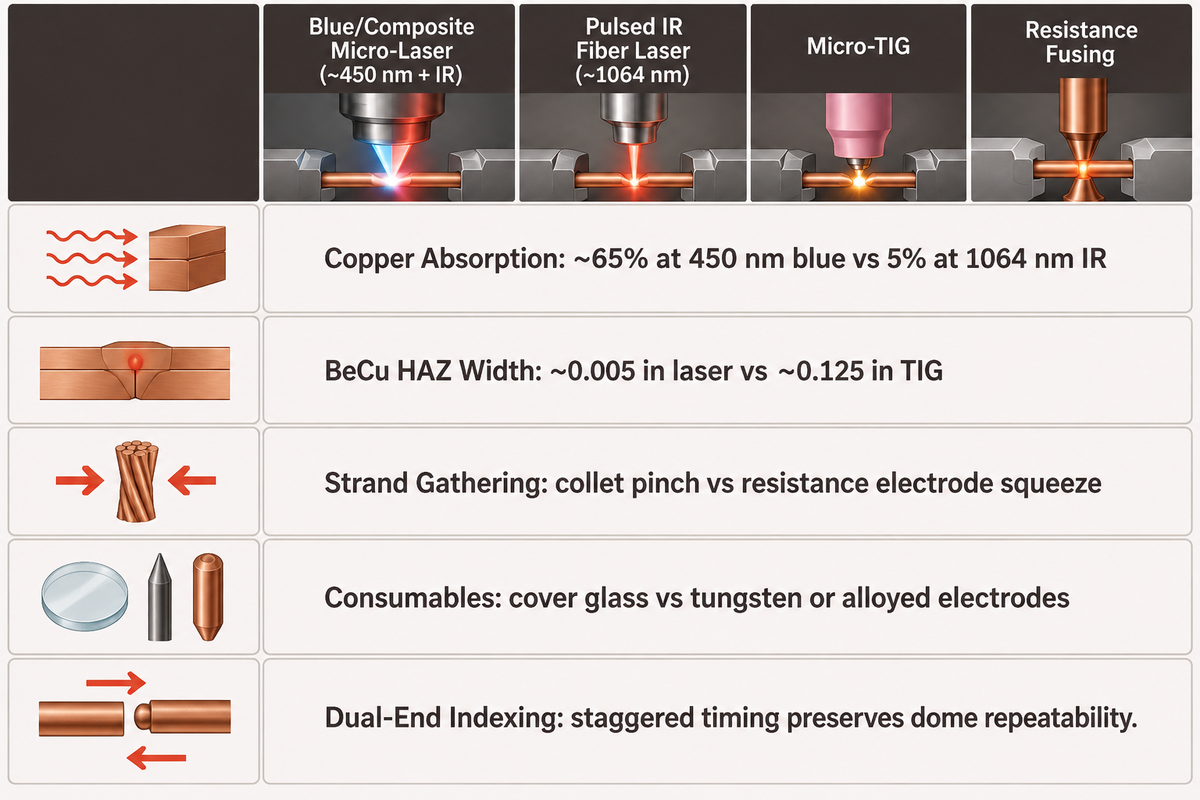
Balancing copper reflections with thermal confinement and mechanical compression requires selection of an appropriate tip-fusing energy source. Pulsed micro-lasers give better process control and tight-seal weld compared to TIG-plasma. Noncontact optical beams, however, apply zero squeeze force to pull loose filaments back toward the center wire.
Wavelength choice strongly governs copper melting predictability. Iqbal & Sadeghian (ScienceDirect, 2023) report 65% laser absorptivity on solid copper at ~450 nm blue wavelengths compared to 5% at ~1064 nm IR. That 13x absorption increase lowers power spikes that trigger spatter when melting reflective metals.
Thermal comparisons of optical and arc techniques show considerable differences. Phoenix Laser measured shop thermal differences on beryllium-copper tooling repairs. Precision laser pulses were reported to have a heat affected zone (HAZ) of 0.005 inches. TIG (welding) expanded the HAZ to 0.125 inches, 25x the size, under the same working conditions.
Composite beam designs allow for greater copper joining speeds. Han’s Laser US (2026) tested red-blue composite systems combining ~450 nm blue initiation with IR penetration on fine copper connector leads. Weld shapes stayed uniform while holding tensile pull above 30 N against a 20 N spec. Meanwhile, Choi et al. (NIH PMC, 2026) compare laser and resistance copper joining. Lasers eliminate electrode wear and keep distortion tiny under tight wire fit-up. By contrast, resistance tips squeeze loose wires shut while wearing rapidly from copper alloy sticking.
When using laser vs. TIG, shielding gas discipline is also shifted. The broad plasma arc of a TIG can melt the thin gold finish away from the dome and impact adjacent copper. Focused micro-lasers can align coaxially with the argon stream to couple cleanly on the sheared dome face. Proper nozzle flow keeps oxygen below discoloration levels and protects the cover glass from spatter.
There are also practical limits to the use of optical motion control. Kitagawa et al. (ScienceDirect, 2026) analyze beam oscillation shapes such as straight, circular, and figure-eight. They say that increasing the amplitude of oscillation isn’t always the right solution to laser welding problems. Too wide a sweep of the oscillating beam can concentrate thermal strain at the edges of the weld.
Copper-Bundle Tip-Fusion Trade-Off Matrix
| Engineering Parameter | Blue / Composite Micro-Laser (~450 nm + IR) | Pulsed IR Fiber Laser (~1064 nm) | Micro-TIG (Pulsed Plasma Arc) | Opposed-Electrode Resistance Fusing |
|---|---|---|---|---|
| Copper Optical Coupling | High (~65% solid Cu absorption at 450 nm) | Low (~5% solid Cu absorption; spike sensitive) | Surface reflectivity agnostic (arc heated) | Bulk Joule resistive heating across strand gaps |
| BeCu Spring HAZ Control | Very narrow (ms pulse control with chill jaws) | Narrow (~0.005 in empirical benchmark class) | Wide (~0.125 in empirical shop comparison) | Moderate; electrode thermal mass sinks heat |
| Loose Strand Gathering | Zero squeeze force; relies strictly on pinch collets | Zero squeeze force; strict cut splay ceiling | Zero mechanical squeeze; wide arc bridges gaps | Active mechanical squeeze force compacts wires |
| Consumables & Uptime | Noncontact optics; clean protective cover glass | Noncontact optics; back-reflection isolator required | Tungsten electrode erosion requires grinding | Electrode tip wear, alloying, frequent dressing |
| Dual-End Indexing Risk | Consistent dome geometry at both pin ends | High power ramp needed to start initial melt | Sensitive to tip length gap and gas draft | Shunt current drift if fixtures accumulate oxide |
Which joining trade-offs keep heat out of the beryllium-copper spring bulge?
Pulsed millisecond bursts, gripping the wire shank within water-cooled copper jaws, keep the spring waist from heat soaking. Laminar argon sheath flow prevents surface oxidation and keeps the outer filaments undisturbed. Welding bare wire ahead of the final plating preserves the shape of the weld.
Dual-end cells stagger sequential weld timing so front and rear thermal fronts never overlap. Limiting total energy input keeps heat well below the 500°F to 700°F overaging threshold to preserve spring modulus.
Inline CCD Machine Vision, Weld-Defect Diagnostics, and Pull/LLCR Verification
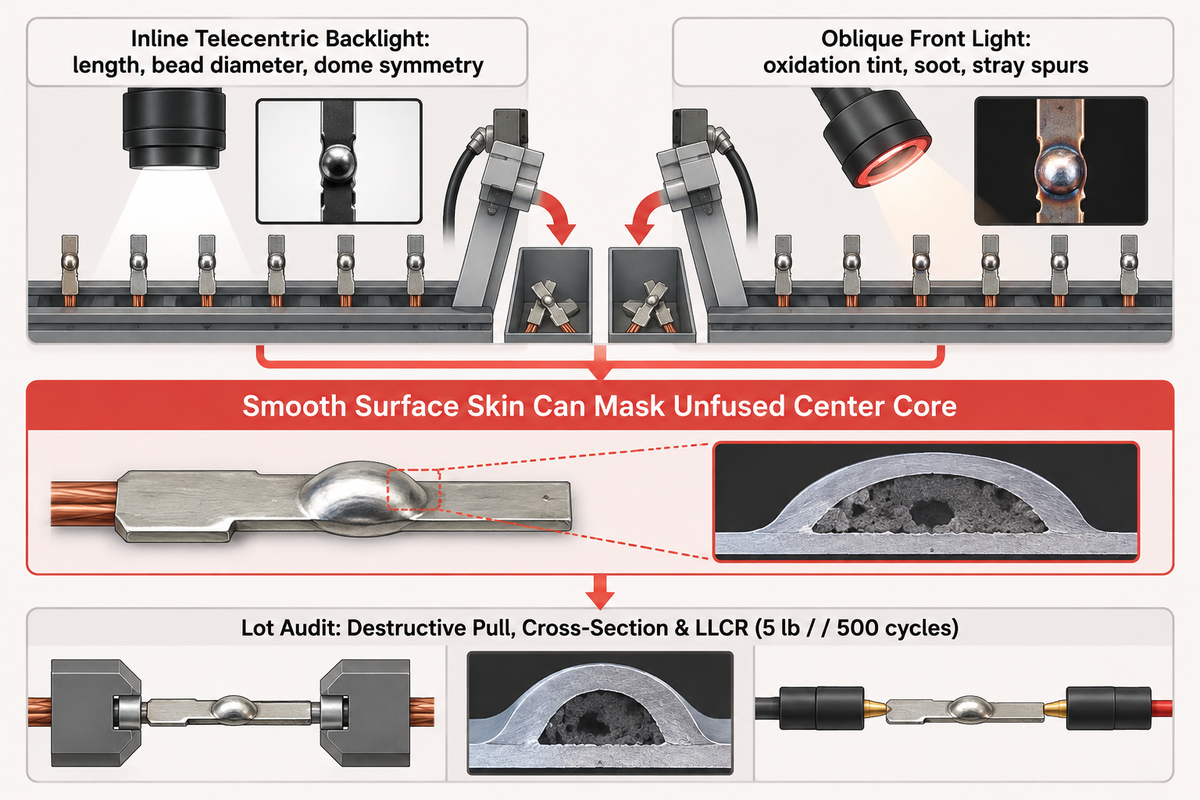
A continuous, inline CCD optical camera checks the symmetry and length of every blank. It also checks the blank for surface cleanliness. Yet, these external checks aren’t able to discern if welds are cold bonded. True process qualification couples automated optical sorting with destructive contact resistance and tensile tests.
Automated blank cells mount machine vision cameras telecentrically, directly downstream of welding stations. High-contrast backlight paths assess cut length repeatability, weld bead diameter versus bore of mating sleeves, and dome symmetry. Oblique front lights catch oxidation discoloration, soot, and unmelted wire spurs.
Quality teams must separate exterior surface screening from structural weld validation. The presence of gross volumetric voids in an assembly can be detected by surface optics, or X-ray radiography. However, NASA JSC notes in MSC-TOPS-106 that X-ray checks still show low probability of detection on tight internal cracks. A smooth surface skin on copper alloy tips can mask an unfused center core.
Optical checks, early in the assembly process, can catch defects downstream. An oversized dome collides with the lead in of the socket in multi pin housing blocks. A surface whisker, bent laterally under crimping punches, can drop insulation clearance margins. Calibrated sub-pixel camera triggers drive pneumatic reject chutes to eject defective parts in single-millisecond sorting cycles.
UTMEL reports that finger tugs and quick checks miss hidden internal voids in termination testing. Preparation zones along contact lengths must be clean and un-nicked to bare metal. Citing NASA/Goddard 20220017466, across 780 pull test samples, properly compacted wire joints achieve more than double the minimum IPC/WHMA-A-620 requirements. Wide statistical margins quickly distinguish centered tooling processes from drifting tooling.
Consistent connector qualification also enforces mechanical and electrical lot audits. Teams sample pins for destructive pull breaks, cross-section polished welds under microscopy and verify LLCR. ConnectorSupplier benchmarks MIL-DTL-83513 qualification limits at 500 mating cycles minimum, 10 ounces times contact count maximum mating force, and 5 pounds minimum contact retention. Explore additional modular camera layouts in ZEUEE’s guide to connector inspection automation manufacturers.
Spool-to-Sleeve Cut & Weld Diagnostic Ledger
| Defect Class | Physical Root Cause | Upstream Detection Method | Corrective Station Action |
|---|---|---|---|
| Strand Splay / Birdcaging | Wide shear jaw gap or untwisted coil memory | Telecentric silhouette width spike at cut face | Re-gap pinch collets and re-balance servo payoff |
| Oversized Weld Ball | Excess pulse energy or prolonged laser dwell | CCD tip diameter alert above sleeve bore limit | Trim ms pulse energy and verify focus spot height |
| Eccentric Dome Alignment | Off-axis laser spot or crooked wire clamp | Backlit tip-to-core coaxial centerline check | Re-zero optical nozzle relative to V-groove jaws |
| Unfused Core Under Smooth Cap | High copper IR reflection stalling deep melt | Hidden from CCD; caught by pull and cross-section | Adopt ~450 nm blue pre-melt under inert shielding |
| Oxidized & Pitted Tip Surface | Argon purge drop or lubricant film on spool | Oblique front-lit dark tint and roughness score | Inspect gas regulator pressure and wipe rollers |
| HAZ Spring Bulge Collapse | Thermal soak exceeding 700°F aging tolerance | Contact retention force failure at mechanical gauge | Increase water-chilled jaw clamping pressure |
| Encoder Cut-Length Drift | Capstan roller slip or payoff tension surge | Full-frame optical length calibration tracking | Clean pinch wheels and retune servo dancer loop |
| Shear Burr Extrusion Lip | Chipped or dulled tungsten-carbide blade edge | Sub-pixel corner flare alarm before welding | Swap replaceable shear blade cartridge cleanly |
| Pre-Plated Gold Boil Porosity | Low-boiling gold plating vaporized at weld tip | Spatter blowout dots on cover glass and pin cap | Cut and fuse raw BeCu prior to barrel plating |
Why does sampling-based manual inspection miss intermittent cold welds in twist pins?
Intermittent weld defects often correlate with brief disruptions as in an oil spot along a wire spool or sudden turbulence from an argon nozzle. Manual sampling easily skips intermittent cold welds and oversized beads in rapid automated runs. Inline optical CCD inspection screens external dome geometry on every pin before downstream tooling while destructive pull checks catch cold welds.
Automated vision cameras, while significantly reducing the need for destructive lot sampling, haven’t completely replaced them. Operators pull tensile test pins after every coil splice or parameter shift to verify accurate deep internal fusion.
Downstream Sleeve Crimping, Enclosure Guarding, and Beryllium-Copper Fume Controls
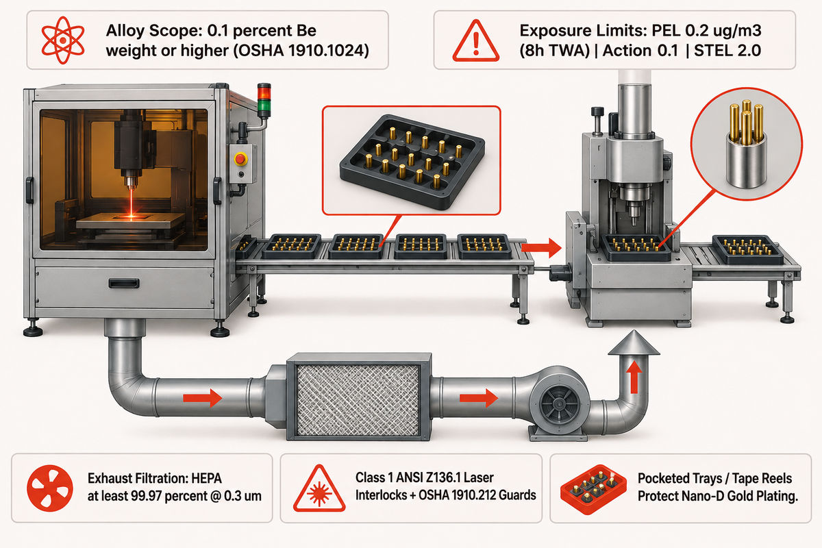
A compliant twist-pin cell protects downstream four-indent crimping hardware while isolating staff from hazardous optical beams and airborne beryllium dust. Bulk handling bends springs and chips plating. Benches without adequate local exhaust breach mandatory OSHA caps and Class 1 safety containment.
Downstream crimping hardware completes MIL-DTL-83513 connector assembly by cleanly inserting a pin blank into a precision metal sleeve. On MIL-DTL-83513 connectors, pure tin finishes are strictly barred: tin content must stay at or below 97% to block tin whiskers. Closed-loop crimp monitoring integrates mechanical closure with pin dimensions to ensure process repeatability. This is detailed in ZEUEE’s article on crimp force monitoring for assembly processes.
Regulatory fume hygiene becomes critical when melting alloys containing 0.1 percent beryllium or higher by weight. OSHA standard 29 CFR 1910.1024 caps the 8-hour TWA Permissible Exposure Limit at 0.2 micrograms per cubic meter and sets the Action Level at 0.1 micrograms per cubic meter. Short-term 15-minute excursions can’t exceed 2.0 micrograms per cubic meter. Local exhaust housings and vacuum cleanups must trap dust through HEPA filters rated at least 99.97 percent efficient at 0.3 micrometers.
Practitioner reports on public welding forums emphasize how quickly open manual beryllium-copper welding causes worker illness when unventilated. Optical enclosure rules require equally tight interlock hardware. OSHA Technical Manual Section III Chapter 6 specifies Class 1 interlocked housings for embedded Class IIIB and Class IV lasers per ANSI Z136.1. Access doors use dual fail-safe series electrical interlocks alongside OSHA 29 CFR 1910.212 pinch-point guarding across automatic shear dies.
When should twist pin blanks discharge in bulk bowls versus carrier trays before sleeve crimping?
Pocketed carrier trays or tape reels protect miniature Nano-D parts and pre-plated blanks that tangle or lose gold finish under vibration. Bulk catch cups work best for bare beryllium copper blanks going directly into a rack or barrel plating bath.
Vibratory bowl tracks polish fine metal tips against neighboring blanks, scuffing nickel-gold coats and denting spring arches. Direct tray indexing protects delicate concentric domes from welding right into multi-indent crimpers.
Sizing Cell Output Using Cycle Time, OEE, Yield Loss, and Spool Changeovers
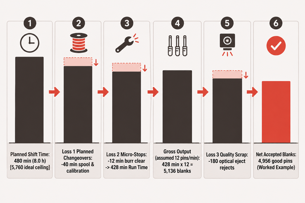
Quoting raw cycle strokes per minute overstates good pins delivered across an eight-hour production shift. Actual plant throughput follows Overall Equipment Effectiveness (OEE) after subtracting planned coil changeovers, micro-stop clearances and Inline CCD rejects. Separating these three loss buckets reveals capacity constraints before purchase orders are issued.
OEE.com defines standard production efficiency as Availability times Performance times Quality. Good Count multiplied by Ideal Cycle Time and divided by Planned Production Time completes the definition. Crucially, Run Time subtracts Stop Time from Planned Production Time, capturing both sudden jam downtime and planned spool changeovers.
Sample 8-Hour Shift Calculation: Walk through a concrete 480-minute shift baseline using the OEE.com production equations. Model an example cycle speed of 12 blanks per minute across continuous indexing. Subtract 40 minutes for planned spool threading and laser focus calibration. Also subtract 12 minutes for shear burr clearing, and subtract 180 optical scrap blanks rejected during inline inspection sorting.
3-Loss Cell Throughput Balance Sheet
| Balance Line Item | Calculation Formula | Illustrative Value | Planning Impact |
|---|---|---|---|
| 1. Planned Shift Time | Scheduled operating window | 480 min (8.0 h) | Shared shift denominator across cell metrics |
| 2. Loss 1: Planned Changeovers & Checks | Spool threading plus calibration stops | −40 min | Subtracted once inside OEE Stop Time |
| 3. Loss 2: Unplanned Micro-Stops | Die burr clears plus gas check stops | −12 min | Yields 428 min net Run Time |
| 4. Gross Cycle Output (at Run Time) | 428 min × 12 pins/min (assumed) | 5,136 blanks | Pre-inspection pin volume produced |
| 5. Loss 3: Quality Scrap Fallout | Optical eject chute reject count | −180 scrap blanks | Eccentric domes, stray wires, length errors |
| 6. Net Accepted Blanks | 5,136 − 180 tray-accepted parts | 4,956 good pins | Compare net pins against 5,760 ideal shift ceiling |
Reducing spool changeover downtime usually adds more shift output than pushing cutter speeds slightly higher. Recovery of dozens of minutes each shift is possible with quick-release wire reels and drop-in shear cartridges. See actual nominal cycle speeds on ZEUEE’s twist pin machine solution page when formulating your factory schedule.
Equipment Integrators vs. Connector OEMs: Engineering RFQ Deliverables and FAT Qualification
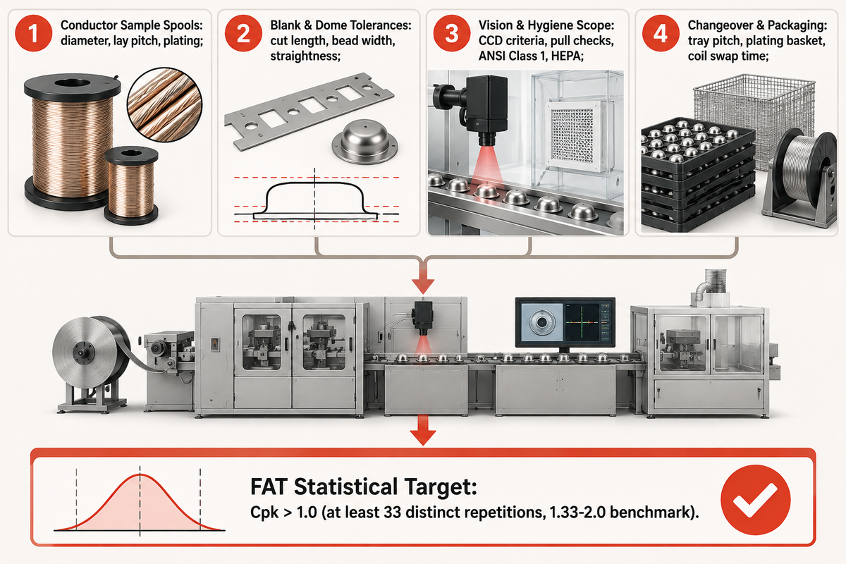
Established connector manufacturers such as Glenair and Omnetics sell QPL MIL-DTL-83513 connector assemblies rather than standalone pin fabrication machinery. Companies that manufacture their own internal contact lines work with specialized automation equipment builders. Sample reels and NIST statistical capability acceptance targets protect schedules from tooling surprises.
That division is clear in public catalogs. Glenair’s Micro-D portfolio supplies DLA-qualified MIL-DTL-83513/01 through /33 connectors. Omnetics builds 9- to 51-pin QPL Micro-D lines using BeCu spring contacts. Neither vendor acts as a general machine tool OEM to sell automatic cutting and welding equipment to outside wire plants.
Dedicated automation builder ZEUEE (founded 2005 in Shenzhen, China) operates a 20,000 m2 Taihe manufacturing base with 0.005 mm machining capability for wire-preparation, laser fusing, and optical inspection machines. Clarification of key engineering requirements in an RFQ prevents tooling delays during sample qualification. Include four technical items in every supplier inquiry:
- Conductor Sample Spools: Provide production reels of helical copper-beryllium or phosphor-bronze wire stating diameter, lay pitch, and surface plating.
- Blank and Dome Tolerances: State acceptable bands of cutting length, limit widths of tip bead for sleeve insertion, and straightness requirements.
- Vision and Hygiene Scope: State CCD camera pass/fail criteria, destructive pull intervals, ANSI Class 1 lasers, and HEPA exhausts.
- Changeover and Packaging Format: Specify carrier tray pitch, plating basket transfer, and acceptable changeover time for each coil size.
Lock quantitative statistical targets directly into Factory Acceptance Testing (FAT) protocols. On NIST Engineering Statistics Handbook thresholds, a capable process exceeds Cpk 1.0. Industry manufacturable benchmarks point to Cpk values of 1.33, 1.5, or 2.0. NIST further shows that stable capability tests require at least 33 distinct repetitions to hold a 95% confidence interval within plus or minus 25% precision. Pair that capability lot with a Gage R&R study separating short-term camera repeatability from operator reproducibility.
Next Step for Equipment Sizing: Explore turnkey subsystem options and nominal throughput classes on the ZEUEE Twist Pin Cutting & Welding Machine commercial solution page. Send your spooled wire specs and target pin tolerances directly to ZEUEE application engineers.
Frequently Asked Questions: Twist Pin Cutting & Welding Machine Engineering & Qualification
Can a single Twist Pin Cutting & Welding Machine process both Micro-D and Nano-D wire gauges?
Yes, if changeover kits cover tighter straightener grooves, micro-shear clearance, and smaller optical inspection windows for thinner Nano-D cables.
Shifting from 0.050-inch-pitch Micro-D blanks down to 0.025-inch-pitch Nano-D conductors changes guide bore clearances, collet clamping force, and laser spot geometry. One base machine can handle both connector families when modular quick-change tooling heads, recalibrated camera magnification optics, and even lower millisecond pulse recipes are specified in the initial RFQ.
Why is dual-end tip welding preferred over single-end welding on helical twist pins?
Dual-end fusing prevents strand splay on both the mating tip nose and the rear tail entering crimp sleeves.
While a smooth rounded hemispherical dome guides blind insertion cleanly within plated female sockets, an unwelded rear cut strand still unravels during vibratory feeders and transfers. Sealing both severed cable faces stabilizes blank cutting length, stops rear birdcaging, and accelerates reliable pin insertion inside downstream four-indent sleeve crimping stations across multi-shift factory lines.
Should copper-alloy twist pin wire be gold-plated before or after laser tip welding?
Most high-reliability operations cut and weld bare or sub-plated wire first, then barrel-plate nickel and gold over the finished blank.
Fusing unplated beryllium-copper wire cable prior to plating prevents surface gold layers from boiling off inside solidifying weld domes and stops brittle intermetallic porosity. Running barrel electroplating over completed blanks afterward seals the entire helical spring body, active arched waist, and welded dome uniformly under protective nickel barriers and gold.
How do engineers decide between mechanical shearing and laser severing prior to tip fusion?
Mechanical carbide shearing under opposing collets wins most production lines due to cycle speed, zero thermal pre-damage, and clean flat ends.
Cutting helix-wound seven-strand copper wire with matched shear dies creates sharp planar ends that are ready for immediate welding. Compared to laser severing, mechanical shear dies leave burr-free cut faces, whereas thermal cutting leaves brittle recast slag behind. Laser cutting wastes valuable optical pulse energy trying to sever dense, highly reflective copper wire bundles. Optical cutting pushes unwanted heat back toward the tempered beryllium-copper spring bulge and adds hazardous metallic dust to the closed work chamber. Laser cutting is used only for extremely fragile custom ribbons and situations where steel blades distort bundle geometry or leave a smear burr. Rigid dual guide bushings with tool-free tungsten-carbide inserts provide the repeatability required for long, automatic production runs.
What inline CCD camera checks should be included to prevent oversized weld balls from jamming crimp sleeves?
Require telecentric measurement of maximum weld ball diameter, dome coaxial concentricity relative to wire centerline, and stray whisker projection detection.
Even slight weld ball asymmetry pushes the domed pin nose past its mating sleeve chamfer during loading, bending four-indent crimp contacts. High-contrast sub-pixel edge detection, telecentric backlighting, and non-contact scanning allow vision camera systems to check each pin blank at line indexing pace. The frontal oblique lighting provides additional light to reveal a dark brown oxidation tint, caused by argon shielding gas flow interruptions. Quality teams run formal NIST repeatability studies to qualify camera magnification before signing off factory acceptance rejection thresholds.
What ventilation and laser enclosure standards apply when welding beryllium-copper pin wire?
Cells processing alloys at or above 0.1 percent beryllium must integrate Class 1 ANSI Z136.1 optical housings with OSHA 1910.1024 HEPA fume capture.
Copper-beryllium alloys heated by laser pulses generate toxic metal oxide particles and stray reflected laser light that must remain contained within the work enclosure. A negative-pressure local exhaust system with a HEPA filter rated 99.97 percent efficient at 0.3 micrometers protects workers below OSHA’s 0.2 microgram per cubic meter 8-hour TWA PEL. Each removable housing panel must use dual fail-safe series electrical interlocks per OSHA Technical Manual guidance to extinguish embedded Class 4 lasers. Physical perimeter guards around automatic wire drive pinch points and high speed carbide shear must also adhere to the OSHA 29 CFR 1910.212 safety requirements.
What sample wire lots and drawings do machine builders need before quoting a custom twist-pin cell?
Send full part prints, alloy temper certificates, target cutting length tolerances, spooled wire test coils, and required FAT Cpk statistical targets.
No dependable integrator can guarantee wire straightness or solid tip fusion from nominal catalog tables. Providing actual wound test spools gives engineers the opportunity to measure cast memory and surface film response to 450 nm blue or IR laser pulses and shear burr formation before cutting custom dies. Clear RFQ packages also define discharge hardware format (carrier trays vs. open plating baskets) and determine daily shift allowances. Also, specify FAT validation runs of at least 33 consecutive pins to verify Cpk in accordance with NIST guidelines, to assess stability of your automatic cutting machine and welding cell.
Published by ZEUEE (Shenzhen Zeyu Intelligent Industrial Science Technology Co., Ltd), Shenzhen, China. This engineering process guide synthesizes public military, safety, metallurgical, and quality standards with a worked OEE arithmetic example; buyer drawings and FAT protocols govern machine setup.
References & Sources
- Defense Logistics Agency ASSIST: MIL-DTL-83513 Revision H Amendment 2 (Sept 13, 2023)
- OSHA 29 CFR 1910.1024: Beryllium Permissible Exposure & HEPA Filtration Standard
- OSHA Technical Manual Section III Chapter 6: Laser Hazards & Class 1 Interlocks
- NIST Engineering Statistics Handbook: Capability Index Cpk & Metrology Glossary
- NASA Johnson Space Center (MSC-TOPS-106): Radiography & Crack POD Boundaries
- Choi et al. (NIH PMC, 2026): Copper Laser Beam vs. Resistance Welding Review
- Copper Development Association: Alloy C17200 Beryllium Copper Properties
- Materion: Age Hardening & Thermal Windows for Wrought Copper-Beryllium
- Iqbal & Sadeghian (ScienceDirect, 2023): Blue vs. Infrared Laser Copper Absorption
- Kitagawa et al. (ScienceDirect, 2026): Laser Beam Oscillation Amplitude & Stability Limits
- ConnectorSupplier: MIL-DTL-83513 Twist-Pin Mechanics & Tin Exclusion Rules
- ConnectorSupplier: High-Reliability Micro-D, Nano-D, and Alloy 290 C17200 Materials
- Military Embedded (2026): Micro-D vs. Nano-D & D-Sub Engineering Guide
- UTMEL (citing NASA NTRS 20220017466): Wire Preparation Defects & Pull-Force Checks
- Phoenix Laser: Empirical Laser vs. TIG HAZ Width on Beryllium Copper
- Han’s Laser US (2026): Red-Blue Composite Laser Connector Wire Joining
- OEE.com: Overall Equipment Effectiveness & Planned Stop Time Formula
- USPTO US3258736A (IBM, 1966): Helical Resilient Wire Male Connector Contact
- USPTO US7775841B2 (QA Technology, 2010): Mandrel & Laser-Welded Contact Socket Method
- Glenair: QPL MIL-DTL-83513 Micro-D Connectors & Hardware Catalog
- Omnetics Connector Corp.: Standard & MIL-DTL-83513 Micro-D Product Line
WHY WE WRITE THIS
About ZEUEE Engineering Insights
ZEUEE shares technical guides based on real automation project experience. Since 2005, we have designed and manufactured non-standard automation equipment for connector assembly, wire harness production, robotic lines, vision inspection, and smart factory upgrades.
Founded in 2005
20,000 m² production base
120+ specialists
150+ R&D patents
ISO9001:2015 certified