Get in touch with Zeyu lntelligent Industrial Company

Color Ring Coating Machine Guide: Band Transfer, UV Curing & CCD Inspection

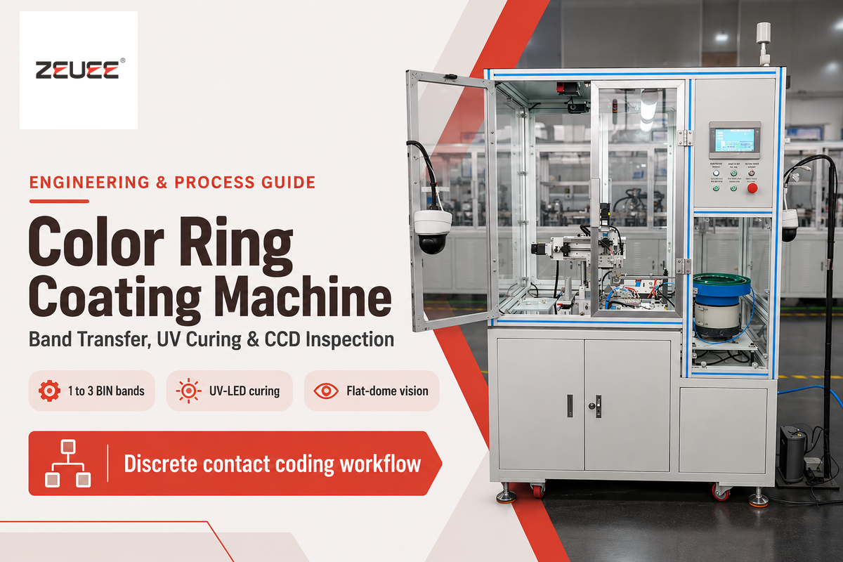
A color ring coating machine applies 1 to 3 concentric identification bands around discrete cylindrical contacts. Published pin-coding benchmarks sit near 60 cycles per minute (roughly one contact per second), while larger fuse-tube coaters reach up to 100 pieces per minute. Complete three-digit SAE AS39029 Basic Identification Number (BIN) codes require three bands. Knowing rotary transfer mechanics, UV-LED curing limits, and camera grading stops buyers from quoting bulk spray booths or vacuum chambers by mistake.
Updated November 2026 · By Cherry
Engineering Summary
- Target parts include discrete cylindrical pin and socket contacts (SAE AS39029 sizes #22D through #12), terminals, and small shafts.
- Single-pass cells deposit 1 to 3 concentric bands, with three bands encoding a full three-digit BIN sequence.
- Cure sources use narrowband UV-LED emitters (365, 385, 395, or 405 nm) matched to ink photoinitiators, or controlled thermal baking.
- Quality gates pair diffuse flat-dome optics with inline CCD color grading and sensor-confirmed reject diversion.
A discrete color ring coating machine deposits 1 to 3 bands on cylindrical connector contacts in one indexed cell. It also uses UV-LED curing and inline CCD inspection.
What Is a Color Ring Coating Machine and How Does Rotary Band Transfer Work?
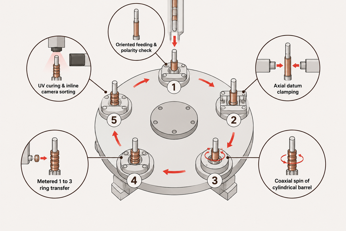
Color ring coaters index discrete cylindrical contacts around a rotary turntable, spin the part against a metered applicator, and immediately cure the ink. A camera is used to sort rejects. Unlike bulk paint booths, these cells apply stripes only to the designated wire barrel while maintaining the mating surfaces bare.
How does a color ring coating machine work on cylindrical contacts?
An automated contact coater performs five functions: oriented feeding and polarity check; axial datum clamping; coaxial spin; metered ring transfer; and UV curing with inline camera sorting. First, the feeder singulates the bulk supply (pins or sockets) and checks axial polarity so the wire barrel faces the applicator. Second, a positive stop is used to locate the contact along its axis so band position is repeatable.
Third, a coaxial chuck or collet carrier rotates the cylinder at a controlled speed. Fourth, transfer wheels, metered dispensing needles, or doctor-bladed rollers contact the spinning barrel and apply 1, 2, or 3 rings in one pass. Fifth, the turntable indexes the contact, and UV curing is used along with camera grading to check quality. Off-spec lots are diverted.
Published third-party patents show how engineers form narrow bands on miniature barrels. For example, published patent CN118744073A (Shanghai Workpower Telecom Co., Ltd.) discloses an embodiment with 0.5 mm and 1.0 mm ring widths at a 1.0 mm pitch. That design uses 27G (0.42 mm OD) and 30G (0.31 mm OD) needles, a pneumatic chuck, and a Shore A50 silicone scraper.
A separate external filing, published patent CN122558722A (Kunshan Aisyitian Automation), describes an electric rotary table paired with a vibration feeder and spring-collet follower carriers. It uses an axial pushing datum, rubber drive wheels and a laser unload sensor. Neither of the two publications discloses ZEUEE intellectual property. Earlier snap-on clips in expired U.S. Patent US6311229B1 (Elsag International BV) fit block I/O housings, not tight circular connector cavities that rely on cured liquid rings.
Discrete contact coaters run on a continuous single-part index rather than batch trays. ZEUEE’s engineering reference places discrete contact cells near one contact per second, applying up to three bands per pass to render a full three-digit BIN code with vision grading. That continuous coating rhythm differs sharply from reel-fed strand lines such as Rosendahl Nextrom’s MCM system, which marks 80+ optical fiber IDs at 1,600 m/min.
Separating Contact Ring Coaters from Bulk Industrial Coating Systems
Confusing discrete contact coaters with bulk surface-finishing lines can lead buyers to obtain irrelevant machine quotes. A powder coating booth sprays dry thermoset polymer across metal panels, while a vacuum coating machine uniformly deposits metallic thin films on racked trays inside a vacuum chamber. In contrast, the cited contact-coating patent (CN118744073A) focuses on selective narrow liquid stripes on individual wire barrels.
A similar situation exists in used machinery catalogs for the pharmaceutical and confectionery industries. A coating kettle rotates a tumbling pan to roll tablets and build a uniform film coating on all sides. In pharmaceutical catalogs, a sugar coating partially perforated drum tumbles tablets in heated air. A partially perforated drum pneumatically operated for batch discharge handles bulk cores rather than delicate brass or beryllium-copper pins.
| Equipment Category | Primary Process Mechanism | Coverage Geometry | Fit for Contact BIN Coding |
|---|---|---|---|
| Discrete Color Ring Coating Machine | Indexed spin + metered wheel or needle transfer + UV cure | 1–3 selective 360° bands on wire barrel | Keeps gold mating zone bare; supports CCD color grading |
| Continuous Fiber Ring Marker | Non-contact wet-on-wet jetting on moving strand | Periodic rings along 1,600 m/min fiber | Designed for continuous flexible strands, not rigid singulated pins |
| Batch PVD / Magnetron Chamber | Multi-arc ion and magnetron sputtering in vacuum | Full-surface metallic thin film on racks | Built for full-surface plating rather than multi-color BIN bands |
| Bulk Pan, Drum, or Powder Booth | Tumbling spray drum or electrostatic powder gun | Unselective full-part coating layer | Risk of pin deformation and unwanted coverage on mating surfaces |
Selection boundary: Use a continuous strand marker for flexible wire or optical fiber off a reel. Rigid machined contacts typically use fixture-based rotary indexing when automated multi-color banding is selected over manual or batch methods.
Contact Geometry, Band Width Tolerances, and Ink Curing Specs
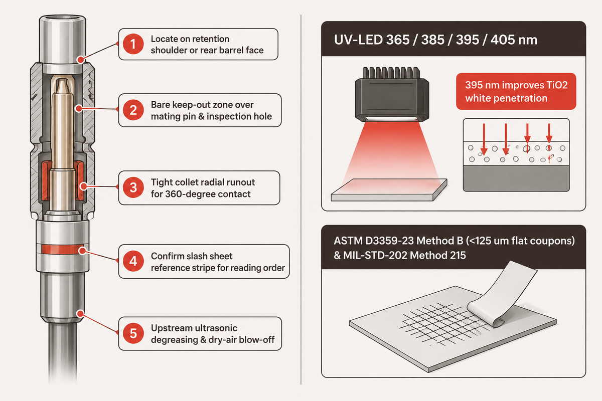
After rotary band transfer deposits wet ink onto a wire barrel, contact geometry and curing physics determine whether those bands survive crimping and cleaning. Engineers tie band zones to SAE AS39029 slash sheets, keep ink off gold mating surfaces, and match UV-LED wavelength and dose to the ink chemistry.
SAE AS39029 Contact Families and BIN Band Layout
Aerospace and defense connectors built to MIL-DTL-38999 or MIL-DTL-26482 use removable contacts governed by SAE AS39029 (formerly MIL-C-39029). According to ISO/IEC 17025 lab Lectromec’s AS39029 review, qualified contacts, including those used in MIL-DTL-38999 connectors, must withstand at least 500 mating cycles, limit axial displacement to no more than 0.3 mm, and pass shock tests checking for electrical discontinuities lasting longer than 1 microsecond. Lectromec summarizes the mechanical retention baseline directly:
“Size 22 contacts in MIL-DTL-38999 connectors must withstand at least 10 lbf (44 N) axial force without dislodging, and larger contacts (Size 16, 12, etc.) have even higher minimum retention requirements (up to 25 lbf or ~111 N for the largest size).”
Gold plating makes ink adhesion harder than marking bare steel or plastic. Connector Supplier’s M39029 guide notes that the spec historically required 0.000050 in (50 microinches) of gold over the entire outer body, though selective gold plating is now permitted. Smooth gold has low surface energy and offers minimal grip for wet ink. Residual machining oil causes pinholes or flaking after cure. For upstream mechanical tolerances before banding, review our guide to pin and socket contact assembly workflows.
On SAE AS39029 contacts, three color bands encode the three-digit Basic Identification Number (BIN), read from the wire barrel toward the mating tip. Exact contact barrel diameters and band-width tolerances come from each part’s specific M39029 slash sheet rather than one universal table. Patent CN118744073A illustrates sub-millimeter and millimeter-scale ring widths for crimping contacts, whereas the Ø4.4–5.9 mm range cited on Yulishih’s TIU-03 applies to larger fuse tubes rather than miniature pins. The reference matrix below compiles eleven published MILNEC and Aiconics M39029 contact models across sizes #22D through #12.
| Contact Model | Contact Type & Size Class | Wire Gauge (AWG) | Published BIN Color Sequence | Primary Coating & Feeding Focus |
|---|---|---|---|---|
| M39029/58-360 | Pin · Size #22D | 22–28 AWG | Orange, Blue, Black | Low-drop feeding to avoid bending thin pins; tight axial datum |
| M39029/56-348 | Socket · Size #22D | 22–28 AWG | Orange, Yellow, Gray | Protect slotted socket hood; verify contrast on gray/yellow bands |
| M39029/58-363 | Pin · Size #20 | 20–24 AWG | Orange, Blue, Orange | Strict keep-out clearance near shoulder and inspection hole |
| M39029/56-351 | Socket · Size #20 | 20–24 AWG | Orange, Green, Brown | Diffuse lighting to separate brown and orange hues on gold |
| M39029/1-100 | Pin · Size 16 / Barrel 22 | 22 AWG | Brown, Black, Black | Stepped barrel geometry requires matched collet diameter |
| M39029/1-101 | Pin · Size 16 / Barrel 20 | 20 AWG | Brown, Black, Brown | Verify axial orientation before ink transfer on reduced barrel |
| M39029/58-364 | Pin · Size #16 | 16–20 AWG | Orange, Blue, Yellow | Verify UV dose on opaque yellow pigment across full circumference |
| M39029/56-352 | Socket · Size #16 | 16–20 AWG | Orange, Green, Red | Calibrate camera hue gap between red and orange bands |
| M39029/58-365 | Pin · Size #12 | 12–14 AWG | Orange, Blue, Green | Heavier contact mass needs cushioned feed tracks to limit scuffing |
| M39029/56-353 | Socket · Size #12 | 12–14 AWG | Orange, Green, Orange | Confirm full circumferential UV exposure on larger barrel diameter |
| M39029/31-234 | Pin · Size #12 | 12–14 AWG | Red, Orange, Yellow | High-chroma three-color check under diffuse flat-dome illumination |
BIN-Band Tolerance Stackup Checklist
Check five dimensional and surface-preparation inputs listed in the BIN-Band Tolerance Stackup Checklist before releasing a contact drawing to an equipment builder. Misalignment of these inputs can lead to dimensional drift and ink spread, which could result in scrap.
- Locate the contact on the retention shoulder or the rear barrel face, rather than on the delicate mating tip.
- Define a bare keep-out zone over the active mating pin, socket hood, and crimp inspection hole.
- Hold collet radial runout tight to ensure the transfer wheel or needle makes consistent contact 360 degrees around.
- Confirm on the applicable M39029 slash sheet if the first band uses a wider reference stripe for reading order.
- Verify upstream ultrasonic degreasing and dry-air blow-off before coating production so machining oils do not impair wetting.
UV-LED Curing Physics and Ink Formulation Sensitivity
Commercial UV-LED arrays emit narrowband UVA peaks at 365, 385, 395, or 405 nm with zero infrared heat, per GEW’s UV curing guide. UV inks combine 50–80% oligomers, up to 50% monomers, and 0.5–15% photoinitiators that cross-link rather than drying by solvent evaporation. Pigment opacity heavily affects wavelength selection. UVNDT notes that white ink contains Titanium Dioxide (TiO2), which blocks UV light below 380 nm. Under white pigment, a 365 nm lamp risks leaving the bottom coating layer under-cured. Moving to 395 nm improves penetration when matched to photoinitiator absorption, film thickness, and delivered UV dose.
Cure windows depend on ink formulation rather than lamp wattage alone. Researchers at the National Institute of Standards and Technology (NIST) (Bennett, 2017; updated May 7, 2026) measured five commercial additive-manufacturing photopolymer resins at 365 nm and 405 nm. They recorded up to 7X variation in critical curing energy (Ec) and 10X variation in penetration depth (Dp). That study evaluated additive-manufacturing resins rather than contact striping inks, yet it illustrates formulation sensitivity. Because a UV radiometer measures lamp irradiance and dose rather than ink adhesion directly, engineers pair radiometer output logs with actual cure and solvent tests on coated sample contacts. The same NIST study also found caliper checks inaccurate on soft elastomers, favoring optical or profilometer gauges during qualification.
Worked Circumferential Rotation and UV Exposure Calculation
Suppose an engineer models a contact with an assumed 1.60 mm wire-barrel outer diameter spinning at 150 rpm past a single-line UV beam for 0.30 s. Circumferential surface speed equals pi × 1.60 mm × (150 ÷ 60) = 12.57 mm/s. One complete revolution equals pi × 1.60 mm = 5.03 mm. During 0.30 s, the barrel turns 12.57 × 0.30 = 3.77 mm, or 0.75 of a full revolution (270 degrees). Because the barrel hasn’t completed one full turn past a point-line beam, part of the circumference receives no direct beam pass (exact unexposed arc depends on the emitter’s optical coverage angle). Extending dwell to 0.40 s completes one full revolution, while complete through-cure still requires matching ink photoinitiator chemistry, film thickness, and delivered energy dose.
What ink adhesion and solvent tests verify cured contact color bands?
ASTM D3359-23 tape-adhesion testing and MIL-STD-202 Test Method 215 solvent-permanence testing are two core methods used alongside customer drawing criteria to verify coating requirements. ASTM D3359-23 (Active, March 2023) scores metallic-substrate tape adhesion from 0 to 5 using a rapid 180-degree peel. Method B applies to films thinner than 125 μm (5 mils), while Method A applies above 125 μm; Method B can also extend past 125 μm when wider cut spacing and explicit buyer-seller agreement apply. Because ASTM D3359’s 0–5 ranking measures neither absolute peel force nor narrow curved contact rings directly, quality labs test flat matching-plating witness coupons cured inside the same machine. On actual contacts, labs run MIL-STD-202 Test Method 215 solvent-permanence tests. DESolutions and eComp testing guides confirm that Method 215 exposes marked parts to solvents such as mineral spirits, acetone, NMP, or Dynasolve to check marking legibility and discoloration resistance.
Cure boundary: If opaque white or yellow bands fail solvent permanence under 365 nm UV, check ink photoinitiator compatibility and the delivered UV dose first. Check surface oxygen inhibition and substrate degreasing before altering the lamp wavelength or film thickness.
Rotary Color Ring Coating vs. Hand Painting, Pad Printing, Laser, and PVD Methods
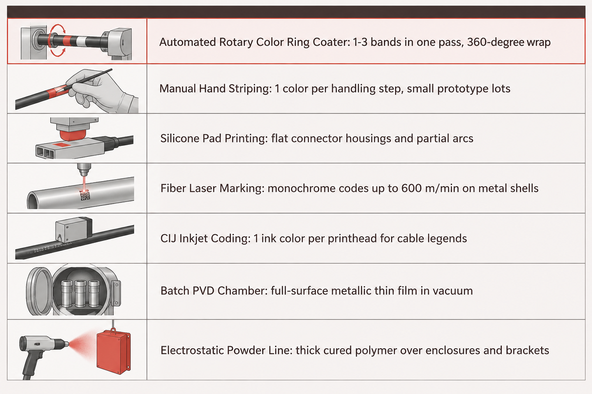
Automated rotary color ring coating fits discrete cylindrical contacts needing three crisp 360-degree BIN bands when volume, changeover cadence, and inspection justify a dedicated cell. Manual striping and currently accepted methods are viable for lower volume applications. Laser, inkjet, and PVD systems are used for different marking applications.
When should engineers choose automated rotary coating instead of laser or inkjet marking?
Choose an automated rotary color ring coater when drawings require multi-color 360-degree bands and production volume, repeatability, and inspection needs justify a dedicated cell. Fiber lasers excel at fast monochrome text and 2D codes. Videojet documents 50W fiber lasers and a 100W fiber laser operating up to 600 m/min on metal parts, alongside continuous inkjet (CIJ) units loaded with MIL-SPEC alphanumeric inks. Those systems, however, target alphanumeric codes, barcodes, and continuous legends rather than multi-color resistor bands on thin gold-plated barrels.
Similarly, silicone pad printing targets flat housings or partial arcs unless multi-hit rotary fixtures are added. Standard CIJ printheads also require specialized rotary synchronization and narrow droplet registration to band tiny discrete pins. Dedicated rotary contact coaters address these integration challenges out of the box. External published specs list Adapt Automation’s Model 1174 at an estimated 60 cycles per minute for 1–3 contact stripes. Yulishih’s TIU-03 UV ring coater specifies up to 100 pcs/min (including curing) on larger Ø4.4–5.9 mm fuse tubes.
Broad searches also bring in a PVD coating machine or a coating machine for jewelry manufacturers intended for full-surface decorative coating. For example, a magnetron sputtering coating chamber with dimensions of φ1300 × H1300 mm coats racked hardware uniformly in vacuum batches rather than striping individual electrical pins. Additionally, a professional powder coating booth or a complete industrial powder coating line employs an electrostatic powder spray gun designed for cabinets and brackets. Consumer hardware multifunctional coating lines require custom masking and fixturing steps that add complexity compared with dedicated single-pin rotary coaters.
| Method | 360° Band Integrity | Colors per Pass | Substrate Impact | Published Reference Speed | Best-Fit Application |
|---|---|---|---|---|---|
| Automated Rotary Color Ring Coater | Continuous 360° wrap via coaxial spin | 1–3 bands in one pass | Non-ablative liquid/UV ink on wire barrel | ~60 cycles/min est. (Adapt 1174 pins); up to 100 pcs/min (Yulishih TIU-03 fuses) | Production M39029 aerospace/defense contacts and terminals |
| Manual Hand Striping | Operator-dependent overlap and edges | 1 color per handling step | Non-ablative; high tray-smear risk | Manual bench rate | Small prototype lots and engineering samples |
| Silicone Pad Printing | Suited to flat or partial-arc faces unless rotated | 1–2 colors via indexed hits | Non-ablative; needs rotary tooling for full wrap | Batch fixture indexing | Flat connector housings and single-side legends |
| Fiber Laser Marking | Monochrome contrast; rotary axis required | 0 standardized pigment colors | Surface-oxide marking; verify thin-gold integrity | Up to 600 m/min on metal (Videojet 50W/100W) | Alphanumeric lot codes and 2D codes on shells |
| CIJ Inkjet Coding | Requires synchronized rotation for full rings | 1 ink color per printhead | Non-contact; MIL-SPEC text inks available | High-speed continuous cable lines | Cable jacket legends and flat metal brackets |
| Batch PVD Chamber | Unselective full-part film unless masked | 1 uniform chamber finish per run | Deposits metallic film across exposed surfaces | Batch vacuum cycle (pump-down <=20 min in cited spec) | Decorative jewelry and full-surface hardware plating |
| Electrostatic Powder Line | Unselective spray coverage unless masked | 1 powder finish per booth pass | Thick cured polymer coat over exposed metal | Conveyorized booth & oven batching | Enclosures, brackets, and structural panels |
Decision rule: Maintain laser or CIJ units for connector shells and cable jackets, while matching manual striping or automated rotary cells to batch volume, changeover cadence, and qualified processes.
Part Feeding, Axial Orientation, and Quick Color Changeover Control
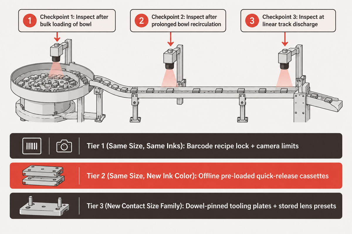
Actual shift yield is governed by part feeding and color changeover more than turntable cycle speed. Fragile gold-plated pins bend or scuff when vibratory bowl amplitude climbs too high. High-mix contact shops also lose uptime unless ink cassettes, rollers, and tooling swap under repeatable controls.
How do you prevent contact pin bending during automated bowl feeding?
Select the appropriate feeding mechanism for contact stiffness, rather than forcing every pin through a bare steel bowl. Bulk bowls, such as the 18-inch stainless bowl on Adapt Automation’s Model 1174 or the 5,000-piece hopper on Yulishih’s TIU-03, handle sturdy terminals and fuse tubes cleanly. Thin Size #22D pins and slotted sockets can tangle and become distorted under the weight of recirculating parts. Use low-drop magazine or tube loaders to maintain yield for fragile geometries.
While protective bowl linings help cushion parts, they can’t overcome deficiencies in mechanical tooling. Lancing UK Bowlfeeders stresses that elastomer linings can improve friction or reduce bounce, but cannot replace correct tooling, orientation logic, and part-quality control. Monitor contacts at three separate points during the commissioning process: after the bulk loading of the bowl, after prolonged bowl recirculation, and at the discharge of the linear track. Looking at all three allows the determination of whether gold scuffs are from hopper weight, rail burrs or escapement pinch.
RNA Automation’s August 2026 bowl-feeder analysis highlights a frequent floor trap. Suppose a vibratory feeder delivers a steady 200 parts per minute into a coating cell. Supervisors see stable feed counts and assume orientation is equally steady. Meanwhile, subtle rail wear and excess vibration amplitude let pins hop past orientation wipers and enter the chuck backward. As RNA Automation warns, more vibration isn’t always better. Within an hour, the coating machine integrates flipped contacts into the transfer station, striping the mating tip instead of the barrel and filling the reject chute.
Install an optical or laser polarity sensor in front of the loading escapement to divert reversed contacts dry. Match feeder tooling nests carefully when grouping mixed connector families; review our guide on connector contact types and geometry selection during tooling layout.
Last-Good-to-First-Good Changeover Clock
Recipe recalls cited as two minutes may count touchscreen clicks alone. High-mix shops should use the Last-Good-to-First-Good Changeover Clock to measure true downtime. Measure every minute from the final accepted pin of Lot A to the first vision-verified pin of Lot B across three operational tiers:
| Changeover Tier | Physical & Software Actions | Main Downtime Driver | Control to Compress Clock |
|---|---|---|---|
| Tier 1: Same Size, Same Inks | Load HMI recipe; reassign active heads and BIN check | First-article color order sign-off | Barcode recipe lock + automatic control of camera limits |
| Tier 2: Same Size, New Ink Color | Swap ink cassette and wheel or flush needle manifold | Solvent purge and shade stabilization | Offline pre-loaded quick-release color cassettes |
| Tier 3: New Contact Size Family | Swap track, collet nests, axial stop, and camera focus | Mechanical alignment and runout check | Dowel-pinned tooling plates + stored lens presets |
Changeover rule: If your line changes BIN ink colors more than twice per shift, specify removable pre-inked applicator cassettes so technicians avoid wet solvent flushes inside the frame.
In-Line Machine Vision Verification and Defect Troubleshooting
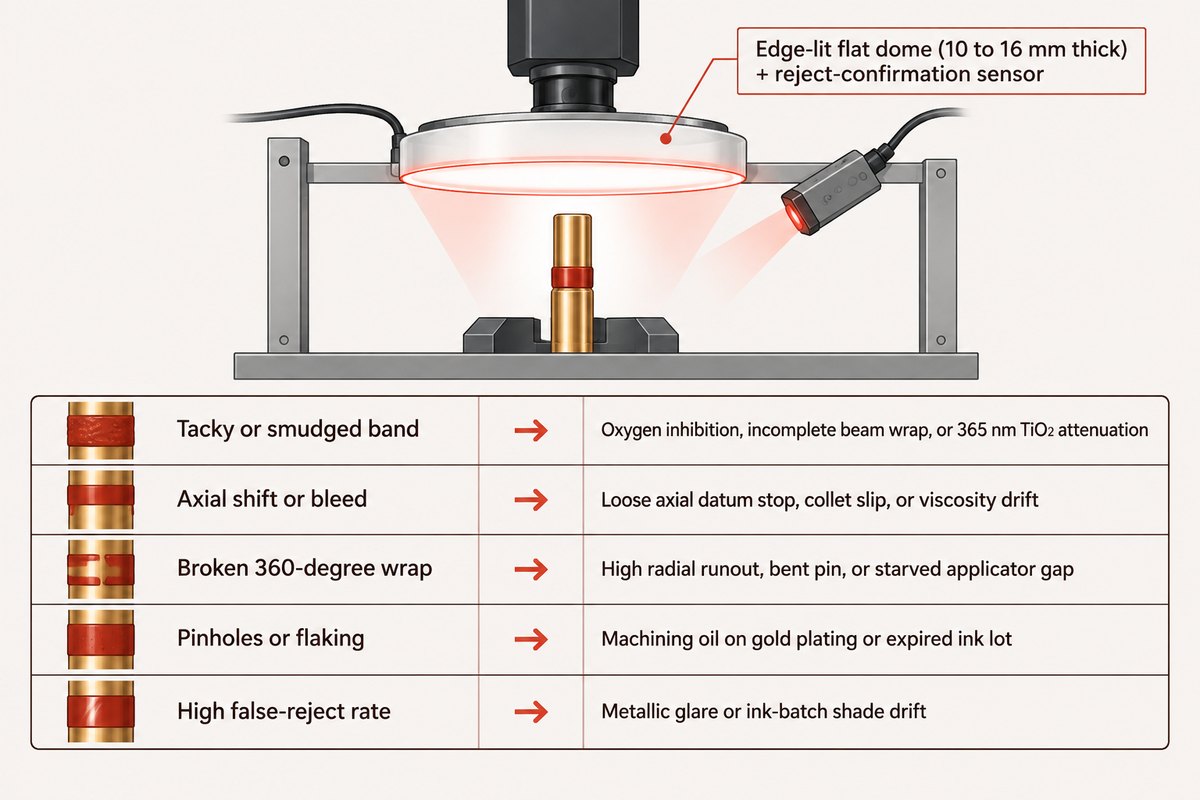
In-line machine vision can inspect visible coating features in an open-loop coating process. Because curved gold pins act like mirrors, accurate grading requires calibrated color windows, diffuse flat-dome illumination, and deterministic reject sorting linked to physical root causes.
Taming Specular Glare on Reflective Gold-Plated Cylinders
Standard ring lights struggle on shiny cylindrical contacts. Point-source LEDs cast a bright white glare line along the crest of a gold pin while leaving the sides dark. That distortion shifts measured hue and triggers false rejects between brown, red, and orange bands. In Vision Systems Design’s cylindrical-lighting study (Joe Gugliotti and Marc Landman, September 2020), the authors examine an edge-lit flat dome. Measuring 10 to 16 mm thick with a clear viewing window, it wraps shiny metallic cylinders in even diffuse light. Unlike traditional hemispherical domes, a flat dome eliminates both glare hot spots and the dark camera-hole reflection across the cylinder.
Combine diffuse optics with multi-angle imaging or rotation under the lens so the control system checks full 360-degree wrap continuity. Four traits should be graded for each contact: BIN color sequence, band width, axial offset from the shoulder, and keep-out cleanliness. For each reject blow-off or diverter, a reject-confirmation sensor should be used so that a missed ejection stops the index table. For other best practices for camera setup, check out our connector inspection automation and vision verification guide.
Why does a color ring coating machine produce smudged or misaligned bands?
Smudged or misaligned bands commonly trace to excess ink transfer, axial slip inside the chuck, worn scrapers or needles, incomplete UV cure, ink-viscosity drift, surface contamination, or unload-handling contact. UVNDT’s curing guide identifies oxygen inhibition as a frequent surface issue under narrowband 395 nm UV-LED lamps. The band looks dry yet feels tacky because atmospheric oxygen quenches free radicals at the top of the coating layer, causing smearing in the unload chute.
Technicians should never mask mechanical drift with tape or temporary shims, an industrial maintenance failure mode that hides worn fixtures until entire lots scrap. Isolate recurring defects cleanly with the Coating-to-Cure Defect Isolation Protocol below.
| Observed Defect | Physical Root Cause | Immediate Corrective Action | Preventive Trigger |
|---|---|---|---|
| Tacky or smudged band in tray | UV-LED oxygen inhibition, incomplete circumferential beam coverage, or 365 nm attenuation by TiO2 | Verify ink-compatible wavelength (e.g., 395 nm for TiO2 white), full 360° beam coverage (single-turn dwell or dual-sided array), and radiometer dose | Per-shift quartz window clean and radiometer irradiance log |
| Axial shift or mating-zone bleed | Loose axial datum stop, collet slip, viscosity drift, or over-filled ink gap | Re-seat shoulder datum; verify chuck clamp pressure; cut transfer film depth | Audit datum wear and clamp force at every Tier 3 tooling swap |
| Broken 360° ring wrap | High radial runout, bent pin in chuck, or starved applicator gap | Check bowl amplitude and bent-pin gate; re-zero head gap | Inspect feed rails and swap worn silicone scrapers on schedule |
| Pinholes or flaking after solvent test | Machining oil on gold plating or expired ink lot | Quarantine lot; check upstream degreasing; load fresh ink | Track ink shelf life and run MIL-STD-202 Method 215 check at lot startup |
| High false-reject rate | Metallic glare or ink-batch shade drift outside camera tolerance | Clean flat-dome diffuser; verify camera window against master pin | Recalibrate white balance on every new ink batch |
Clean UV quartz lenses and log radiometer irradiance on every opaque white or opaque yellow ink change before adjusting PLC index timing.
Aerospace, Automotive, and Industrial Compliance Boundaries
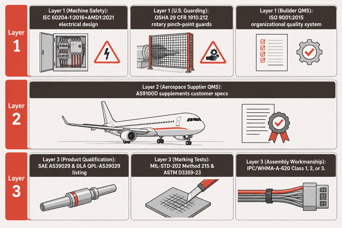
Aerospace and automotive audits stall when buyers equate machine safety marks with qualified electrical contacts. Regulatory responsibility divides into three layers: Layer 1 covers machine safety and OEM governance (including ISO 9001:2015), Layer 2 covers aerospace supplier QMS (AS9100D), and Layer 3 covers contact and assembly qualification.
Three-Layer Separation: Machine Safety, Organizational QMS, and Contact Qualification
Auditors strictly separate the three main areas of responsibility during a quality management audit: machine safety, quality management and component qualification. These three areas must be strictly separated in all procurement documents.
- Layer 1 covers machine hardware safety and builder governance. Electrical design of the coating equipment falls under IEC 60204-1:2016+AMD1:2021 (sixth edition, canceling the 2005 fifth edition) starting at power supply entry. In workplaces under U.S. federal jurisdiction, OSHA 29 CFR 1910.212 mandates barrier or electronic guarding at rotary and pinch-point hazards, explicitly restricting hand-feeding tools to a supplemental role. Equipment builders like ZEUEE document applicable CE conformity declarations, CQC product approvals where required, and ISO 9001:2015 organizational quality management separately, none of which certify contact-level performance.
- Layer 2 covers organizational aerospace quality management (AS9100D). AS9100D incorporates ISO 9001:2015 and adds aviation, space, and defense organizational quality rules. It certifies the supplier’s quality management system; it supplements rather than replaces customer drawings and never qualifies an individual contact or coating machine.
- Layer 3 covers contact and assembly product qualification. Military and aerospace SAE AS39029 contacts require active product listing under QPL-AS39029 in the Defense Logistics Agency’s Qualified Products Database (QPD). Buying a coating cell never places a contact onto QPL-AS39029. When required by the contact specification, contact manufacturers verify solvent permanence under MIL-STD-202 Method 215. Downstream cable assembly builders verify termination and assembly workmanship under IPC/WHMA-A-620 when specified by contract.
According to OSHA 29 CFR 1910.212(a)(3)(iii), special hand tools used to place or remove small cylindrical contacts at a point of operation may only be used to supplement required guarding, and may never be substituted for mechanical or electronic guards in the U.S.
Workmanship classes also follow service definitions rather than blanket industry labels. Spartronics’ April 2026 review confirms that IPC/WHMA-A-620 complements ISO 9001 rather than replacing it. Class 1 covers general electronic products, Class 2 covers dedicated-service electronic products, and Class 3 covers high-performance or harsh-environment products. The Space and Military Avionics Addendum applies when specified by contract. Cloom Tech’s class comparison adds that most automotive electrical assemblies carry a Class 2 rating, reserving Class 3 for safety-critical circuits. For downstream circular shell rules, see our MIL-DTL-38999 circular connector assembly requirements guide.
| Standard / Regulation | Compliance Layer | Primary Owner | Scope Boundary |
|---|---|---|---|
| IEC 60204-1:2016+AMD1:2021 | Layer 1: Machine Safety | Equipment OEM | Machine electrical safety from supply entry; not contact BIN tests |
| OSHA 29 CFR 1910.212 | Layer 1: Machine Safety (U.S.) | OEM & Plant EHS | Guarding of rotary pinch points in U.S. workplaces; hand tools supplement guards |
| ISO 9001:2015 | Layer 1: Builder QMS | Equipment OEM | Organizational quality management system; not a product performance mark |
| AS9100D | Layer 2: Aerospace Organizational QMS | Aerospace Supplier | Aviation/space/defense QMS; supplements customer specs and does not qualify parts |
| SAE AS39029 & DLA QPL-AS39029 | Layer 3: Product Qualification | Contact Manufacturer | 500-cycle durability, retention, geometry, and active QPD listing |
| MIL-STD-202 Method 215 & ASTM D3359-23 | Layer 3: Marking Verification | Contact / Assembly QA | Solvent legibility on contacts + 0–5 tape score on flat witness coupons |
| IPC/WHMA-A-620 (Class 1/2/3) | Layer 3: Assembly Workmanship | Cable Assembly Builder | Termination, identification, and inspection acceptance by specified class |
Audit boundary: Check defense and aerospace contact part numbers directly in DLA’s Qualified Products Database. Machine CE marks and OEM ISO 9001 certificates do not prove contact QPL status.
What Drives Automatic Color Ring Coating Machine Budget, Payback, and Vendor Qualification?
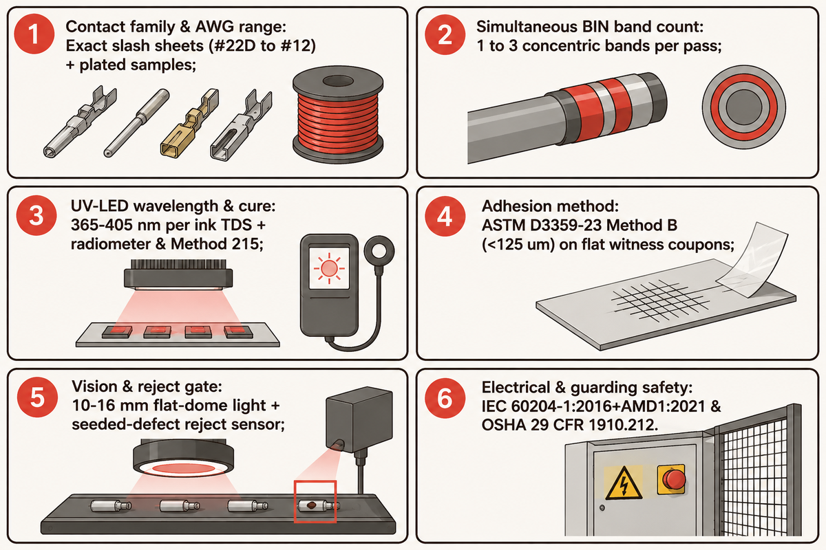
Contact geometry, closed-loop CCD vision, and band count all drive capital cost far more than frame footprint. Dedicated machines are built to your sample drawings, so exact machine costs require a custom quote and payback models should take into account both identification labor reductions and plant-measured rework escape risk.
Five Cost Drivers Behind Custom Coating Machine Quotations
Custom fully automatic color-ring cells are engineered around your drawings and batch requirements. Quotation scope is determined by the following design choices:
- Simultaneous color heads add synchronized applicators, individual metering drives, and wider UV exposure compared with a single-band head.
- Feeder and tooling scope escalates when plants move from one stainless bowl to interchangeable tracks, dowel-pinned collets, or magazine loaders needed to customize fragile Size #22D pin handling.
- Optical inspection tiers add multiple-viewpoint CCD cameras, diffuse flat-dome optics, color-sequence software, and sensor-verified reject diverters to reduce escapes of BIN errors.
- A matched quartz shield, UV-LED wavelength array, and process control alarm can be integrated for more consistent curing of pigmented inks.
- Controls engineering hours are added when PLC recipe lockout is integrated with barcode lot scanning and OPC-UA/MES logging.
Framing Payback Around Labor Reduction and Downstream Rework Context
Evaluating payback on operator hourly wages alone misses the downstream stakes on complex connector assemblies. On direct labor, ZEUEE’s published automation benchmark cites a typical reduction of >50% in identification labor when automating manual wire-assembly marking steps. Meanwhile, Connector Supplier reports that non-military builds using commercial-equivalent contacts, which omit QPL qualification, military testing, and BIN coding together, save an estimated 25–50% on contact unit cost. Qualified aerospace contacts therefore carry substantially higher per-piece value than commercial equivalents, increasing the financial impact of scrap.
System-level assembly testing metrics offer additional context on automated verification value. HooHA Wire & Cable’s custom assembly guide notes that high-volume automated test systems running 300–500 assemblies per hour achieve under 0.1% escape rates versus 2–3% with manual inspection. Laser Wire Solutions similarly reports that aerospace builds governed by NASA-STD-8739.4 and FAA/EASA rules incur costly rework, scrap, and re-certification delays whenever upstream defects escape into final assembly.
Payback worksheet example: HooHA has published escape-rate data for complete cable assembly testing and doesn’t isolate color-ring errors. Engineers should incorporate internal plant scrap logs into their model. Suppose verification moves from a 2% manual escape rate to 0.1% automated grading across a 10,000-unit annual batch. Escaped defects drop from 200 units down to 10 units, removing 190 late-stage teardown events per year alongside >50% lower direct marking labor. To understand the exact configuration of the machines described and the costs associated with them, refer to the ZEUEE automated color ring coating machine solutions and provide samples of parts for evaluation.
Copy the checklist below to your supplier RFQs to standardize the baseline against which all vendors will bid:
RFQ checklist — copy these into your quote request:
| Parameter | Recommended range | Why it matters | How to verify |
|---|---|---|---|
| Contact family & AWG range | Exact slash sheets (e.g., #22D 22–28 AWG to #12 12–14 AWG) | Sets collets, bowl lining vs magazine loader, and axial stop | Attach 2D drawings and send actual plated sample contacts |
| Simultaneous BIN band count | 1 to 3 concentric bands per pass (3 for full BIN) | Determines applicator head count and single-pass index rate | Measure multi-band width and gap tolerance on trial lot |
| UV-LED wavelength & cure check | Select wavelength (365–405 nm) per ink TDS; 395 nm often penetrates TiO2 white better when photoinitiator-matched | Through-cure requires ink-matched wavelength, film thickness, and dose; oxygen inhibition can still cause surface tack | Verify radiometer irradiance/dose log plus ink-specified cure and MIL-STD-202 Method 215 tests |
| Adhesion verification method | ASTM D3359-23 Method B (<125 µm) on flat witness coupons | Curved narrow contact rings cannot accept a flat cross-hatch grid | Run flat matching-plating coupons through the same machine cure |
| Vision lighting & reject gate | Diffuse flat-dome light (e.g., 10–16 mm thick panel per Vision Systems Design, aperture sized to FOV) + reject-confirmation sensor | Reduces metallic glare on curved pins and flags unconfirmed diverter strokes | Seed known defective pins at FAT and verify every seeded defect diverts with sensor confirmation |
| Electrical & guarding safety | IEC 60204-1:2016+AMD1:2021 (electrical); OSHA 29 CFR 1910.212 (U.S. guarding) | Applicable regional laws and buyer specs govern EHS sign-off | Audit electrical schematic, E-stop circuit, and enclosure door interlocks against contract scope |
Quotation boundary: Confirm whether custom contact tooling, vision calibration masters, and UV exhaust blowers sit inside the base quote before comparing bids.
Integration, Facility Utilities, and Equipment Qualification for Coating Lines
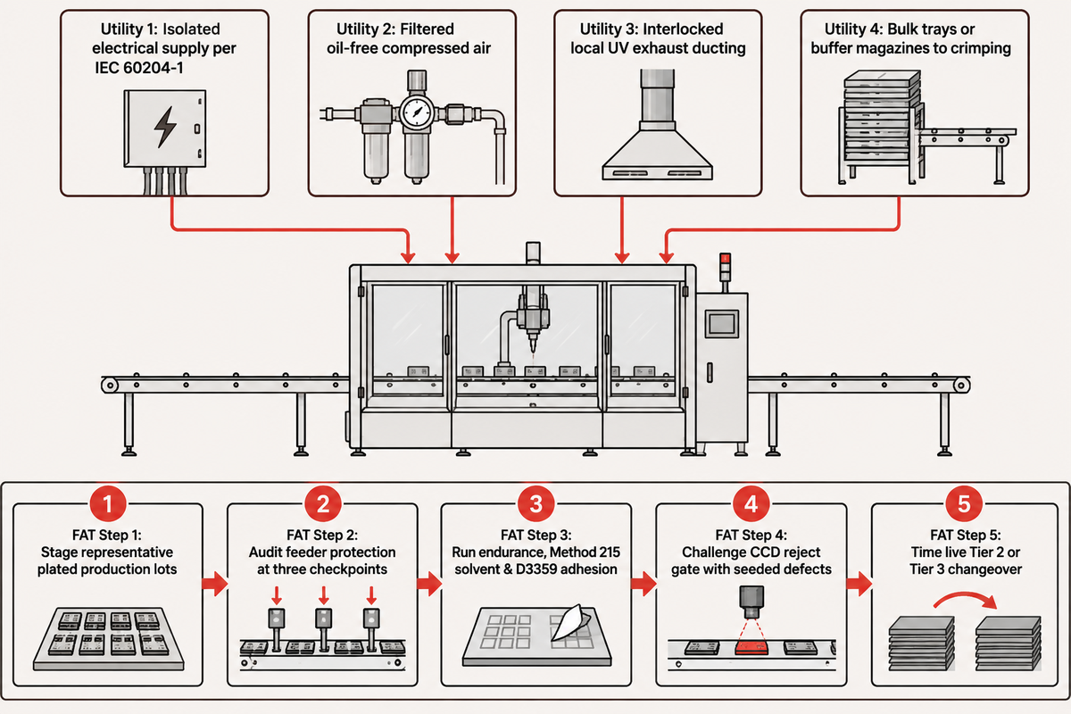
Launch delays do not always originate at the ink wheel. They happen when plant power, oil-free compressed air, UV exhaust ducting, and Factory Acceptance Test criteria remain unscoped until delivery. Locking down utilities and sample-based FAT protects production scheduling.
Pre-Installation Facility Utilities and Inline Coupling
Prior to rigging a coating cell onto the plant floor, plant facilities teams must prepare the four physical interfaces specified by the equipment OEM.
- Match plant voltage, phase, and breaker capacity at electrical supply entry per IEC 60204-1:2016+AMD1:2021, isolating vision and PLC power rails from inductive loads.
- Supply filtered, oil-free compressed air to chucks, escapements, and blow-off jets so airborne oil mist never contaminates gold plating.
- Connect local exhaust ducting interlocked to machine run status to vent monomer vapor and LED heat during continuous coating production.
- Decide whether the cell discharges into bulk trays or to a downstream connector crimping machine via buffer magazines to bridge refill stops.
Five-Step Factory Acceptance Test (FAT) Qualification Protocol
Following Lancing UK Bowlfeeders’ handover model, agree on representative samples, test duration, demand sequence, reject handling, and refill rules before delivery. Qualify every new color ring coating machine through five ordered steps:
- Stage representative plated contacts — supply production lots across your smallest and largest gauges instead of unplated dummy rods.
- Audit feeder protection at three checkpoints — inspect pin tips and gold finish after bulk loading, extended bowl recirculation, and linear track discharge.
- Run endurance, solvent, and adhesion checks — operate an uninterrupted endurance lot, then verify marking resistance to solvents via MIL-STD-202 Method 215 and flat-coupon coating adhesion via ASTM D3359-23.
- Challenge the CCD vision reject gate — seed reversed pins, smudged rings, and swapped BIN colors and confirm every defective pin diverts physically with sensor logging.
- Time a live Tier 2 or Tier 3 swap — clock technicians switching ink colors or contact sizes from last good pin to first verified good pin.
Catalogs in the public domain show dedicated contact coaters with CCD vision from ZEUEE (discrete contact cells), Adapt Automation (Model 1174 pin striper), and Yulishih (TIU-03 fuse-tube coater with CCD vision). Sample trials and FAT sign-off remain decisive. Buyers reviewing dedicated connector-automation capacity can inspect ZEUEE’s Shenzhen and Taihe automation engineering base. The operation spans a 20,000 m² Taihe campus, holds 150+ connector-automation patents, and exports across 30+ countries.
FAT sign-off rule: Base final delivery approval on seeded-defect vision catch logs and solvent-tested sample contacts from your own plated lots rather than dry-cycle video alone.
Frequently Asked Questions
What is a color ring coating machine used for in connector manufacturing?
In connector manufacturing, this machine applies up to three concentric identification stripes onto cylindrical pin and socket contacts. Three bands encode a complete three-digit SAE AS39029 Basic Identification Number (BIN). Automated cells combine oriented feeding, coaxial spin, metered UV-ink transfer, instant curing, and inline CCD checks to prevent wrong-gauge insertions.
How do you read the three color bands on an AS39029 pin or socket contact?
Read the three color bands in order from the wire-crimp barrel toward the mating tip. Each stripe maps to a standard resistor digit from 0 through 9, forming the contact’s three-digit Basic Identification Number. For example, Orange-Blue-Black identifies BIN 360 on M39029/58-360 contacts, confirming contact cavity size and wire gauge.
Which color ring coating machine configuration is best for mixed M39029 contact batches?
High-mix M39029 shops perform best with a three-head rotary cell using quick-release pre-inked cassettes, dowel-pinned contact tooling nests, and barcode-locked vision recipes. Pairing soft-lined bowls or magazine loaders with ink-matched UV-LED curing and flat-dome CCD optics cuts changeover downtime while protecting delicate Size #22D gold-plated pins.
How much does an industrial color ring coating machine typically cost?
Industrial color ring coating machines carry no published list price and require a custom RFQ. Budget scales with contact diameter range, simultaneous band count, feeder type, and CCD inspection tier. Separate base machine, per-size tooling nests, vision masters, and UV exhaust on every bid.
Can an automated color ring coater replace a laser or inkjet wire marking machine?
No, each machine serves a different marking geometry and compliance goal. Fiber lasers and continuous inkjet printers excel at fast alphanumeric lot codes, 2D barcodes, and legends on continuous cable jackets or flat connector shells. Lasers, however, don’t produce standardized multi-color resistor bands on thin 0.000050 in gold plating, and standard inkjet printheads require specialized rotary integration to band miniature discrete pins cleanly. Connector plants typically run rotary ring coaters alongside laser or inkjet stations.
What sample materials should buyers send for a color ring coating machine trial?
Send actual plated production contacts across every target size, 2D part drawings marking mating keep-out zones, your required M39029 BIN color codes, and your MIL-STD-202 Method 215 solvent specification. Include flat matching-plating witness coupons whenever ASTM D3359-23 adhesion grading is required.
Need a Technical Feasibility Review for Your Contact Drawings?
What’s your contact gauge range? What are your BIN color sequences? What are your inspection tolerances? Share these with our engineering team to scope sample trials, tooling changeover layout, and Factory Acceptance Test (FAT) criteria.
Reviewed by the Shenzhen Zeyu Intelligent Industrial Science Technology Co., Ltd technical team. This guide uses public standards, published patent mechanisms, independent laboratory synopses, and labeled engineering calculations. Release for production is based on product drawings, ink data sheets and Factory Acceptance Tests.
References & Sources
- CN118744073A, Automatic Contact Color Ring Coating Apparatus (2024) Google Patents (Shanghai Workpower Telecom Co., Ltd.)
- CN122558722A, Cylinder Shaft Automatic Color Coating Ring Device (2026) Google Patents (Kunshan Aisyitian Automation)
- US6311229B1, Color Coding Identification System for a Block I/O System (Expired) Google Patents (Elsag International BV)
- An Exploration of AS39029, Part 1 (2025) Lectromec (ISO/IEC 17025 Testing Laboratory)
- M39029 Contacts: Plating, QPL, and BIN Identification Guide Connector Supplier
- Measuring UV Curing Parameters of Commercial Photopolymers (Updated May 2026) National Institute of Standards and Technology (NIST), U.S. Department of Commerce
- ASTM D3359-23, Standard Test Methods for Rating Adhesion by Tape Test ASTM International
- Flat Dome Lights Tame Reflections and Shadows in Machine Vision (2020) Vision Systems Design
- IEC 60204-1:2016+AMD1:2021, Safety of Machinery: Electrical Equipment of Machines (6th Edition) International Electrotechnical Commission (IEC)
- 29 CFR 1910.212, General Requirements for All Machines Occupational Safety and Health Administration (OSHA), U.S. Department of Labor
WHY WE WRITE THIS
About ZEUEE Engineering Insights
ZEUEE shares technical guides based on real automation project experience. Since 2005, we have designed and manufactured non-standard automation equipment for connector assembly, wire harness production, robotic lines, vision inspection, and smart factory upgrades.
Founded in 2005
20,000 m² production base
120+ specialists
150+ R&D patents
ISO9001:2015 certified
Trending now