Get in touch with Zeyu lntelligent Industrial Company

Inside the Twist-Pin Expansion Machine: Waist-Bulge Engineering, Failure Modes, and Tolerance Stack-Up

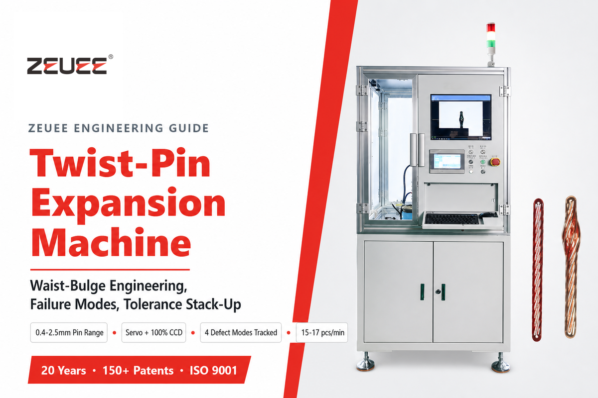
A twist pin expansion machine is the single production station that forms the waist bulge on a beryllium-copper twist-pin contact, also written twist-pin expansion machine or sold as a twist pin automatic expansion machine given its servo-driven, hands-off cycle — distinct from the braiding station that winds the strands, the welding station that terminates them, and the insertion equipment that seats the finished pin into a connector shell. It isn’t a fastener-expander system, a PEX plumbing tool, or a shipping-container twistlock machine — three unrelated products that share overlapping search terms. This guide is about the connector-manufacturing machine: the servo-driven, CCD-inspected station that turns a welded strand bundle into a hyperboloid contact with a controlled, repeatable mating force.
Most engineering teams evaluating a twist-pin expansion station already know the machine exists — what they don’t have is a way to translate a bulge-diameter tolerance band into a mating-force number, or to trace a CCD reject back to the process parameter that actually caused it. That’s the gap this guide fills.
Quick Specs, Expansion Station Parameter Reference
| Pin diameter range | 0.4 mm (signal/Nano-D) to 2.5 mm (power contacts) |
| Throughput (single station) | 15-17 pcs/min |
| Inspection coverage | 100% in-line CCD, 4 tracked defect modes |
| Forming mechanism | Servo-driven anti-helical rotation (not cam-driven) |
| Feedstock heat state | Beryllium-copper (C17200), tempered at the bulge post-forming |
| Mating-cycle target | Up to 100,000 cycles (hyperboloid contacts, industry benchmark) |
Figures above reference ZEUEE’s C49-ZY05-01 twist-pin expansion machine spec sheet and independently published hyperboloid-contact industry data (sources below).
1. What a Twist-Pin Expansion Machine Does (And What It Isn’t)
A twist-pin expansion machine forms the waist bulge that turns a welded bundle of beryllium-copper strands into a self-sprung hyperboloid contact, and it’s one of six distinct stations in a complete twist-pin production line — not a synonym for the whole line. Strand pay-off, cutting, and welding happen upstream; alignment and final inspection happen downstream. The expansion station’s specific job is to rotate the welded cage anti-helically, untwisting it just enough to bulge the waist outward to a controlled diameter, which is the geometry that actually sets the contact’s mating force.
Search results for “twist pin expansion machine” are dominated by unrelated products — upholstery twist pins, PEX-plumbing auto-rotation expansion tools, and shipping-container twistlock handling machines all use overlapping vocabulary. None of those are connector-manufacturing equipment. If your team supplies MIL-DTL-32139 (Nano-D) or MIL-DTL-83513 (Micro-D) qualified contacts, or you’re evaluating whether to bring bulge-forming in-house, the machine this guide covers is a single-station cell that sits between the welding station and final inspection in a hyperboloid-contact production line.
Who Actually Needs This Station?
Connector OEMs already running a stranding-and-welding line who are adding in-house bulge-forming capacity; contract manufacturers qualifying a new hyperboloid-contact product line; and process engineers auditing why an existing cam-driven or manual bulging step is producing inconsistent mating force. Typical end markets span automotive, aerospace, and appliance connector programs, where mating-force consistency after installation in the field matters as much as it does on the production floor.
If you’re buying finished twist-pin contacts rather than building your own line, the build-vs-buy framework in Section 10 is the more relevant starting point.
2. Inside the Anti-Helical Bulge: The Physics of Waist Formation
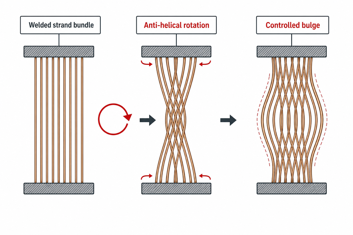
A servo-driven expansion head forms the hyperboloid waist by rotating the welded strand bundle’s clamped ends against each other — an anti-helical motion that untwists the strands just enough to make each one bow outward into a controlled bulge, rather than by pushing or stamping the bundle into shape. U.S. Patent 6,584,677 B2 describes this directly: the twist-pin bulge is formed by rotating clamp members anti-helically to untwist the strands, after which heat treatment tempers the beryllium-copper at the bulges to set its spring shape. That sequencing matters — the bulge geometry is set mechanically first, and the temper that locks in the spring force is applied after, at the bulge, not upstream in bulk material processing (see Section 3 for the metallurgy). This is also why servo torque specs matter as much as angular position: the motor has to hold consistent rotational force through the full anti-helical stroke, not just hit a target angle, or the bulge diameter drifts even when the program looks correct on paper.
Redundant contact is the reason this specific geometry needs a dedicated machine rather than a stamping die. Ten helically wound strands, once bulged, create seven to ten independent line-contact points against the mating pin instead of the two or three point-contacts a stamped socket delivers. Hyperboloid contact technology was invented in 1956 by Francois Robert Bonhomme for railway signaling applications that needed connections to survive constant shock and vibration — a lineage that later carried the technology into military, aerospace, and test-and-measurement equipment where the same redundant-contact principle now delivers up to 100,000 mating cycles without a measurable rise in contact resistance — a fatigue-life margin consistent with peer-reviewed rotating-bending fatigue data for C17200 beryllium copper.
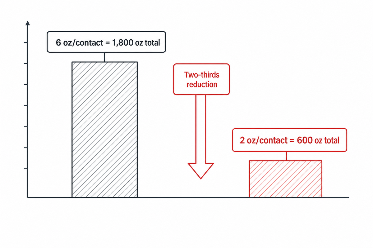
“If you have a 300 position connector, and each contact is six ounces, that’s 1,800 ounces (112 lbs) of force, which is a substantial load to mate the connector. If that can be reduced to approximately two ounces per contact, you have reduced the force to engage the connector by two-thirds.”
That force math is the real argument for precision bulge-forming: at high pin counts, small per-contact force reductions compound into a mating-force budget the connector housing and latch hardware actually have to survive. Section 4 walks through the same arithmetic against ZEUEE’s own contact family.
Waist-Bulging vs. Parallel Pin Expansion
Q: Is a twist-pin expansion machine the same as parallel pin expansion tooling?
No — parallel pin expansion is a mechanical fastener/tube-expansion technique where rolls run parallel to a mandrel at zero feed angle, unrelated to hyperboloid contact forming.
“Parallel pin expansion” is industrial terminology for expanding tube or pin fasteners using rolls set parallel to a mandrel with zero feed angle, so the mandrel is pushed through the expander by force — a mechanical fastening technique used in tube-and-fitting work. Machines sold as parallel pin expanders perform this different, mechanical fastening task; they share vocabulary with twist-pin waist-bulging but run a different physical process on different materials for a different industry. If your search led you here from a “parallel pin expansion” query, you likely want tube-expansion tooling, not connector contact-forming equipment.
3. Why the Bulge Needs Its Own Heat-Treatment Step
The waist bulge needs a dedicated temper step because the mechanical act of bulging alone doesn’t lock in the spring force that gives a hyperboloid contact its mating characteristics — that requires precipitation-hardening the beryllium-copper after the geometry is set. Per U.S. Patent 6,584,677 B2’s own process description, heat treatment is applied at the bulge, after the anti-helical rotation forms it, specifically to set the spring shape. Skip or under-run that step and the bulge holds its shape immediately after forming but loses spring-back consistency in service.
Beryllium copper’s precipitation-hardening response is well characterized: the Copper Development Association’s published data for C17200 shows a precipitation-hardened (TF00) temper reaching roughly 175 ksi tensile strength, 155 ksi yield strength, and 6% elongation, against a solution-treated (TB00) baseline of only about 70 ksi tensile / 32 ksi yield / 45% elongation for the same alloy. That precipitation treatment runs at 600°F for 3 minutes in air, following a solution treatment at 1,425-1,475°F for 0.5 minutes in water.
⚠️ Important, Material Form Matters
The temper table above is published for C17200 in plate, sheet, strip, and rolled-bar form under ASTM B194. Stranded wire that actually feeds a twist-pin expansion machine is governed separately by ASTM B197/B197M (copper-beryllium alloy wire). Temper designations and the precipitation-hardening logic carry across both forms, but the exact numeric values for your specific wire lot should come from the mill test certificate against B197, not assumed directly from B194 sheet data.
In practice, this means a Mill Test Certificate for the incoming BeCu wire should specify heat-treat state explicitly (a code like TF00 or TH04, not just “hardened”), and a supplier who can’t tell you which temper condition their wire ships in — or which station in their line applies the post-bulge treatment — isn’t someone who controls the process end to end.
4. From Bulge Diameter to Mating Force: The Tolerance Stack-Up
Bulge-diameter tolerance translates directly into mating-force budget because every contact’s individual force adds up across the full pin count — a small per-pin tolerance drift becomes a large total-engagement-force problem at high pin density. ZEUEE’s own C49-ZY05-01 spec for a 51-position Micro-D connector puts the reference figure at roughly 6 ozf (1.67 N) per contact, which compounds to more than 85 N of total engagement and disengagement force across the full connector — a number an operator has to physically overcome by hand or with tooling on every mate cycle.
📐 The Force-per-Micron Rule, Worked Example
Take the QA Technology reference point: a 300-position connector at 6 oz/contact totals 1,800 oz (112 lb) of engagement force. Cutting the per-contact force to roughly 2 oz — achievable with a tighter, more consistent bulge diameter — cuts total engagement force by two-thirds, to about 600 oz (37.5 lb). Scale that logic down to ZEUEE’s 51-position Micro-D reference (6 ozf/contact, ~85 N total): every micron of uncontrolled bulge-diameter drift that pushes a contact toward the high end of its force band adds up across the full pin count, not just at one pin. That’s the arithmetic a servo+CCD station is actually selling: not a nicer machine, but a narrower, provable distribution around the target force per contact.
Figures: QA Technology Company (via Connector Supplier, 2022/2024) and ZEUEE C49-ZY05-01 solution-page specification.
What geometric tolerance can’t do is guarantee the finished connector qualifies on its own — for MIL-DTL-32139 programs specifically, bulge tolerance is only one input into the broader connector-level dimensional envelope discussed in Section 9. Bulge geometry sets the mating-force budget; final connector qualification also depends on vibration resistance, thermal cycling, humidity exposure, and corrosion behavior — factors this single station doesn’t control and can’t inspect for. A perfectly toleranced bulge on a contact plated with the wrong gold thickness, or assembled into a shell with a marginal seal, still fails qualification. Treat the expansion station’s tolerance data as one input to a qualification decision, not the whole decision.
5. One Station, Six Pin Classes: Tuning Bulge Parameters from 0.4 mm to 2.5 mm
ZEUEE’s C49-ZY05-01 is speced to form bulges across six pin-diameter classes on a single platform, from 0.40 mm Nano-D signal pins up to 2.5 mm large power contacts — a vendor-published operating envelope, not an independently benchmarked industry standard, so treat the class boundaries below as this specific machine’s spec rather than a universal engineering ceiling.
| Pin class | Nominal pin diameter | Controlled parameters | CCD reject trigger |
|---|---|---|---|
| Nano-D signal | 0.40 mm | Swell diameter, swell length, concentricity | Out-of-band diameter/length; tilted head |
| Nano-D (M32139 typical) | 0.635 mm | Swell diameter, swell length, concentricity | Out-of-band diameter; separated strand |
| Micro-D class | 0.76 mm | Swell diameter, swell length, concentricity | Uneven swell profile; damaged thread |
| Micro-D / power | 0.80 mm | Swell diameter, swell length, concentricity | Out-of-band diameter; tilted head |
| Power contact | 1.00 mm | Swell diameter, swell length, concentricity | Uneven swell; separated strand |
| Large power | up to 2.5 mm | Swell diameter, swell length, concentricity | Out-of-band diameter/length |
Two things change as pin diameter climbs from signal to power class: the absolute force budget scales up (more wire cross-section means more spring force per contact, per the Force-per-Micron Rule above), and the CCD’s dimensional tolerance band has to widen proportionally to avoid false rejects on larger, inherently more variable bulges. A vendor who quotes one static tolerance band across all six classes is quoting marketing copy, not a tooling spec — ask for the class-specific band on your contact drawing.
6. Root-Causing the Four Expansion Defect Modes
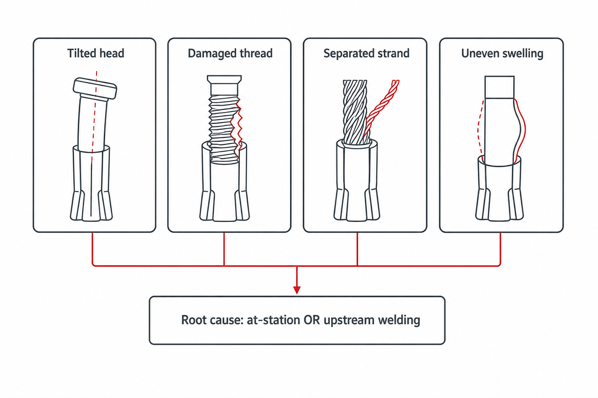
Each of the four named expansion defect modes — tilted head, damaged thread, separated strand, and uneven swelling — traces back to a specific process parameter rather than a generic “quality issue,” and diagnosing which one requires knowing where in the station the fault actually originates, not just what the CCD flagged.
| Defect Type / Class (CCD name) | What’s physically wrong | Most likely root cause | Diagnostic check | Limitations / not conclusive when |
|---|---|---|---|---|
| Tilted head — at-station cause | Pin head off-axis after expansion | Clamp not concentric to servo rotation axis | Check clamp alignment before adjusting the expansion program | Rules out only the clamp; feeder and upstream causes still possible |
| Tilted head — upstream cause | Same symptom, different origin station | Feeder wear (check on pre-run inspection), or strand already bowed from stranding-stage tension variance | Check feeder wear log and stranding-stage tension trend before assuming an expansion-station fault | Only distinguishable from the at-station cause with a documented feeder-wear schedule |
| Damaged thread — at-station cause | Torn or deformed strand surface at the swell zone | Excess clamp force or misapplied bulge program for the pin class in use | Verify program matches actual pin class loaded (Section 5) | Not diagnostic if incoming wire already had surface defects from drawing/stranding |
| Damaged thread — upstream cause | Same symptom, different origin station | Wire-surface defect introduced at drawing or stranding, before the strand ever reaches expansion | Cross-section a rejected sample against the incoming wire’s own mill inspection record | Requires incoming-wire inspection data most shops don’t keep per lot |
| Separated strand | One or more wound strands pulled loose from the bundle | Incomplete or off-axis weld at the upstream welding station, not the expansion station itself | Trace back to the weld-station CCD/inspection record for that unit before adjusting expansion parameters | A pattern here signals a welding-station problem, not an expansion-station one |
| Uneven swelling — servo-driven line | Asymmetric or out-of-tolerance-band waist diameter | Servo rotation program drift or miscalibration | Run a CMM spot-check against the CCD’s own calibration to rule out sensor-side drift | Not conclusive without a documented CCD-to-CMM correlation record for that shift |
| Uneven swelling — cam-driven line | Same symptom, mechanical-wear origin | Mechanical wear in the cam profile drifting the bulge diameter over a production run | Check cam-profile wear against its maintenance interval, not just the current part | Cam wear is progressive — a single good part doesn’t rule it out for the next shift |
| Any defect, clustered pattern | Multiple defect types spiking together on one shift | Points to a shared upstream cause (bad wire lot, weld-station drift) rather than four independent expansion-station faults | Cross-reference defect timestamps against lot changes and upstream-station maintenance logs | Requires lot-level traceability through the whole line, not just the expansion station |
| Any defect, isolated single unit | One part fails, surrounding parts pass | Most likely a one-off feedstock or handling anomaly, not a systemic process shift | Log and monitor; don’t re-tune the whole program off a single data point | Re-tuning on single-unit noise is itself a common source of induced process drift |
Two verification layers back this up in production. In real time, the station’s own CCD vision system measures swell diameter and length on every part and automatically diverts anything outside the programmed tolerance band; periodically, an offline CMM or optical-comparator spot-check cross-validates the CCD’s own calibration against a traceable dimensional standard. A buyer auditing a supplier should ask for both the CCD reject-rate log and the CMM correlation record — not just one or the other, since a drifting CCD will pass its own bad calibration silently.
Wear-related failure downstream of a “passing” bulge is a separate, cumulative issue rooted in the same C17200 fatigue behavior that governs the bulge itself: gold-plating thickness on the finished contact governs how many mating cycles it survives before wear-through starts raising contact resistance. One contact-pin supplier’s published reference figures for gold-flash-to-cycle-life put a 3-6 microinch flash at roughly 50 cycles, climbing to about 500 cycles at 50 microinch — a general connector-industry rule of thumb, not a hyperboloid-specific or MIL-spec-mandated figure, so confirm the actual number against your own contact drawing and plating vendor’s certification rather than treating it as a universal constant.
7. Servo vs Cam-Driven vs Manual Bulging: Where Each One Actually Fails
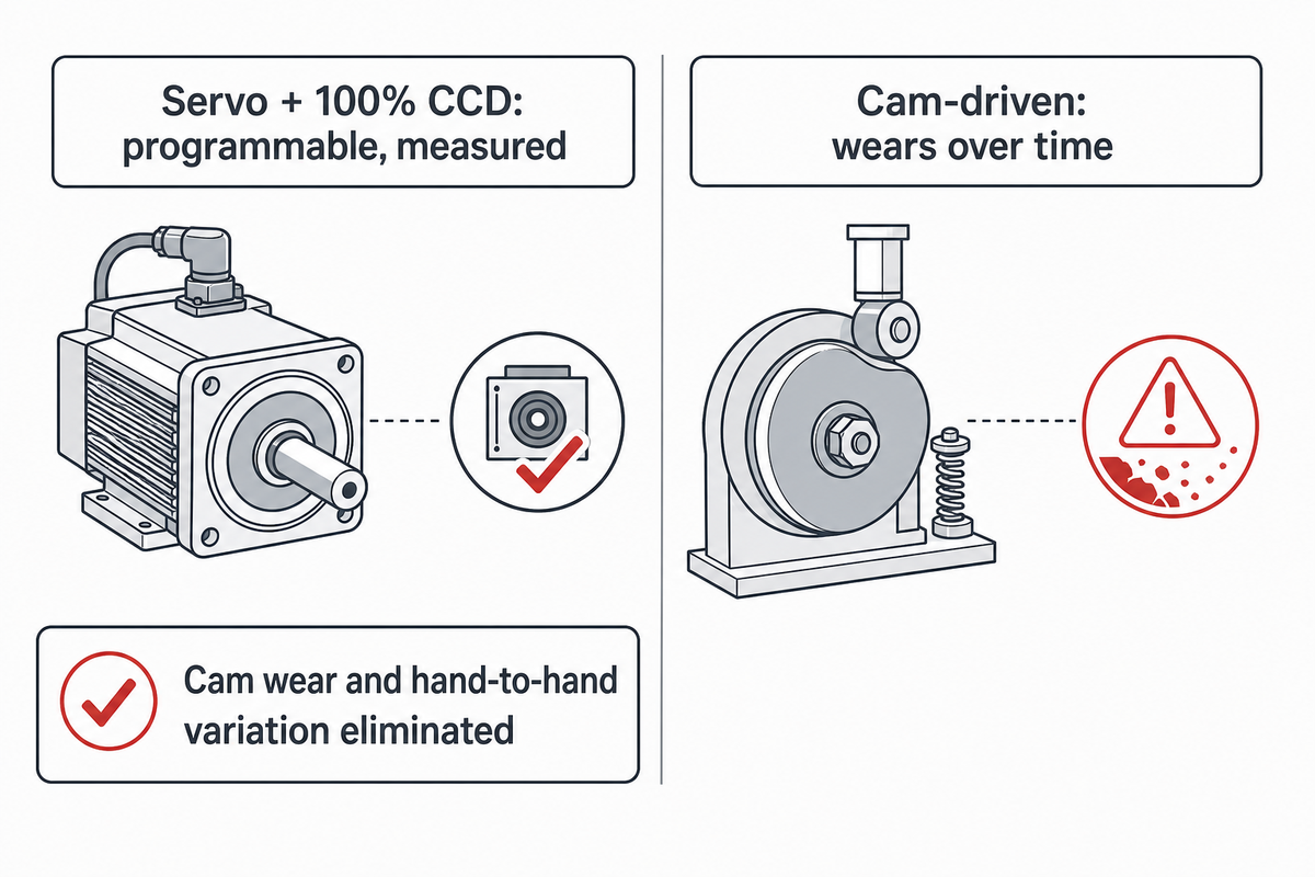
Servo-driven bulging with 100% CCD inspection fails less often than cam-driven or manual bulging not because it’s inherently more precise in a single cycle, but because it converts an operator-dependent process into a programmable, measured one — cam wear and hand-to-hand variation are the specific failure modes it eliminates, and the narrower, repeatable tolerance band is what lets first-pass yield increase without adding inspection headcount. Automation also raises the practical speed ceiling: a well-tuned servo station can run at high speed without the diameter drift that forces a manual operator to slow down, and the tighter tolerance band helps reduce the stress concentration that shortens contact life — minimizing rejects while keeping the line closer to its maximum throughput.
✔ Where servo + CCD wins
- Bulge dimension is a programmable parameter, not a fixed-tool geometry
- 100% in-line inspection catches defects at the part, not by sampling
- Changeover between pin classes is a program change, not a tooling swap
⚠ Where cam-driven and manual still fail
- Cam-driven: mechanical wear in the cam profile drifts the bulge diameter silently over a production run, with no automatic flag
- Manual: bulge consistency depends on operator technique and fatigue, and inspection is typically sampled, not 100%
- Both: a diameter change means a physical tooling swap, not a program edit
📐 The Escaped-Defect Break-Even
A cam-driven or manual station’s real cost isn’t its lower purchase price — it’s the defect rate that gets past sampled inspection and shows up as a customer mating-test failure instead of an in-house reject. That economic crossover happens when the cost of one escaped defect (a failed connector in a customer’s assembly, plus the root-cause investigation) exceeds the price gap between a servo+CCD station and a cam-driven one, multiplied by how many units that gap buys. For MIL-spec or other high-reliability programs where a field failure triggers a formal corrective-action process, that crossover point arrives fast; for a low-consequence commercial application with generous mating-force tolerance, cam-driven or manual can legitimately stay the better economic choice. Run the comparison against your own escaped-defect cost, not a vendor’s throughput brochure.
8. Where Expansion Sits in the Line — And What Breaks When It’s Misaligned
The expansion station sits downstream of strand pay-off, cutting, and welding, and upstream of alignment and final inspection — and a problem introduced upstream doesn’t stay upstream, because the expansion station can only work with the geometry the welding station hands it.
If the upstream welding station leaves a strand incompletely bonded or slightly off-axis, the expansion station’s CCD will most likely flag it as a “separated strand” or “tilted head” defect at the bulge stage — not because the expansion station caused the fault, but because that’s the first point in the line with 100% inspection coverage tight enough to catch it. This is why the root-cause matrix in Section 6 explicitly separates “expansion-station cause” from “trace back to welding station” — treating every CCD reject at the bulge stage as an expansion-station problem sends maintenance chasing the wrong equipment.
Expansion itself is a cold-forming operation — it doesn’t cut, weld, or grind, so it doesn’t generate the beryllium-copper dust or fume that create occupational-exposure risk under OSHA guidance for fabrication and machining operations. That exposure risk concentrates at the upstream stranding, cutting, and welding stations, and at any downstream trimming or finishing step — worth flagging to EHS when scoping a full line, even though it isn’t a concern specific to the expansion station itself.
On the tooling side, ZEUEE’s C49-ZY05-01 keeps the feeder, clamp, expansion head, and CCD module on independent access panels specifically so a plant that changes pin types dozens of times a year isn’t tearing down the whole cell for every changeover — a detail worth confirming on any vendor’s cell, since it directly affects changeover time when you’re running mixed pin classes through one station.
9. The Standards Clauses That Actually Govern the Bulge (Not the Whole Connector)
No single standard is written specifically for the twist-pin expansion step — the clauses that bear on it come from two different documents covering two different things, and knowing which one covers what prevents citing “MIL-spec compliant” as if it were one blanket approval.
MIL-DTL-32139 (the detail specification for nanominiature/Nano-D connectors) sets dimensional and angular tolerance bands at the connector-and-contact level — its published slash sheets specify tolerances such as ±.005 inch (0.13 mm) with ±2° angular tolerance unless otherwise noted on the specific sheet. That’s a connector-level dimensional envelope the finished, bulged contact has to sit inside — it isn’t a bulge-forming process spec.
IPC/WHMA-A-620 is the workmanship side, and it’s important to cite the current edition: IPC/WHMA A-620F-2025 supersedes A-620E-2022 as of its release, and officially makes the E edition obsolete as the current reference. The standard defines three Product Classes (Class 1 general electronic products, Class 2 dedicated-service products, Class 3 high-performance/harsh-environment products for safety-critical and mission-critical applications) and governs materials, methods, and acceptance criteria for crimped, mechanically secured, and soldered interconnections. It explicitly does not provide criteria for cross-section or X-ray evaluation — a scope boundary worth knowing before assuming A-620 alone covers your incoming-inspection plan for bulged contacts.
RFQ checklist — copy these into your quote request for a twist-pin expansion station:
| Parameter | Recommended range | Why it matters | How to verify |
|---|---|---|---|
| Pin diameter coverage | Match your full product mix, e.g. 0.4-2.5 mm | One station covering fewer classes means more tooling swaps | Request the class-specific tolerance table, not a single headline range |
| CCD defect coverage | All 4 modes: tilted head, damaged thread, separated strand, uneven swelling | Partial coverage lets defects escape to final test | Ask for the per-defect reject-rate log, not a single aggregate yield number |
| CCD-to-CMM correlation | Documented, periodic | An uncalibrated CCD can pass bad parts silently | Request the correlation record, not just a calibration certificate |
| Heat-treat state on incoming wire | Explicit temper code (e.g. TF00, TH04) against ASTM B197 (wire) | Vague “hardened” claims can’t be audited | Require the Mill Test Certificate on file, referencing wire spec not sheet spec |
| Throughput at your target pin class | Verified pcs/min at full CCD inspection on | Bypass-mode marketing rates overstate real output | Ask for line-rate data with inspection enabled, not a bypass-mode number |
10. Should You Add an Expansion Station, or Buy Finished Bulged Pins?
Add an in-house expansion station when bulge-diameter consistency is a qualification-critical variable you need direct control over and your volume justifies the capital; keep buying finished contacts when your volume is low or your program doesn’t depend on tracing every defect back through your own process data.
ZEUEE doesn’t publish a flat twist pin expansion machine price online — like most non-standard automation equipment, the price depends on pin-class coverage and integration scope, so treat the RFQ checklist below as the fastest route to an actual quote rather than comparing twist pin expansion machine manufacturers on list price alone.
| Factor | Favors buying finished contacts | Favors adding a station in-house |
|---|---|---|
| Volume | Low, sporadic, or prototype-stage | Sustained production across multiple programs |
| Traceability need | Supplier’s own qualification data is acceptable to your customer | Your program requires per-lot, per-station process data you control |
| Pin-class mix | Narrow, standard classes readily available off the shelf | Custom or mixed classes a single flexible station can cover |
| Escaped-defect cost | Low-consequence application, generous mating-force tolerance | High-reliability program where a field failure is expensive (see Section 7) |
| Standards/compliance ownership | Supplier’s A-620F and MIL-DTL-32139 documentation is accepted as-is (Section 9) | Your quality team needs to own the compliance documentation directly |
| Heat-treat traceability | A supplier’s Mill Test Certificate on file is sufficient (Section 3) | You require per-lot MTC review against ASTM B197 in-house |
| Changeover frequency | Infrequent pin-class changes; supplier lead time is acceptable | Frequent pin-class changeovers where supplier lead time creates a bottleneck |
| Capital budget | Limited capex available for tooling right now | Capex is available and justified by sustained volume |
| Line integration complexity | Finished contacts integrate cleanly into an existing assembly line | The expansion station needs tight integration with your existing six-stage line (Section 8) |
If the balance points toward building in-house, the specification work in Sections 5 and 9 — pin-class coverage, CCD defect coverage, and the standards clauses that actually apply — is what turns a vendor conversation into an RFQ your quality team can sign off on. ZEUEE’s C49-ZY05-01 covers the 0.4-2.5 mm range described throughout this guide with 100% CCD inspection across all four tracked defect modes; if you’re scoping a station against that spec, the C49-ZY05-01 twist-pin expansion machine page has the full servo-vs-cam-vs-manual comparison data and RFQ contact details.
For the bigger picture of where expansion fits into the complete six-station line — stranding, cutting, welding, expansion, alignment, and inspection — see ZEUEE’s complete twist-pin manufacturing guide. If your program is specifically Nano-D (MIL-DTL-32139), the Nano-D buyer’s guide covers the 7-question buyer filter and shell-size selection in more depth than this guide’s single-station focus.
Frequently Asked Questions
Q: What’s the difference between the expansion/bulging step and the braiding step?
Braiding winds the raw strands into the hyperboloid cage shape; expansion bulges that welded cage outward to set the final mating force. The two stations are sequential, not interchangeable, and confusing them during a process audit sends troubleshooting to the wrong station.
The braiding station (Stage 1 of the six-stage line) winds ten beryllium-copper strands into the raw hyperboloid cage geometry, setting the helix pitch and lay length that determine how the finished contact will flex. The expansion (bulging) station comes two stages later, after the strand ends are welded: it takes that welded cage and rotates it anti-helically to untwist and bulge the waist outward to a controlled diameter, which is what actually sets the contact’s mating force and insertion resistance. Braiding shapes the cage; expansion sets how hard it grips.
Q: How is bulge diameter actually measured on a production line?
Two ways: real-time 100% CCD inspection during forming, plus periodic offline CMM spot-checks to validate the CCD’s own calibration. Buyers evaluating a supplier should ask for both records, not just one.
Bulge diameter is verified two ways on a production line: in real time by the station’s own CCD vision system, which measures swell diameter and length on every part as it forms and automatically diverts anything outside the programmed tolerance band to a reject bin; and periodically by an offline CMM or optical comparator spot-check, which cross-validates the CCD’s calibration against a traceable dimensional standard. Buyers auditing a supplier should ask for both the CCD reject-rate log and the CMM correlation record, not just one or the other.
Q: What causes a bulge to form off-axis (tilted head)?
Almost always a clamp or feeder alignment issue upstream of the forming action itself, not the servo program. The fix is checking upstream clamp wear and strand tension, not retuning the bulge parameters.
A bulge forms off-axis, showing up on inspection as a tilted head defect, almost always because the contact was not clamped concentric to the servo rotation axis before forming began, often from wear in the feeder or a clamp-alignment issue found on pre-run inspection, or from a strand that was unevenly tensioned during the upstream stranding stage and enters the bulge station already slightly bowed. Because the defect originates before the bulge is even formed, tightening the expansion station’s own tolerance band does not fix it; the fix is upstream, checking clamp wear and stranding-stage strand tension first.
Q: Can an existing manual/cam bulging line be retrofitted to servo?
Usually yes, as a station rebuild rather than a simple repair or bolt-on kit — expect to replace the servo head, drive electronics, and CCD module while reusing the existing frame and feeder section.
Usually yes, as a station rebuild rather than a bolt-on kit: the servo head, drive electronics, and CCD module replace the cam mechanism, reusing the frame and feeder.
Q: How much throughput does the expansion station need if the rest of my line runs faster?
Match it to your line’s actual bottleneck, not to the expansion station’s rated ceiling — adding capacity anywhere else is wasted spend until the true bottleneck station is identified.
Match it to your line’s actual bottleneck, not to the expansion station’s rated ceiling. A single C49-ZY05-01-class station runs 15-17 pieces per minute; if your upstream stranding and welding stations or your downstream inspection and insertion equipment cap out lower than that, adding a second parallel expansion cell buys you nothing until you raise the slower stage first. Conversely, if every other station in the line already clears 20+ pieces per minute, a single expansion station becomes the bottleneck and is the correct place to add parallel capacity rather than upgrading stations that are not actually limiting throughput.
Why We Write This
ZEUEE’s own engineering team designs and builds the C49-ZY05-01, the station this guide is built around, so the tolerance-to-force math and defect root-cause logic here comes directly from how that machine is specified and inspected — cross-checked against independently published metallurgy and connector-industry data, not just internal spec sheets.
This guide covers the twist-pin expansion (waist-bulging) station specifically — the process-engineering depth of a single station, not a survey of the whole twist-pin production line. Where the underlying evidence was vendor-specific or limited to one material form, we’ve said so rather than presenting it as universal fact. Reviewed by the Shenzhen Zeyu Intelligent Industrial Science Technology Co., Ltd technical team.
References & Sources
- MIL-DTL-32139 Detail Specification U.S. Defense Logistics Agency, Land and Maritime
- C17200 Alloy Data, Copper Beryllium Wrought Copper Development Association
- Rotating Bending Fatigue Behaviors of C17200 Beryllium Copper Alloy at High Temperatures peer-reviewed materials science journal, via NCBI/PMC
- IPC/WHMA A-620F-2025 Workmanship Standard (Cable and Wire Assemblies) ANSI
- Hyperboloid Contact Technology Is Still Going Strong Connector Supplier
- US Patent 6,584,677 B2, Method of Untwisting Strands to Form a Hyperboloid Electrical Contact USPTO
Related Articles
- ZEUEE C49-ZY05-01 Twist-Pin Expansion Machine full specification, servo/cam/manual comparison, and RFQ
- Twist Pin Machine: A Complete Manufacturing Guide the full six-station production line
- Nano Twist Pin Machine: Buyer’s Guide for Nano-D MIL-DTL-32139-specific buyer filter and shell-size selection
- Connector Assembly Machines Catalog ZEUEE’s full connector equipment range
WHY WE WRITE THIS
About ZEUEE Engineering Insights
ZEUEE shares technical guides based on real automation project experience. Since 2005, we have designed and manufactured non-standard automation equipment for connector assembly, wire harness production, robotic lines, vision inspection, and smart factory upgrades.
Founded in 2005
20,000 m² production base
120+ specialists
150+ R&D patents
ISO9001:2015 certified
![Automated Screwdriving: Torque & Cycle Time [Guide]](https://zeueeauto.com/wp-content/uploads/2026/10/automated-screwdriving-featured-768x512.png)

![Automated Screwdriving: Torque & Cycle Time [Guide]](https://zeueeauto.com/wp-content/uploads/2026/10/automated-screwdriving-featured-150x150.png)