Get in touch with Zeyu lntelligent Industrial Company

Optical Connector Assembly Line FAT and Validation Guide


Factory acceptance • measurement agreement • traceability
Optical connector assembly lines shouldn’t pass Factory Acceptance Tests just because they produce a few acceptable connectors while the line is being supervised. An optical connector assembly line is a linked production system that prepares, assembles, inspects, tests, identifies, and records defined fiber-connector variants under controlled recipes. Successful FAT evidence should demonstrate that the agreed upon scope, measurement methods, challenge samples, unusual responses, changeovers, logs, and release conditions are aligned.
Short answer: freeze what will be built and how it will be judged; correlate the buyer’s and supplier’s measurement systems; challenge nominal, boundary, and known-defect samples; witness changeover and fault recovery; retrieve one connector’s complete genealogy; and record what the FAT did and did not prove. The nine checks in this guide are an acceptance-planning framework, not a substitute for the purchase specification, applicable standards, machine-safety review, site acceptance, or production capability evidence.
Shiny demonstrations can conceal a significant amount of vagueness. Teams can choose connectors because they’re easy to process. Reference cords can be cleaned and stabilized off camera. An operator can acknowledge an alarm without showing which units are now on hold. Reports can contain results yet omit the drawing revision, material lot, recipe, measurement setup, or release decision that gives those results meaning.
This guide is targeted towards Process Engineers, Quality Engineers, Operations teams, and Technical Buyers who need to prepare for or observe a Factory Acceptance Test. It deliberately avoids rehashing the assembly process of optical connectors described in detail in the ZEUEE article, fiber optic connector assembly process. This guide focuses on the evidence required to accept a line without converting one Factory event into a commitment for which the line can’t be certain.
What Can an Optical Connector Assembly Line FAT Prove?
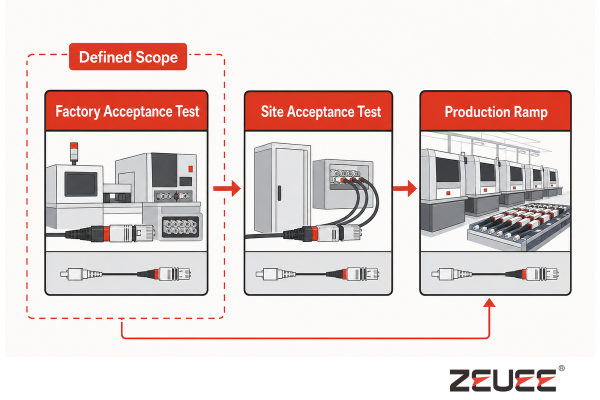
A useful constraint comes from NIST’s conformity decision-rule guidance: acceptance depends on the defined decision rule and measurement uncertainty. A witnessed pass therefore has meaning only inside the agreed method and conditions. Name that boundary in the report before signing it.
Factory Acceptance Testing can confirm that the client has verified the operation of the specified functions and controls at the supplier’s factory, under the agreed conditions. It can demonstrate that a defined connector configuration was loaded to the line, the agreed-upon recipe and tools were used, needed assays were performed, deviations followed the planned sequence, logs were documented, and witnessed outputs were compliant with the agreed-upon frozen acceptance criteria.
That evidence is useful, but boundary is important. An FAT doesn’t necessarily mean that the operating behavior of the installed line will be the same after shipping, connection to the utility and integrating into a network, exposure to different conditions, or change in personnel. These belong to the site acceptance testing, site integration testing, or qualification as relevant to the project.
Finite FAT evidence doesn’t assure sustained process capability. The NIST process-control handbook distinguishes stability from capability. Stability is demonstrated by a sufficient number of observations over time. Capability can’t be assessed until stability is demonstrated. The “sample witnessed” run and a capability study answer different questions.
| Evidence stage | Question it can answer | What it should not be stretched to prove |
|---|---|---|
| FAT | Did the defined factory functions, challenges, methods, reactions, and records meet the agreed acceptance plan? | Installed performance, sustained capability, or unrestricted handling of untested variants |
| SAT / site integration | Does the installed system work with site utilities, networks, upstream/downstream equipment, and local procedures? | Long-run statistical stability |
| Capability study | Is a stable process consistently performing relative to a defined specification? | Every future material, recipe, connector, or maintenance state |
| Ramp release | Are people, materials, maintenance, quality reaction, and output stable enough for the next production stage? | Permanent waiver from change control |
Write the limit into the acceptance record: “Passed FAT for these variants, sample states, methods, software/recipe versions, and witnessed conditions.” That sentence is more defensible than “line validated.”
Which Requirements Must Be Frozen Before FAT?
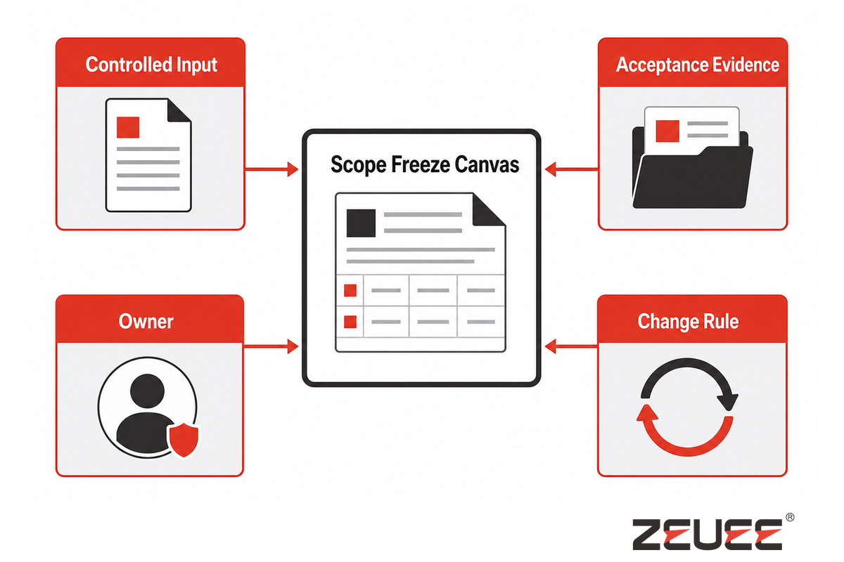
A NASA workmanship example keeps documented preassembly verification, connector-part examination, post-termination inspection, and later testing as separate evidence. It is mission-specific, not a universal factory-line standard, but the separation shows why one signed result cannot silently cover changing inputs or methods.
The witness sign-off date shouldn’t be the first time that the buyer and integrator establish a definition of “good.” Before the test, the buyer and integrator should complete a Scope Freeze Canvas. This document doesn’t have to be detailed, but it must describe for each requirement the controlled input, acceptance evidence, and the owner for each requirement that could affect the outcome.
| Requirement category to freeze | Why it changes acceptance | Expected FAT evidence | Owner |
|---|---|---|---|
| Product, drawing, and revision | A result has no stable meaning if the build definition can move during the test. | Revision check against sample traveler and recipe | Buyer design / configuration owner |
| Connector and optical interface | LC, SC, FC, MPO, and other interfaces are not interchangeable validation scopes. | Approved variant matrix and change-part list | Product and process engineering |
| Fiber and cable construction | Fiber mode, geometry, coating, buffer, strength member, and cable design affect handling and measurement. | Material identity at line entry and record join | Buyer quality and supplier process owner |
| Materials and process instructions | Adhesive system, shelf life, preparation, cure instruction, polish specification, and rework permission define the process envelope. | Approved instruction/version and lot/expiry checks | Process engineering |
| Inspection and optical test methods | The same numerical limit can yield different decisions under different references, wavelengths, cleaning states, or algorithms. | Signed Measurement Agreement Card | Quality / metrology owners |
| Sample and defect set | Nominal good parts alone do not exercise detection or reaction. | Boundary Sample Grid with serialized samples | Buyer and supplier quality |
| Traceability and data ownership | Pass records are weak when they cannot be joined to material, process, inspection, rework, and release state. | Field map, retention rule, export, and retrieval test | Quality and data-system owners |
| Safety and interfaces | Guarding, controlled energy isolation, optical-source exposure, utilities, networks, and equipment handshakes may have separate acceptance duties. | Applicable safety file and interface challenge list | Machine safety and integration owners |
Don’t just freeze connector names. An assertion that a line “supports LC and SC” still leaves definition of cable and fiber, construction, tooling, ferrule and interface, optical reference, packing, labeling, and changeover evidence to be determined. Each Family approved as validated scope should be considered as a defined scope, not as evidence that the line will support any housing, ferrule, material, or cable presented in the future.
Also freeze who can change a requirement and what happens after a change. If a test method, recipe, fixture, software rule, or drawing is compiled after the FAT starts, we record which checks need to be repeated. Otherwise, the team may end up with a clean report for a configuration that no longer exists.
Purchased labels will broaden this scope. A benchtop connector assembly machine, modular connector assembly equipment, and a linked automated assembly production line may involve different tasks. Identify fiber optic components, connectors, and cable assemblies in the real product mix. For example, an LC fiber connector and an SC variant require their own controlled tooling, interfaces, and witnessed changeover evidence. Then describe if epoxy dispense, epoxy cure, polishing, vision inspection, apex offset, optical test, labeling, and packaging are included in the supplied scope. Only then do throughput and acceptance criteria for quality control become comparable.
How Do You Establish Measurement Agreement Before Acceptance?
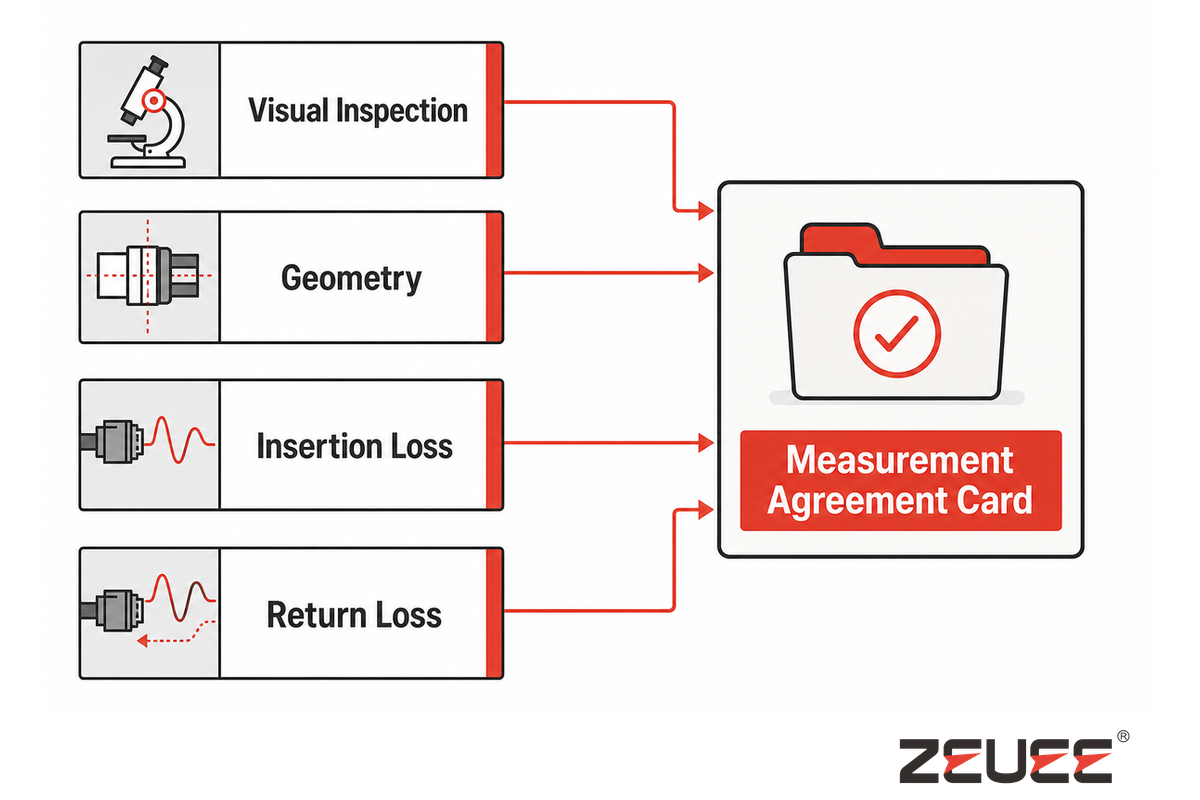
Disputes over measurement are commonly mistaken for a line failure or dismissed as “normal variation.” Correlate both measurement systems before the witness run. Both reactions are premature. Before passing judgment on connectors, buyer and supplier should agree to the same measuring question.
Keep four evidence families separate:
- Visual end-face inspection classifies contamination, scratches, and other observed conditions under a defined inspection rule.
- Interferometric geometry evaluates specified ferrule/end-face geometry parameters using an agreed analysis definition.
- Insertion loss is the measurement of the power that’s lost at the end of the link due to the connection of the fiber, the launch conditions of the fiber, the wavelength of the light, and the reference conditions of the connection.
- The measurement of reflected optical power under specified conditions and in a given state of the connection is return loss.
The scope statement for IEC 61300-3-35:2022 is unusually helpful here. It says visual inspection is additional to, and does not replace, attenuation, return-loss, or end-face-parameter measurement. It also says a connector cannot be rejected solely on a visual-inspection failure; the specified optical performance determines whether the connector may be used. That does not cancel a customer’s cosmetic or workmanship requirement. It prevents a visual rule from being presented as proof of every optical property.
The FOA testing reference explains insertion loss as the power difference measured across a mated connection and discusses known-good references, the relevant fiber and wavelength, launch conditions, and clean reference connectors. Separately, the inspection guidelines distinguish manufacturing inspection for polishing or termination defects from field inspection for cleanliness and damage. Even a dust cap doesn’t assure the end face is clean.
Measurement Agreement Card
For each measurement, provide the instrument and version of software; applicable method and version; reference artifact or cord; fiber and wavelength; launch, mating, cleaning, and environmental conditions; uncertainty; correlation-sample result; numerical units and rounding; limit; guard band or other borderline decision rule; retest permission; retained raw record; and the person who resolves a dispute.
The calibration sticker isn’t the entire answer. NIST’s metrological traceability guidance states that traceability alone doesn’t ensure fitness for purpose and that measurement uncertainty must be considered. NIST’s work on conformity decision rules goes one step further: uncertainty and the decision rule affect false acceptance and false rejection. For a result close to a limit, “the screen says pass” isn’t a complete contract.
Run correlation samples prior to the official pass/fail sequence. Use the same serialized connectors on both systems, ensure they’ve the same cleaning and mating history, compare the outputs, and agree upon a response if the systems disagree. A NIST interlaboratory comparison of end-face geometry measurements reported systematic and random differences among the approaches used for measurement. The point isn’t to borrow their old numbers. The point is to make the measurement agreement visible.
Which Samples Should an FAT Challenge?
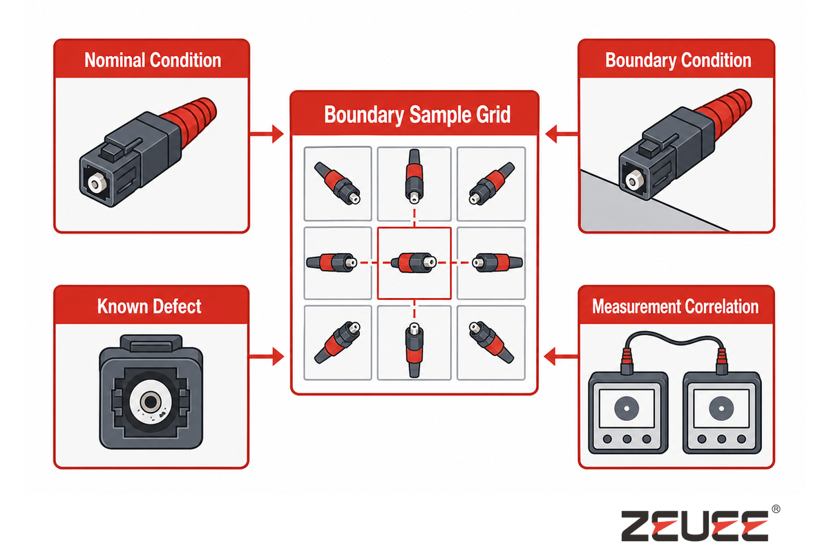
NIST’s conformity-assessment work is also why a near-limit result needs a written rule before the run. Boundary samples reveal how that rule behaves; they do not authorize the team to invent a limit after seeing the data. Write the expected outcome before testing.
If all samples are clean, nominal, and preselected and if they come from one material lot, the FAT mostly verifies that the easiest case can be run. Create a Boundary Sample Grid that spans the engineering range and includes the detection/reaction scenarios that the team needs to observe.
| Grid dimension | Example challenge | What to witness |
|---|---|---|
| Connector/interface family | Each contracted family, not a verbal “similar” variant | Correct tooling, recipe, inspection profile, test method, and record identity |
| Fiber/cable construction | Contracted single-mode/multimode or cable builds | Material recognition, handling scope, correct test conditions |
| Material state | Different approved lot; near defined internal boundary where safe | Lot/expiry checks and reaction to unidentified or invalid material |
| Dimensional condition | Nominal and agreed boundary components | Feed, fixture, detection, disposition, and retained evidence |
| End-face condition | Controlled clean, contaminated, and documented defect images/samples | Classification consistency and correct reaction |
| Rework state | Allowed and prohibited rework examples | Authorization, route, history preservation, and retest rule |
| Label/pack variant | Each contracted label or packaging rule | Correct identity and prevention of mixed release |
| Measurement-system state | Serialized correlation samples checked on buyer and supplier systems | Agreed reference conditions, uncertainty treatment, and dispute response |
A safe and serialized, photographed, approved, and isolated known-defect set should be used to challenge detection and reaction. It shouldn’t be used to deliberately create defects that affect the production tooling or make the subsequent result invalid.
The engineering grid, in and of itself, isn’t an acceptance sampling plan. If the contract uses statistical sampling, separately define the lot, sample independence, representativeness, sample size, acceptance number, and producer/purchaser risk. More random samples can’t be used to replace missing boundary cases. Boundary sets can’t substitute for valid statistical evidence when a statistical acceptance requirement applies. The two approaches aren’t the same and can coexist.
Useful recording rule: every challenge sample needs an expected state before it reaches the line. If the expected result is written after the system responds, the test can be unconsciously graded to fit the outcome.
What Must Be Proven Across the Process Without Repeating the Station List?
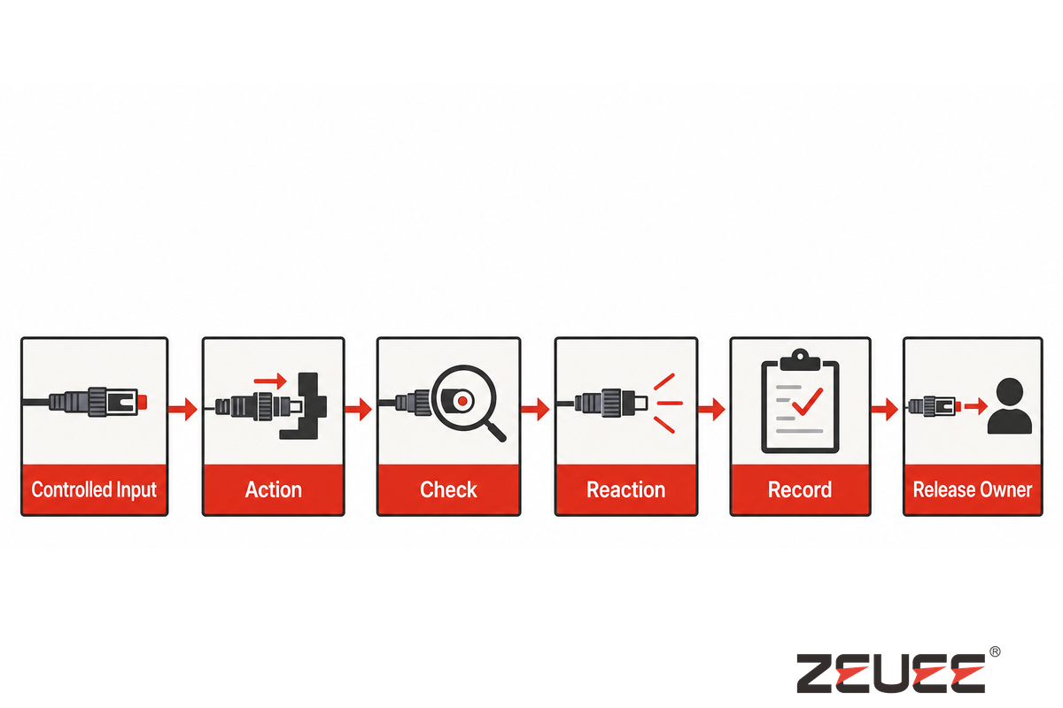
Instead of going through each step again, evaluate each requirement family with the same evidence chain: This links the boundary samples from the previous section to process controls, reactions, records, and release ownership without pretending that a station list is proof.
controlled input → action or transformation → check/measurement → reaction → record → release owner
This structure demonstrates the deficiency of a station list. While a materials scanner may determine an approved lot, the FAT must demonstrate what happens when the lot is unknown, expired, or assigned to the incorrect product. An inspection station may detect an end-face condition; however, the test must determine if the connector is placed on hold, reviewed, authorized for rework, or scrapped. Although a database may store an image, the team must demonstrate that the image is joined to the correct connector and the release decision.
A mission-specific NASA workmanship document provides an instructive example of evidence separation: it treats documented preassembly verification, examination of connector parts, post-termination inspection, and later testing as separate activities. It isn’t a universal factory-line standard, and this article doesn’t use it that way. The useful idea is that an upstream check, post-process inspection, and functional test don’t erase one another.
Apply the chain to these requirement families:
- Configuration: product revision, connector family, approved material, tooling, recipe, and software rule.
- Process evidence: actual versus approved parameters, timing, fixture identity, and maintenance state where relevant.
- Inspection: image/sample identity, profile and revision, result, reviewer path, and disposition.
- Optical test: method, references, conditions, raw result, decision rule, and record link.
- Exception control: reason for hold, affected population, authority, rework route, retest, and final status.
- Release: who’s authorized to release what, against which records, and how mixed or incomplete units are held.
This part of FAT is satisfied when the team can trace each requirement from input to final disposition without having to memorize anything. If an operator has to say, “We usually know which batch that was,” then the control may work socially, but there’s no documented evidence.
How Should Changeover Be Challenged?
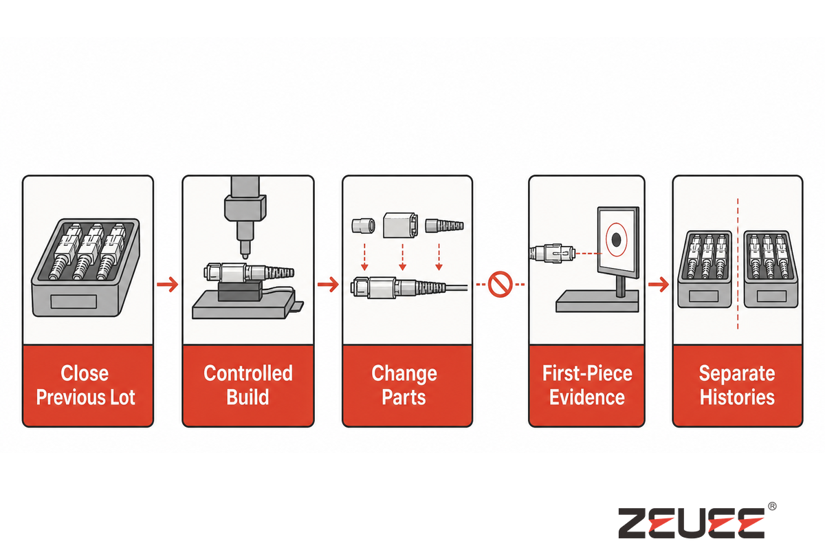
The evidence-separation principle in this NASA workmanship document is useful here: upstream verification, post-process inspection, and later testing remain distinct records. During changeover, the new build needs its own joined evidence rather than inheriting the previous lot’s proof. Retain both result sets.
Changing the name of the recipe on the HMI alone doesn’t constitute a changeover test. Changing the connector family may involve new tooling, material, inspection, optical reference, label, data fields, and first piece approval. Therefore, the FAT should witness a complete variant transition and not just the selection screen.
- End the previous lot under control. Total the units in process, resolve any remaining materials, and complete the record for the lot.
- Select the new controlled build. Load the approved product/drawing revision and demonstrate that unauthorized combinations are blocked.
- Verify physical change parts. Record fixture, nest, guide, tool, and reference changes and don’t rely on appearance.
- Verify material and method. Confirm the new fiber/cable, consumable, process instruction, inspection profile, optical setup, label, and packing rule.
- Challenge a wrong carryover. Safely, present a prior recipe, wrong component, or stale identifier and witness the intended block.
- Run first-piece evidence. Complete the agreed inspection/test set and obtain the named approval before normal output is released.
- Retrieve both histories. Prove the last unit of the old build and first accepted unit of the new build can’t be confused.
Record time only after defining start and finish conditions. “Five-minute changeover” is meaningless if one team starts timing after cleaning and setup while another starts at the last good unit and stops at the first approved unit. If changeover time is contractual, freeze the boundary, crew, material readiness, approval steps.
Most importantly, don’t infer unlimited flexibility from one witnessed transition. The FAT supports the variants and transitions actually included in its scope. Later changes to the ferrule, housing, cable construction, adhesive, inspection algorithm, or optical method may require change assessment and partial requalification.
How Do You Test Fault Reaction, Containment, and Recovery?
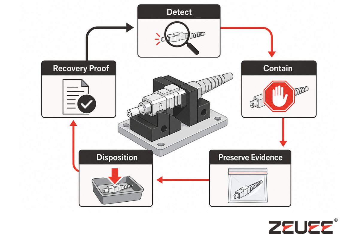
The linked NASA workmanship example treats examination, post-termination inspection, and later testing as separate controls that must remain visible in a recovery record. The same evidence discipline applies after a fault: detecting a condition cannot substitute for disposition, restored process state, and retest evidence.
An alarm proves that something was detected. The FAT must exercise the complete controlled response chain. It doesn’t prove that affected units were contained, their state was preserved, the cause was reviewed, recovery was controlled, or release authority was respected.
Use a Stop-and-Contain Drill for recognized faults with the following examples: unidentified material, invalid combination of recipe and tooling, missing image or inspection reject, abnormal optical result, lost data connection, interrupted processing or a similar case where the unit’s status is uncertain. Do not introduce an unsafe condition; use only an approved simulation method.
- Introduce or simulate the recognized fault and record its identity.
- Witness stop, block, or diversion at the correct boundary.
- Identify every potentially affected unit, including work in process.
- Preserve recipe, measurement, and event state needed for investigation.
- Apply the named review and disposition path: rework, scrap, return, concession, or other authorized decision.
- Retest only with the approved rule, leaving the original failure in place
- Restore tooling, recipe, references, cleanliness, and data connection.
- Run a Recovery Proof Run and release it through the named authority.
A plan of continual cleaning, or continual testing of a connector, isn’t a valid fault response. This can mask a damaged surface, measurement instability, a contaminated reference, or a process shift. The record must be maintained, and should include the original result, each permitted intervention, the final disposition, and the reason the unit is, or isn’t, releasable.
Maintain a distinction of safety acceptance for machines. Guarding, interlocks, controlled energy isolation, maintenance access, emergency functions, and optical-source exposure should be tested for the project’s risk assessment and applicable standard scope. General alarm-recovery demonstrations aren’t substitutes for those functions. This guide doesn’t define their specific criteria.
Can the Team Retrieve a Connector’s Genealogy?
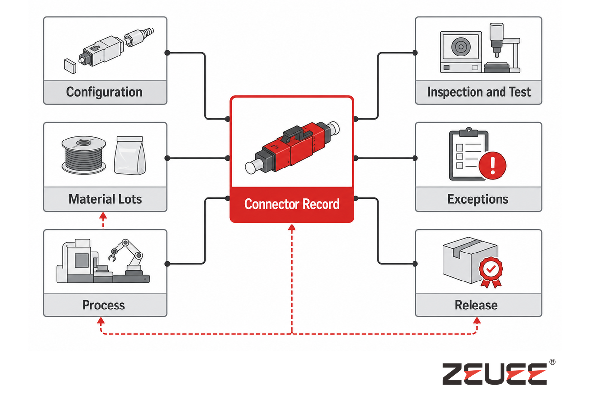
The separate verification, inspection, and test records in this NASA workmanship document illustrate the join that genealogy must preserve. The example is mission-specific; here it supports the record-linkage principle, not a universal record format. Keep the join bidirectional and exportable.
Traceability is helpful when it provides an answer to a containment question. A serial number in a database is simply the starting point. A user should be able to select one connector and retrieve all trace data related to the connector to allow a determination if the connector is from a suspect population and whether it was legitimately released.
Thirty-Minute Genealogy Retrieval Test
Select an accepted connector, a reworked connector, and a held or rejected connector without informing the operator which records will be requested. Allow the team 30 minutes to develop an integrated evidence pack. This format is a ZEUEE design test, not an industry standard or promised line performance.
The packet should connect, where applicable:
- product, drawing, and route revision;
- connector, fiber/cable, adhesive/consumable, and other controlled material lots;
- tooling, fixturing, recipe, inspection profile, software, and measuring method;
- the actual process and state records called for by the control plan;
- where applicable, end-face image/classification, geometry result, insertion loss result, and return loss result;
- alarms, holds, rework, retests, deviations, and original results;
- operator or system identity, timestamps, and release authority;
- final label/pack identity and shipment status where in scope.
Then reverse the question. Consider a material lot, recipe, failed reference, or inspection-profile change and determine the affected connector population. Forward genealogy without reverse containment may provide a lovely unit history and a cohesive record, but it leaves the quality team without defined risks.
confirm retention, access, export format, clock synchronization, backup and backup, and ownership. Also test the behavior when a network or database isn’t available. Does the line become impenetrable and untraceable? Whatever the selected design, the FAT should confirm the agreed to rule and its recovery path.
What Are the Nine FAT Acceptance Checks?
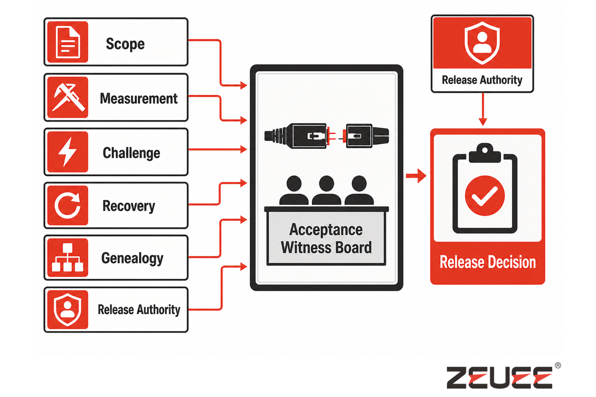
The board also retains the measurement decision rule because NIST’s conformity guidance shows that uncertainty and the chosen rule affect false-acceptance and false-rejection risk. A check mark without that context is not complete acceptance evidence. Every row therefore needs its evidence link and owner.
The Acceptance Witness Board below places the work onto a single decision surface. This is a planning instrument, not a published standard. Each check must have a scope, witness, result, evidence link, open item, and named release authority for every row.
1. Scope freeze
Product, revision, connector/fiber/cable boundary, materials, methods, variants, interfaces, safety scope, and responsibilities are approved before the run.
2. Measurement agreement
Inspection, geometry, insertion-loss, and return-loss setups are correlated. Uncertainty, rounding, borderline decision, retest, and dispute rules are recorded.
3. Nominal build
The line makes the agreed nominal configuration using controlled materials, tooling, recipe, and records. This proves the defined demonstration, not every future condition.
4. Boundary/defect challenge
Serialized boundary and known-defect samples exercise detection and reaction. Expected results were documented before the line responded.
5. Control-evidence chain
For every required family, the team can follow controlled input through action, check, reaction, record, and release owner.
6. Changeover challenge
A contracted variant transition covers lot closure, recipe/tooling/material/profile changes, first-piece approval, wrong-carryover block, and history separation.
7. Fault and recovery
Agreed faults trigger correct stop/diversion, bounded containment, preserved evidence, authorized disposition, controlled restoration, and recovery proof.
8. Genealogy retrieval
Accepted, reworked, and held/rejected units produce joined evidence packets, while a reverse query identifies affected populations.
9. Acceptance boundary
The report states what was witnessed, what passed, open items, concessions, repeat-test triggers, and what remains for site testing, capability, or ramp release.
One red check doesn’t always generate the same commercial reaction. Describe the problem. A missing document may have to be supplied with supporting evidence. Acceptance may be blocked by a failed safety function or by containment not being met. A condition outside the frozen scope may become an open change and not a failed requirement. These pathways should be documented in the contract before the FAT and shouldn’t be addressed during the last minutes of contract negotiations.
A green board doesn’t mean more conclusion. Your report should include sample identities, variant transitions, faults, references, environmental/utility conditions, versions, and witnesses. Indicate the presence of evidence or reference proofs by maintaining raw data or strong links instead of a summary from the slide deck.
ZEUEE claims to have started in 2005 and offers industrial automation engineering, and readers can check on the company’s engineering background. This is first-party context and not independent evidence that a given line will satisfy a customer’s requirement. The evidence for a given project should remain in the agreed-upon tests and records.
What Should a 2026 Optical Connector Line Brief Require?
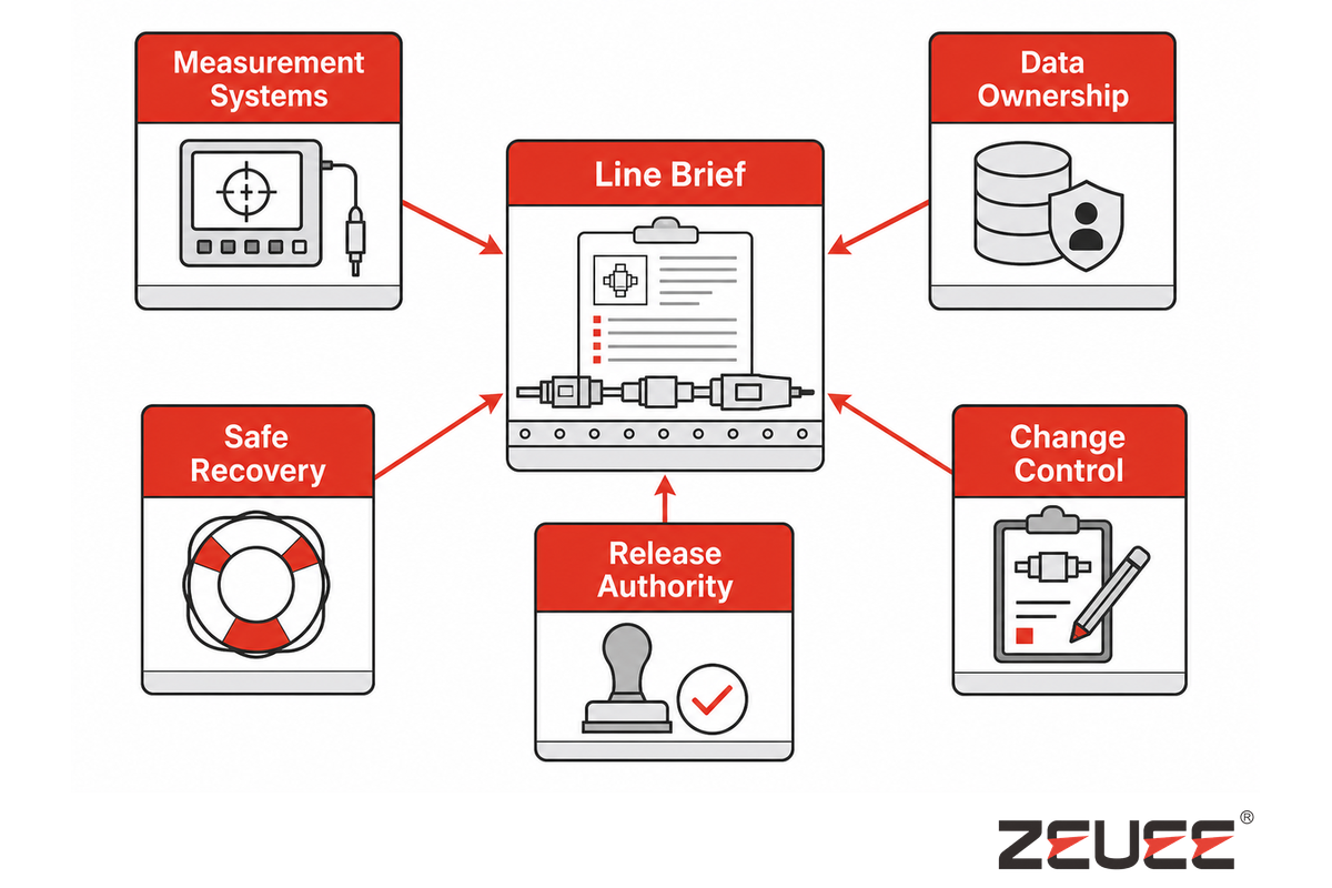
The current IEC 61300-3-35 edition is a useful model for scope discipline because it explicitly separates visual inspection from attenuation, return-loss, and end-face-parameter measurement. A modern line brief should make those method boundaries visible before automation or data architecture is selected.
An up-to-date brief should be more specific than “automate LC/SC assembly at the required output”. The reviewed evidence doesn’t support a clear, defensible emerging market signal that would assist the buying decision, so this guide doesn’t add a market-growth section. The most relevant dated evidence is the current standard scope and the requirement to connect process, inspection, test, and traceability data; ZEUEE’s production line automation guide provides broader integration context.
At minimum, the one-page brief should name:
- product, connector, ferrule/interface, fiber/cable, material, and revision boundaries;
- approved process instructions and rework permissions;
- applicable drawings, customer rules, and exact standard editions, including the limited visual-inspection scope of IEC 61300-3-35:2022 where applicable;
- inspection, geometry, IL, and RL methods, references, uncertainty, decision rule, data retention, and correlation;
- Boundary Sample Grid plus any separate statistical acceptance-sampling plan;
- contracted changeovers and first-piece release;
- fault, hold, containment, rework, retest, recovery, and release paths;
- genealogy, reverse containment, access, export, retention, and failure behavior;
- machine-safety, utilities, network/data interfaces, access control, backup, and change control;
- FAT, factory integration, SAT/site integration, capability, and ramp-release ownership;
- unresolved assumptions, exclusions, concessions, and repeat-test triggers.
An application for a 2025 patent for an optical fiber polishing arm assembly exemplifies that fixture geometry, locking, and durability remain viable areas of active invention. Adoption or performance in production isn’t described. In the patent application, the fixture identity along with known maintenance status and parameters that are under user control must be included to justify acceptance.
After the scope is set, review ZEUEE’s optical connector assembly line solution for configuration and commercial considerations. In line with the solution for layout and placement of stations, the products supported, promise of performance, price, and proposal will be along that solution path and not in this guide for informational acceptance.
Turn Your Requirements Into a Witnessable FAT Plan
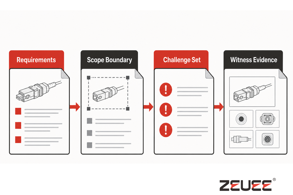
Start with the method and decision rule, not a generic pass label. NIST’s conformity-assessment guidance provides the reason: measurement uncertainty and the chosen rule change the risk attached to the final decision.
Bring drawings of connector variants and supporting material, test methods, specifications of the anticipated interface, and your acceptance criteria. A generic RFQ creates an acceptance risk when the buyer and supplier reach the factory with different definitions of a passing connector. ZEUEE will use this information to develop a line concept and the supporting evidence for your project.
FAQ: Optical Connector Assembly Line FAT
Why is automating fiber optic connector assembly so difficult?
The work comprises components fabricated from delicate materials, assemblies involving tight mechanical and optical relationships, surfaces sensitive to contamination, materials and time control, several families of measurements, and product variability. Automation must be more sophisticated than simply assembly. It must preserve the identity of fibers and connectors, apply the controlled product path, discern contamination from surface damage, use the intended inspection and optical techniques, respond appropriately to exceptions, and maintain evidence associated with the released product. Small changes in input can have significant effects on handling, tooling, materials, measurement frameworks, and acceptable rework.
As the product boundary or acceptance criterion becomes fuzzy, so too does the difficulty. In that case, no machine can automate decisions the project team hasn’t yet made. The first step isn’t the selection of a faster robot. It’s freezing product variants, process instructions, acceptance criteria, exception routes, data fields, and release authority so automation has a well-defined task to perform and a way to demonstrate such performance.
What end-face quality can an optical connector assembly line hold?
Without a defined connector, finish, inspection method, geometry requirement, optical requirement, sampling or test rule, operating envelope, and corresponding standards, a responsible universal answer is not possible. Freeze the applicable drawing/customer criteria and the exact standard edition, and confirm measurement agreement and run the specified samples. IEC 61300-3-35:2022 refers to visual inspection, but its public declaration states that inspection should not replace attenuation, return loss, or end-face parameter measurement. Ask a supplier to provide evidence associated with your product and procedure, rather than an unrelated “IEC compliant” statement or a best-case scenario image.
Will one line handle different connector configurations?
Several contracted variants may take up one line, but each variant generates a validation scope. Define connector/interface, ferrule, fiber and cable construction, materials, tooling, recipe, inspection profile, optical references, label/pack requirements, and data fields. The FAT should verify the agreed changeovers and a wrong-carryover challenge, while also preserving first-piece approval and variant history.
A passed LC-to-SC transition doesn’t guarantee that the other housing, cable, adhesive and polishing requirements will be successful. Later additions should go through documented change assessment. The result can be a paper review, an engineering run, a targeted FAT, or a broader requalification, depending on what was changed and what acceptance evidence is Impacted by the change.
What is the difference between FAT and SAT for an assembly line?
FAT is performed at the supplier’s factory to verify the agreed functions, samples, measurements, reactions, and records before shipment. SAT is performed post-installation to verify the system in its real world context, including utilities, networks, local interfaces, upstream/downstream equipment and site activities and procedures. Projects can define factory or site integration tests. Neither of the tests automatically provides long-run capability, which requires stability and production evidence over time.
What causes two optical test setups to disagree?
Potential causes include reference cords/connectors, history of mating, cleanliness, fiber type, wavelength, launch condition, adapters, instrument settings, software algorithms, calibration/traceability, environmental conditions, rounding, and treatment of uncertainty near a limit. Compare the same serialized correlation samples while keeping them in the same condition. Then agree on the method, uncertainty, decision rule, retest permission and dispute owner prior to the collection of official acceptance data.
Does every optical connector need insertion-loss and return-loss testing?
Not entirely governed by one rule. Overview of product specifications, customer agreements, applicable standards, and risk and control plans shall guide the key elements of inspection and test coverage. Full optical tests may be required for some projects, sampling (or qualification) of tests in some cases may be justified. This guide won’t be able to define this requirement without the context of the product and contract. However, this guide can impose clarity: indicate which attributes are inspected and tested, state which units are inspected or tested, provide the method used to conduct the inspection, document which references are used, and include the decision rule. Optical performance shouldn’t be shown to be fulfilled by stating that visual inspection was performed.
References & Sources
- IEC 61300-3-35:2022 official product scope and lifecycle page.
- The Fiber Optic Association: Fiber Optic Testing.
- The Fiber Optic Association: Optical Inspection of Connectors with Microscopes.
- NIST: Optical Fiber Connectors, an Interlaboratory Comparison of Endface Geometry Measurements.
- NIST: Metrological Traceability.
- NIST: Assessment of Conformity, Decision Rules and Risk Analysis.
- NIST/SEMATECH e-Handbook: Process Capability.
- NASA Workmanship Requirements for mission-specific electronic hardware, fiber-optic assembly section.
- FOA Installation Standard 2025 V1. FOA Installation Standard 2025 V1 , retained for documentation and responsibility context; its scope is installed cable plants rather than production-line certification.
- Cisco: Inspection and Cleaning Procedures for Fiber-Optic Connections. Cisco: Used as an operational background rather than a manufacturing standard.
- ASSEMBLY Magazine: Assembling Fiber Optics. Trade-journal background.
- US20250100106A1: Optical Fiber Polishing Arm Assembly, cited only as an invention record.
The ZEUEE technical team may review this guide for a specific project. The specific technical requirements, safety obligations, sampling plans, and acceptance criteria must be addressed for the connector, site, contract, and jurisdiction.
WHY WE WRITE THIS
About ZEUEE Engineering Insights
ZEUEE shares technical guides based on real automation project experience. Since 2005, we have designed and manufactured non-standard automation equipment for connector assembly, wire harness production, robotic lines, vision inspection, and smart factory upgrades.
Founded in 2005
20,000 m² production base
120+ specialists
150+ R&D patents
ISO9001:2015 certified