Get in touch with Zeyu lntelligent Industrial Company

Automated Screwdriving Systems: Specify and Verify the Assembly

![Automated Screwdriving: Torque & Cycle Time [Guide]](https://zeueeauto.com/wp-content/uploads/2026/10/automated-screwdriving-featured.png)
Automated screwdriving employs a controlled screwdriver, screw supply and positioning equipment to fasten parts in a programmed sequence. An acceptable specification connects that sequence to a finished assembly: the joint must meet its acceptance limits, the part must leave within the specified cycle time, and its results must be traceable.
A fast running demonstration may cover up a slow feeder refill, an awkward fixture, or an absent result record. Before requesting a price on a machine, identify which screws the station handles, and what part specifications are considered acceptable. The worksheets that follow support comparison of robotic screwdriving with other assembly processes under the same test conditions.
What Automated Screwdriving Actually Includes
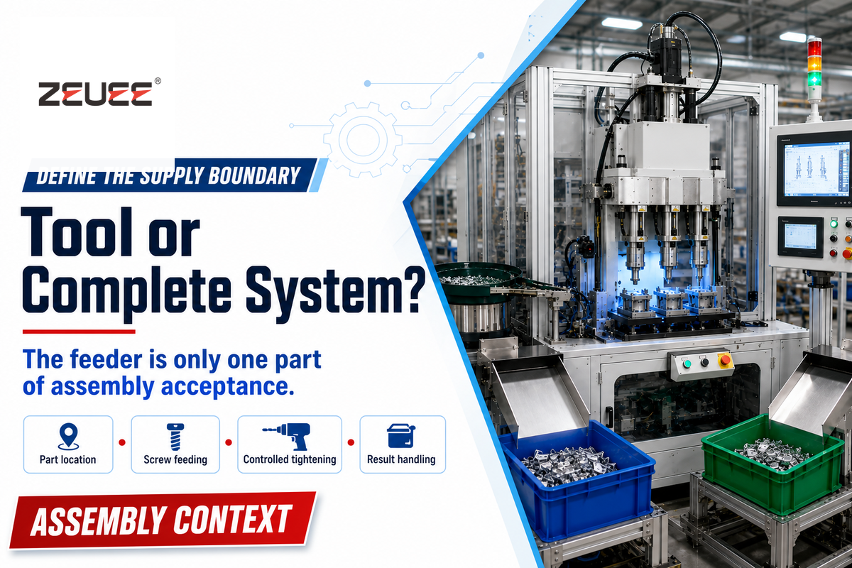
An automated screwdriving system integrates screw feeding, part location, tool movement, tightening, and result handling. An automatic screwdriver alone doesn’t integrate all those functions. Buyers should spell out the complete assembly sequence, including the response to a failed joint, to compare an assisted workstation to a robot cell or dedicated machine.
The OPC Foundation tightening model describes several arrangements including handheld tools and fixtured spindles, as well as a spindle with a feeder mounted on a robot. The model’s system boundary doesn’t include the robot. This distinction is relevant when one supplier quotes fastening hardware and another quotes complete automated assembly equipment.
What is an automatic screw feeding machine?
An automatic screw feeding machine separates screws from a bulk supply and presents or transfers them to a screwdriver. Feeding systems may provide a pickup point or move a compatible screw through a feed tube. The feeder doesn’t, by itself, establish the joint’s final torque, seating, or assembly acceptance.
One common mistake in purchasing is to consider the process description of “feed and drive” as complete. Who supplies the nest, part clamp and reject handling? For a proposed four-screw assembly, the quote should depict four required joint results and one part release. Process reliability depends on this entire process; a screw counter is only one input to the part release decision.
Specify the Screw, Joint and Feeding Route
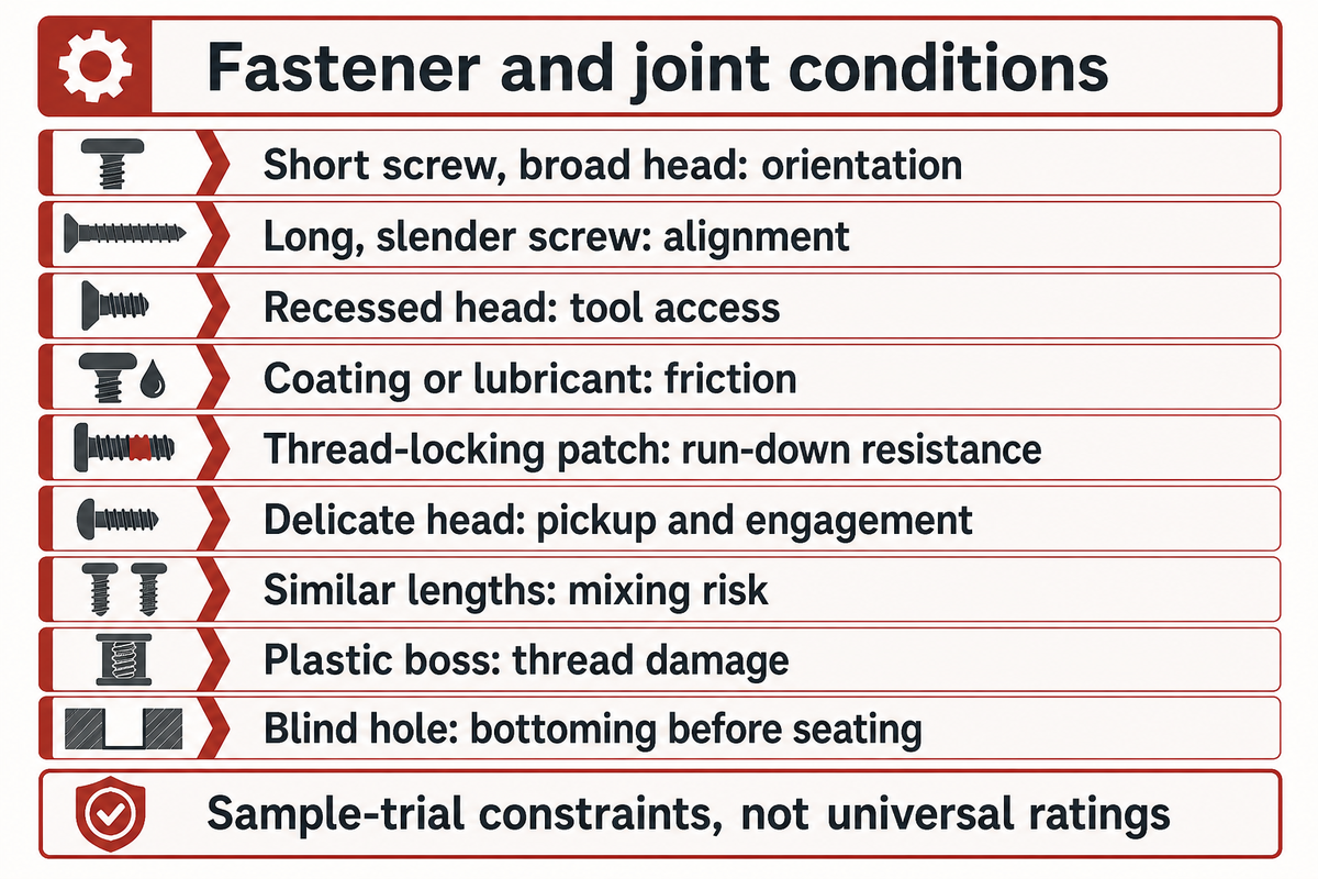
Screw geometry and joint access determine the feeding route, and the brand of robot becomes secondary. Provide actual fasteners, mating parts, and drawings. Head shape, length, coatings, and pick-up access can define how a screw is fed and how the bit engages. These features can also affect whether a screwdriver can reach the correct depth without contacting surrounding features.
Use the condition matrix to identify the trials needed for different products. The entries address common issues in feeding and joint access, NOT universal feeder ratings. A vibratory bowl, hopper, escapement and pickup module each need a defined screw family; a software recipe can’t change their physical clearances. Compare these constraints with the planned product mix of the assembly line.
| Condition | Likely constraint | Sample evidence to request |
|---|---|---|
| Short screw with a broad head | Orientation or feed-tube stability | Continuous feeding with the actual geometry |
| Long, slender screw | Transfer and insertion alignment | Pickup-to-hole sequence without bending |
| Recessed screw head | Nosepiece and bit access | Tool envelope against the part drawing |
| Coated or lubricated screw | Friction and handling behavior | Production-condition torque trials |
| Pre-applied thread-locking patch | Run-down resistance | Joint-specific torque and angle signature |
| Small or delicate head | Pickup seal and drive engagement | Retention and head-damage inspection |
| Two similar screw lengths | Mixing during refill or changeover | Wrong-fastener challenge and line clearance |
| Plastic boss | Thread formation and damage limits | Validated seating and stripping margins |
| Blind threaded hole | Bottoming before seating | Depth, engagement and head-seat inspection |
Consider an illustrative example of electronics housing with M3 × 8 mm screws and an example of electronics housing with M3 × 10 mm screws. The recess is the same for both examples, so using the correct bit doesn’t guarantee the correct length has been used in the joint. A mixed refill could result in the shorter screw not engaging fully or the longer screw bottoming in a blind hole. Give the supplier both variants and agree how changeover clears the previous fasteners, using a dedicated feed path, verified loading or suitable inspection if needed. The choice would be verified in the sample trial, with its added time included in the quote.
For a difference of 2 mm between the two lengths of screws, selection of recipe alone isn’t sufficient to establish physical identity. Joint verification and prevention of mixing of different lengths should be treated as separate requirements. Evidence for both lengths including the first assembly after changeover should be presented by the supplier to a buyer verifying feeding systems before accepting a common feeder.
Set Torque Limits Against the Actual Joint
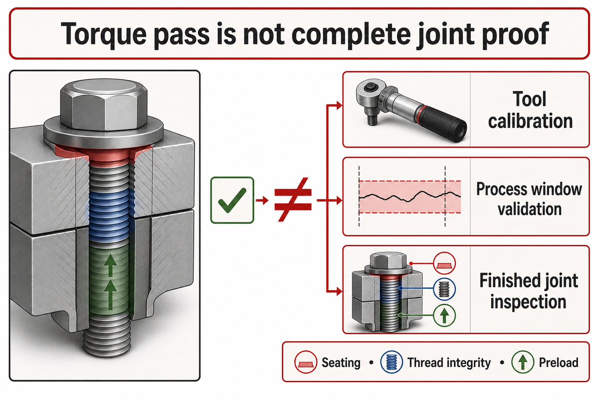
Torque limit settings for a joint are defined by joint design and a validated tightening process. Torque is an indirect measure of clamping force because friction consumes part of the applied effort. Therefore, a torque pass doesn’t guarantee a good joint. A joint may still be loose, have damaged threads, or have insufficient preload. Monitoring of joints is dependent on the failure consequences and the joint design.
NASA’s torque-tension study looks at threaded inserts and lubrication. The public abstract doesn’t establish a friction factor for every assembly. Obtain the design owner’s torque spec, screw condition and test method, and qualify the spindle and controller on production-representative parts.
ISO 5393:2017 concerns laboratory performance testing of continuous-action powered assembly tools. Its public scope includes 0.5–2,000 N·m, with stated provisions for modified methods outside that range; impact and impulse tools are excluded. That broad scope is not a recommended torque range for a small electronics screw.
“the measurement of torque repeatability (scatter)”
A common mistake is requesting a tight tolerance on tool accuracy while not defining the joint condition. Tool calibration, process window validation, and finished joint inspection are separate activities. A hypothetical 1.2 N·m target, for instance, still requires justified limits. A generic percentage copied from a different tool doesn’t justify a limit. A green indicator should report the acceptance decision, not imply that all possible joint defects were tested.
On a joint specified at 1.2 N·m, the design owner must establish acceptable tightening conditions and the method for verifying the joint. A controller reaching 1.2 N·m supplies a process measurement. Seating, thread integrity and any required service-life preload qualification remain distinct acceptance questions.
Choose Robot-Mounted, Fixed or Assisted Screwdriving
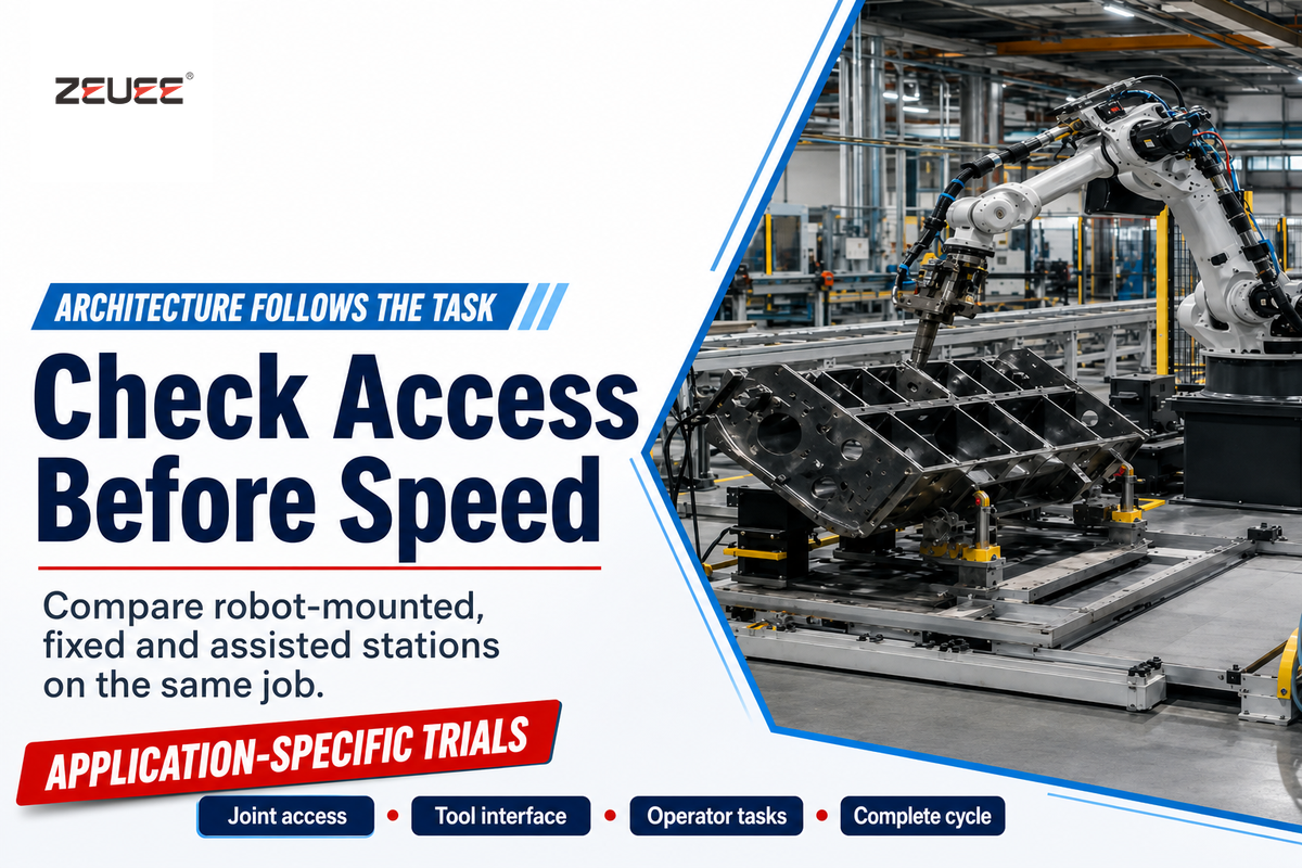
Choose the station architecture based around access, changes to the product, and the kind of work given to the operator. A robot arm can reposition a single spindle between joints, while fixtured screwdriving can use dedicated positions or multiple spindles. An assisted handheld system can retain manual part handling while adding controlled tightening and error prevention to a workstation.
None of the aforementioned architectures guarantee the shortest cycle time. In a 2023 tile-cutter assembly study, the cobot mainly moved and held parts, and people retained screw positioning and joining functions. Reported ergonomic and quality benefits concerned that allocation of work. They weren’t a test of three types of screwdriving machines.
A 2024 collaborative assembly benchmark reported lower workload alongside longer assembly time as compared to manual processes. Treat throughput and ergonomic benefits as separate trial results. A collaborative label doesn’t confirm that a complete screwdriving cell can function without application specific safeguards.
Does this screwdriver attach to the SCARA robot?
A screwdriver can attach to a SCARA robot when the mechanical interface, payload and reaction loads, and controls are compatible. Verify the flange, adapter, tool mass and center of gravity against the limits of the robot. The tool must access each joint without interference from the feeder tube, cables, gripper or part fixture.
Refer to the complete end-of-arm tooling drawing, called EOAT, rather than the photograph of a flange. The working radius and the approach direction must be compatible with the joint. Check how the tooling plate locates the spindle and how the fixture will secure the part. A six-axis robot may provide angled access. A SCARA design may be compatible with joints approached along a common direction. Evaluate either within the robot integration scope, which includes the servicing of the tool and collision clearance.
Calculate Cycle Time for the Whole Assembly
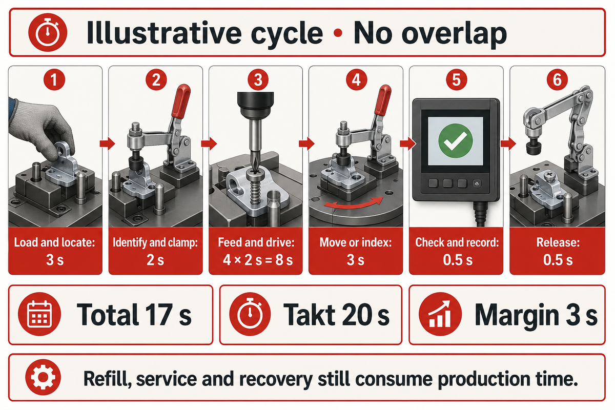
Assembly cycle time covers the time from the agreed start condition to the release of the completed part. It includes loading, identification, clamping, screw delivery, movement, tightening, and result handling. Overlapping operations can shorten the cycle time when demonstrated timing supports the overlap, but a spindle figure alone cannot establish production-line throughput.
6-Stage Accepted-Assembly Clock
The 6-Stage Accepted-Assembly Clock is a worksheet for recording the complete cycle and any demonstrated and verified overlapping.
| Stage | Example time | What the trial should show |
|---|---|---|
| Load and locate | 3 s | Part fully located in the nest |
| Identify and clamp | 2 s | Correct variant and clamp confirmation |
| Feed and drive four joints | 4 × 2 s = 8 s | Each feed-and-drive sequence completed |
| Move or index between positions | 3 s | All additional travel included |
| Check and record | 0.5 s | Required results linked to the part |
| Release the assembly | 0.5 s | Part ready for the next operation |
The example totals 3 + 2 + 8 + 3 + 0.5 + 0.5 = 17 s per assembly. With an illustrative 20 s takt, this provides only 3 s of margin. It doesn’t establish sustained output. A hopper refill, bit change or recovery stop consumes the remaining available production time outside the ideal sequence. The supplier can’t quote the same robot travel within the 2 s joint interval and 3 s movement allowance. Agree on the limits of each interval and mark them on a trial video. If the supplier wishes to drive two screws together, remeasure the sequence; loading and releasing don’t automatically halve.
Have the observed bottleneck brought to the production line timing review. Record sustained runs and downtime separately, so an average doesn’t mask repeated feeder stops. When a pallet carries the assembly, record its release and indexing. NIST’s assembly benchmarking work uses repeatable tasks and controlled factors; buyer and supplier must agree on the repetitions and statistical acceptance method appropriate to the work.
A 17 s nominal sequence against a 20 s takt allows only 3 s of margin before losses occur. Production acceptance should detail the duration, the product mix, and the treatment of interruptions. Increasing screwdriver speed won’t increase production when locating, indexing, or downstream release remains the limiting step.
Prove Rejects and Traceability Before Acceptance
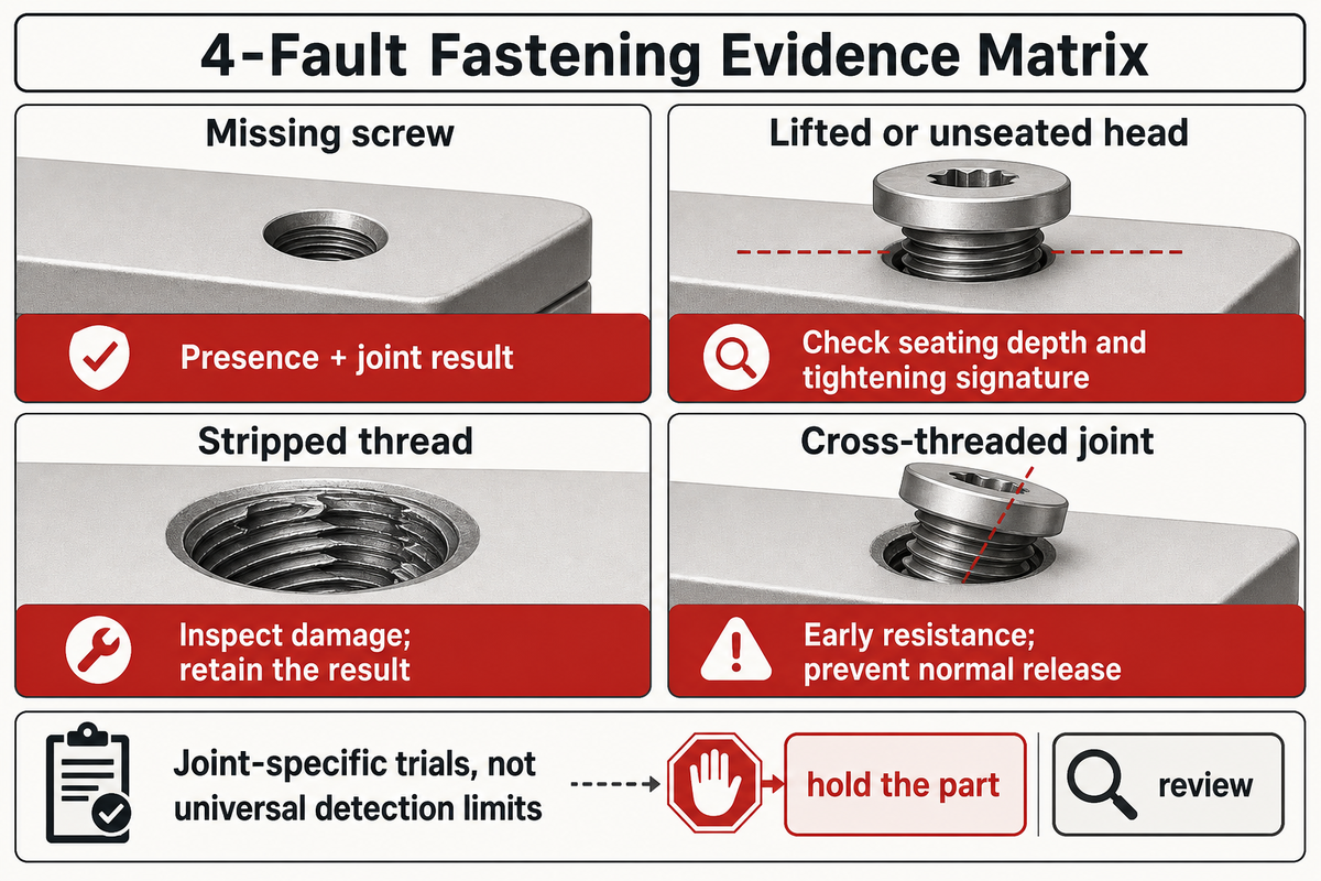
Acceptance testing should evaluate functionality of good joints, challenged faults and a station’s release response. Torque, angle, insertion depth or vision can serve as inputs, but no single signal can prove all defects are detectable. Agree on fault samples and recording rules with quality engineering, and verify that failed/incomplete results prevent an unintended accepted-part release.
“The goal of error-proofing is to both prevent mistakes and catch them.”
4-Fault Fastening Evidence Matrix
The 4-Fault Fastening Evidence Matrix is a challenge worksheet example; it doesn’t specify universal detection limits.
| Fault | Evidence to examine | Limit to test | Required recorded response |
|---|---|---|---|
| Missing screw | Presence, cycle count and joint result | A commanded cycle is not proof of insertion | Identify the missing joint and hold the part |
| Lifted or unseated head | Seating depth and tightening signature | Bottoming may produce torque without seating | Record the failed condition and disposition |
| Stripped thread | Torque-angle behavior and joint inspection | Damage depends on material and engagement | Retain the result and reject or route for review |
| Cross-threaded joint | Early resistance, angle and physical inspection | High resistance can resemble a tight joint | Flag the joint and prevent normal release |
Traceability also needs a data challenge. Break the agreed result path under controlled test conditions and observe what happens to part identity and release. The base specification for the OPC joining system includes result structures and identifiers, but fields such as associated entities and traces are optional. An asserted interface therefore needs an actual field list and sample export.
Request part ID, joint position, recipe revision, result status, and agreed measurements. Determine retention and rework association with the plant’s quality system. Vision inspection may be used for checking presence and height of head; finished-assembly testing may be used for answering other product questions. Clarify responsibilities.
Four fault challenges cover four pre-chosen conditions and don’t assess escape rates. Repeated trials on agreed-upon part lots and operating conditions using a justified sample size are required. A high-quality acceptance report shows which faults were detected, which signals were used and where fault detection remains unproven.
Compare Quotes per Accepted Assembly
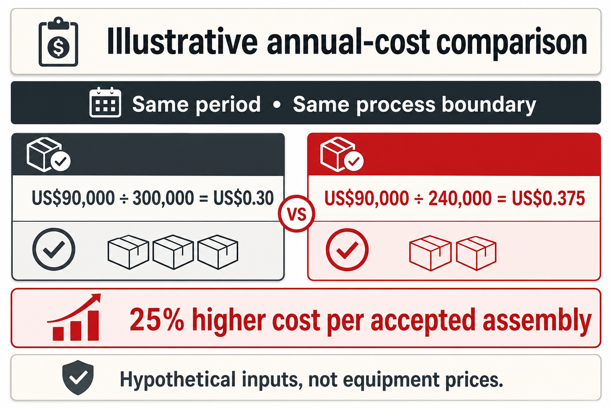
Compare costs to accepted assemblies for the same period and for the process boundary. Include annualized equipment cost, assigned labor, consumables, maintenance and the quality costs allocated to the operation. The purchase price is less important if a feeder requires frequent adjustment or if the station can’t produce the required output of good product.
University of Maryland’s yielded-cost research shows that the costs associated with each good assembly must be considered, and both upstream and downstream effects must be analyzed. For practical quote comparison, the cost boundary must be defined first. Rejected material must not be charged twice, and the cost ratio must not be divided by yield again if its denominator already counts accepted parts.
Suppose an illustrative annual station cost is US$90,000 and the station delivers 300,000 accepted assemblies in that year. The calculation is US$90,000 ÷ 300,000 = US$0.30 per accepted assembly. If the same annual cost supports only 240,000 accepted assemblies, the figure becomes US$0.375, a 25% increase. That sensitivity can change a purchasing decision even when the machine invoice stays unchanged. The plant manager may prefer extra capacity, while the finance manager needs justification that the extra capacity will be used. Ask both teams to agree the volume scenario, the labor actually redeployed and the costs that remain when output falls.
A unit-cost ratio is merely one aspect of a complete investment appraisal. Uncertainty and discounted cash flows are also included in NIST’s manufacturing investment appraisal guidance. If exposure to scrap or warranties is a concern, extend the comparison using the plant’s quality-cost records. Savings that are speculative in nature shouldn’t be included in the cash benefits of an investment proposal.
At US$90,000 per year, reducing accepted output from 300,000 to 240,000 assemblies raises unit cost from US$0.30 to US$0.375. Those illustrative numbers show why process automation needs a shared demand assumption. Assess productivity through accepted output before paying for manufacturing technology intended to increase efficiency.
Give Suppliers a Sample-Trial and Quotation Brief
A quotation brief should contain parts and process limits as well as acceptance evidence for pricing. Ask each manufacturer to identify exclusions, buyer-supplied items, and trial assumptions. For turnkey screwdriving solutions, include utilities, controls, and safe recovery and line interfaces as well as the feeder and screwdriver and fixture.
Copy the following map into the inquiry to simplify quote comparison. Assign an owner to each measurement. This can be used to discuss a custom assembly machine without assuming that every supplier’s automation solutions include the same tooling or data package.
| Quote item | Measured input | Hidden constraint | Evidence owner |
|---|---|---|---|
| Fastener family | Drawing dimensions in mm | Mixed lots or unstable feeding | Procurement: approved sample lots |
| Joint specification | Torque in N·m; angle where required | Friction or thread damage | Quality: validated process limits |
| Part location | Datum and tolerance in mm | Operator correction hidden in a demo | Engineering: fixture trial |
| Accepted-part takt | Seconds per accepted assembly | Only the drive stroke was timed | Production: complete cycle record |
| Refill and changeover | Minutes per event; events per shift | Manual work reduces availability | Production: observed changeover |
| Tool service | Minutes per bit change | Access or recalibration delay | Maintenance: service demonstration |
| Utilities and layout | Supply voltage, air pressure, footprint in mm | Plant supply or access does not fit | Integrator: approved installation drawing |
| Result handling | Records per part; retention period | Lost identity or blocked downstream release | Controls and quality: export/recovery test |
| Commercial boundary | Annual cost and accepted parts per year | Excluded qualification or support | Finance and purchasing: same-scope comparison |
Safe jam clearing should be procedure based, with a demonstration. Hazards related to stored energy and unexpected restart are among the maintenance hazards identified by OSHA’s robot guidance. The integrator should be required to document isolation and recovery procedures for the entire application and for all equipment, including equipment used to actuate clamps and the automatic tool. A plan that relies on reaching past safeguards to clear a feeder shouldn’t be accepted.
Do
- Send production screws and mating parts.
- Agree repeated good-part and fault trials.
- Request result exports and recovery evidence.
Don’t
- Substitute a feeder demonstration for assembly acceptance.
- Count every commanded cycle as a good part.
- Assume a controller recipe changes physical tooling.
A proposed 20 s assembly takt is incomplete without product mix, refill frequency, and acceptance conditions. Include those terms in the same quotation brief with torque and traceability. The supplier will then be able to explain which operations will fit inside 20 s, and which losses will require additional capacity to be provided.
Industry Outlook: What Is Changing in Screwdriving Specifications?
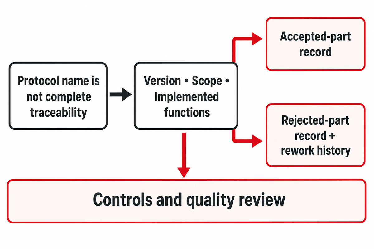
Current screwdriving specifications require clearer integration and data boundaries. Many of the systems being integrated exchange more information with the plant controls. Buyers should request to see actual part release results and the information the controller exports. Including an industry standard in the specifications, without clearly defining the version, scope and the functions that have been implemented, is of little value.
The published version of the OPC specification relies on the base model of a joining system for shared structures. This now provides purchasers with the means to discuss items like tools, results and part association. It doesn’t mean every automatic screwdriving product implements every optional field, nor does it mean that a separately named Open Protocol interface is exchangeable with OPC UA.
ISO 10218-2:2025 addresses industrial robot applications and robot cells. Ask the integrator which applicable requirements govern the complete installation and what validation evidence will be delivered. A robot component’s documentation does not establish conformity of the final fastening station. The scope also differs from ISO 5393’s tool-performance testing.
There’s reported commercial interest in more detailed tightening data. In ASSEMBLY’s December 2025 manufacturing outlook, Fein manager Doug Hohenstein described increased requests for wireless data collection, including non-safety-critical work. That is one supplier’s observation, not an industry growth forecast. The question is, will the record help make a quality decision or would it just be an unnecessary extra file?
A bidder should submit one complete accepted-part record and one rejected-part record, including any rework history, for a four-joint product. The examples should be reviewed by the control and quality teams at the plant. This small exercise provides the plant’s controls and quality teams the opportunity to discuss actual data examples before creating connections to controllers and factory-floor software.
Key takeaway
Specify automated screwdriving around accepted assemblies: a validated joint, a measured complete cycle and a result record tied to release. Select the feeder, tool and robot against that requirement.
Practical Questions Before Automating Screwdriving
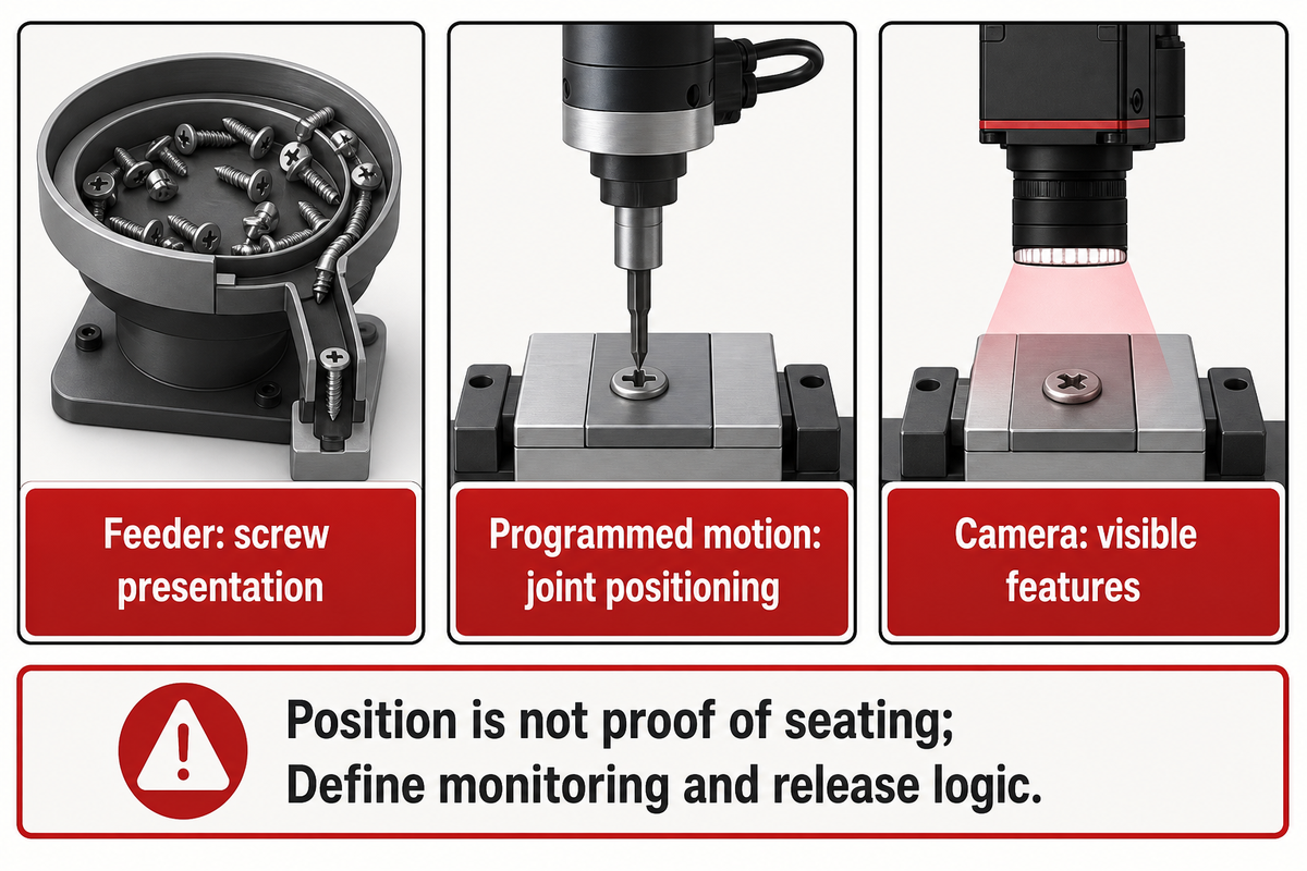
Screw-driving equipment names describe various scopes, so translate each offer into a clear sequence of operations. The important elements at the quotation stage for the best practices are concrete: what feeds the screw, what controls the joint and what releases the part. The following answers address common equipment and interface questions.
What is an automatic screwdriver called?
Common names include automatic screwdriver, tightening spindle and screwdriving system, depending on scope.
A supplier may use “automatic screwdriver” for the powered tool and controller, while “screwdriving system” may also include feeding and motion hardware. Define the supplied equipment in the quotation. Ask whether the offer includes part fixturing, screw presentation, joint monitoring and release logic. Product naming alone cannot establish how much manual handling remains.
What are CNC screwdriving machines?
These machines use programmed positioning to bring a screwdriver to specified joint locations.
A programmable gantry or similar motion platform can move the tool between stored coordinates. Feeding, joint access and tightening control still need separate qualification. Check positional capability against the actual fixture and part tolerances, then time the full assembly. A coordinate program does not verify that a screw seated correctly, and it does not remove the need for appropriate safeguards.
Where is automated screwdriving used?
Applications include electronics housings, automotive parts and other assemblies with repeatable threaded joints.
Suitability depends on access, part stability, fastener presentation and the joint specification. Repeated screw locations can justify dedicated tooling, while frequent product changes may favor a more configurable layout. Low-volume or variable work may suit an assisted station. Compare the whole process, including operator loading and inspection, rather than using the industry name as a selection rule.
Can the robot start and stop the screwdriver through its controller?
Usually this is possible with compatible interfaces, but the full command and result sequence must be defined.
Ask for the supported signals or communication protocol, the ready and busy states, completion result and fault response. The controls must also define what happens after interrupted power or a lost result. A start command alone is not enough to authorize part release.
Can a camera replace torque monitoring?
A camera can inspect visible features; it cannot directly establish tightening torque or internal clamp load.
Vision may help confirm screw presence, head position or the correct product variant when lighting and access permit. Select it for a defined inspection task. Where the joint specification requires tightening measurements, retain the appropriate tool monitoring and validate how both result streams affect acceptance.
Preparing an automated screwdriving request? Send ZEUEE the assembly drawing, screw samples, joint limits, and the target accepted-part cycle. Using the discussion on fastening-cell integration, define the scope of the sample and quotation, or request a project review.
Related Engineering Guides
- Planning the wider robot-cell interfaces
- Specifying a dedicated assembly machine
- Setting inspection tasks and acceptance limits
- Defining finished-product test coverage
References & Sources
- Gervasi et al.: Manual assembly and human-robot collaboration, 2023.
- Duarte et al.: Benchmarking human-robot collaborative assembly tasks, 2024 preprint.
- Becker and Sandborn: Using Yielded Cost as a Metric, 2001 abstract.
- NASA: Torque-tension effects of lubricants and threaded inserts.
- ISO 5393:2017: Public tool-performance testing scope.
- ISO 10218-2:2025: Industrial robot applications and robot cells.
- OPC 40450-1: Joining Systems, Base and OPC 40451-1: Tightening Systems.
- NIST: Assembly Performance Metrics and Test Methods.
- NIST: Capital Investment Analysis.
- ASQ: Cost of Quality.
- OSHA Technical Manual: Industrial Robot Systems and Industrial Robot System Safety.
- ASSEMBLY: Error-Proof Screwdriving, 2021 and U.S. Manufacturers Make Big Plans in 2025.
WHY WE WRITE THIS
About ZEUEE Engineering Insights
ZEUEE shares technical guides based on real automation project experience. Since 2005, we have designed and manufactured non-standard automation equipment for connector assembly, wire harness production, robotic lines, vision inspection, and smart factory upgrades.
Founded in 2005
20,000 m² production base
120+ specialists
150+ R&D patents
ISO9001:2015 certified