Get in touch with Zeyu lntelligent Industrial Company

Fiber Optic Connector Assembly Machine: Scope and Output


A Fiber Optic Connector Assembly Machine performs functions such as automating connector parts, terminating an optical fiber inside a ferrule, or coordinating several production stations. This guide focuses on equipment scope and accepted output: how station occupancy, shared resources and product matching change useful capacity. Clarifying that boundary first prevents a quick mechanical operation from being mistaken as the output of a complete, tested fiber optic cable assembly.
Updated October 2026 · By Cherry
Process at a glance
- Product: connector parts, terminated ends or finished cords.
- Route: adhesive and polish, mechanical splice or fusion splice-on.
- Quality: surface condition, geometry and optical performance.
- Capacity unit: accepted connector ends per defined production period.
A Fiber Optic Connector Assembly Machine performs a defined part of connector production. The termination route determines the stations required. Useful output counts ends that pass the agreed production tests.
Key points
- A clean end-face image and a low-loss optical connection are different measurements.
- Pre-polished connectors can use mechanical or fusion attachment.
- Batch occupancy can matter more than the longest individual waiting time.
- Four accepted ends are needed for a duplex cord with separate connectors at both ends.
What Does a Fiber Optic Connector Assembly Machine Do?
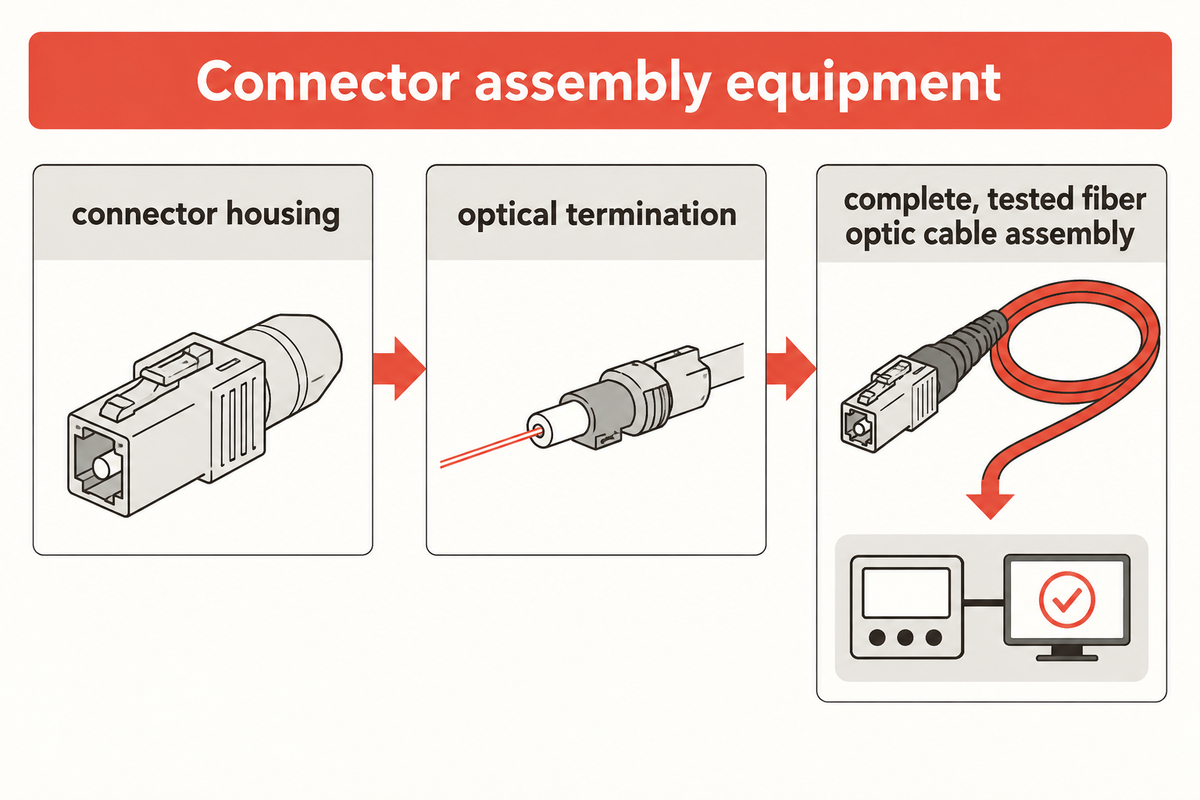
Connector assembly equipment feeds, positions and joins specified components under a controlled sequence. Its supplied scope can stop at a connector housing, continue through optical termination, or cover a coordinated line. The output description must identify the completed product and the operations still performed elsewhere in the factory.
How does a fiber optic connector assembly machine work?
A machine uses fixtures to locate parts, actuators to perform the joining operation, and controls to verify the sequence. A mechanical station might assemble a spring and housing around a ferrule. Optical termination adds fiber preparation and attachment; an adhesive route then needs curing and polishing before final checks.
That distinction changes how production is planned. An automatic feeder can assemble connector shells quickly while the downstream polishing machine waits for a suitable batch. The optical interface still needs its own process control. The Fiber Optic Association’s connector termination reference separates adhesive termination, factory-prepared interfaces and splice-based attachment.
Where Do Fusion Splicers and Prepolished Connectors Fit?
Fusion splicers join glass fibers. Prepolished connectors, however, already have a finished mating interface. The incoming fiber can attach to that interface using a mechanical splice or a fusion splice to a short pigtail. Therefore, prepolished describes the interface, not the attachment method.
For FTTH installation, a field assembly connector attaches at the installation location. Some fast connector designs use an internal fiber stub and index-matching gel. A quick assembly connector still needs compatible fiber preparation and handling. The FOA explanation of splice-on connectors describes both mechanical and fusion varieties.
Consider a maintenance team replacing two LC ends on an installed cable. The team needs a termination tool set that matches the chosen repair route, access to the damaged cable, and a means of assessing the repair. A factory producing repeated orders has a different problem: it must control preparation, material identity, batch movement and testing over a whole shift. Purchasing a compact field kit may solve the repair. Expanding production calls for a route that keeps work moving between stations. Treating both jobs as the same “connector assembly” task hides the equipment, and labor required to do so.
Scope rule: A two-end repair and a continuous production order share an optical interface, but their equipment boundaries differ. Identify the incoming and outgoing materials before comparing cycle times; a housing assembly cycle ends before the optical termination route has even begun.
Match the Assembly Process to the Connector Family
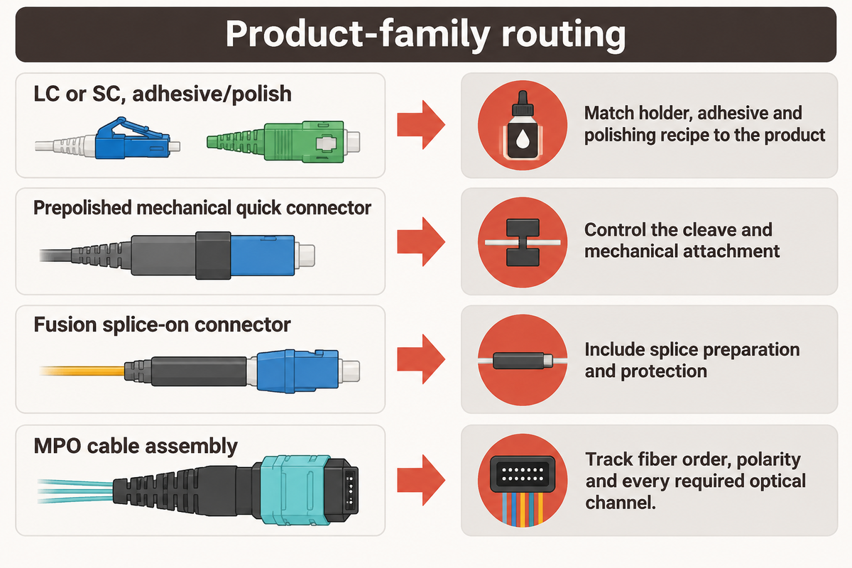
Connector family members differ in holder, fiber handling and measurement designs. LC and SC use individual cylindrical ferrules, while MPO places multiple fibers in a rectangular array. A family change can therefore alter preparation and test workload as well as the part held in the machine’s fixture.
The FOA Connector Identifier lists a 1.25 mm ferrule diameter for LC and 2.5 mm for SC. Those dimensions explain a tooling difference; they aren’t a complete compatibility specification. Housing geometry, cable construction and the required polished interface also belong in the recipe.
| Product | Process feature | Planning consequence |
|---|---|---|
| LC or SC, adhesive/polish | Fiber bonded inside an individual ferrule | Match holder, adhesive and polishing recipe to the product |
| Prepolished mechanical quick connector | Incoming fiber meets a factory-finished stub | Control the cleave and mechanical attachment |
| Fusion splice-on connector | Incoming fiber joined to a factory-terminated pigtail | Include splice preparation and protection |
| MPO cable assembly | Multiple fibers terminate in one array | Track fiber order, polarity and every required optical channel |
Singlemode and multimode fiber types also impact optical test set up. A single-mode APC interface has a finished angle; a PC interface uses a contact surface with a different end-face form. The mount has to locate the correct interface. Having a matching outer shell doesn’t indicate that a holder and recipe are adequate for the part.
A connector manufacturer’s assembly instructions remain the operating instruction for that connector. The tooling discussion in Cabling Installation & Maintenance’s polishing feature explains why kits and consumables can differ even within one connector style. Its 2005 field procedures shouldn’t be copied as a current factory recipe.
Counting rule: A simplex cord with a connector at each end has two physical connector ends. A duplex cord using separate LC connectors has four. An MPO trunk can have two physical ends and many optical channels. When assigning test time and planning a family change, keep these counts separate.
Record Station Occupancy Before Sizing the Machine
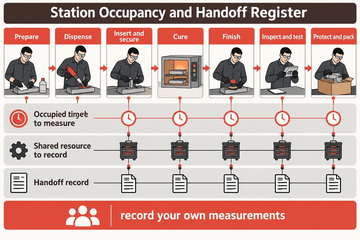
An epoxy-polish assembly process secures prepared fiber in a ferrule, cures the adhesive and finishes the mating face before checking the result. Automation can cover selected operations or connect several stations. The work is grouped into seven planning stages, with the connectors and adhesive instructions setting the detailed recipe.
Station Occupancy and Handoff Register
| Operation | Occupied time to measure | Shared resource to record | Handoff record |
|---|---|---|---|
| Prepare | Preparation plus loading time per end | Operator attendance and preparation tools | Prepared length, product identity and ready time |
| Dispense | Full dispensing and reload cycle | Dispenser and operator shared with other work | Adhesive lot, working-life limit and arrival time |
| Insert and secure | Assembly plus loading time per end | Insertion fixture and operator attendance | Part identity and completion time |
| Cure | Full occupied batch cycle | Usable cure positions and tray circulation | Batch identity, load time and release time |
| Finish | All polishing passes, loading and fixture return | Polisher, fixtures and operator attendance | Recipe identity, fixture release and ready time |
| Inspect and test | All required channels, directions and repeat visits | Camera, interferometer, test set and shared operator | Original results, repeat-work reason and accepted-end identity |
| Protect and pack | Protection, identification and packing time per cord | Packing operator and available materials | Matched-cord identity and release time |
This editorial planning register asks for measured inputs; it is not a machine specification. Use occupied time and shared-resource demand to test the capacity calculation. For the adhesive, finishing and inspection sequence itself, see our station-by-station connector assembly process guide.
Preparation removes a specific polymer coating or buffer. It doesn’t remove the glass cladding. That detail matters because a damaged optical fiber may survive handling and fail later in the route. Adhesive working life and cure conditions belong to the actual material instructions rather than a universal temperature copied from another assembly.
Cleaving also has two meanings. A precision fiber cleaver prepares a face for splicing or a prepolished mechanical interface. Removing the excess fiber from a cured adhesive connector precedes polishing and is a different task. Jim Hayes explains this distinction in Electrical Contractor’s 2003 cleaving article; its historical prices and yield estimates are not production assumptions here.
Fixture stability matters during polishing because the holder positions the ferrule against the finishing surface. Film selection, support and loading work in combination. More passes can remove more material without producing the required geometry. Keeping the recipe tied to the connector drawing makes a process change traceable when the final result moves.
Process rule: A factory can group operations, but the records must still connect the prepared fiber, adhesive batch and polishing recipe to the tested end. Combining stations changes handling; it does not remove the physical work or its quality checks. Record occupied time, shared resources and handoff identity before comparing station rates.
Why End-Face Inspection, Geometry and Loss Tests Differ

An end-face inspection assesses the condition of a surface, and a geometrical measurement assesses the shape of an interfacial contour. Optical testing assesses power transmitted or reflected under defined arrangements. A reliable production decision relies on the combination of these applicable checks. A surface photograph cannot provide the same information as an optical performance measurement.
“Visual inspection is in addition to, and does not replace measurement of performance parameters such as attenuation and return loss”
A ‘visual finding’ is used to hold the part for cleaning and reinspection. Final disposition is determined by optical performance and applicable acceptance criteria. The same IEC public summary says visual failure alone is not sufficient to reject a connector. A factory’s ‘process hold’ and a ‘final product rejection’ are different decisions.
For spherical PC/APC ferrules, IEC 61300-3-47 describes interferometric end-face geometry measurement. Rectangular multifiber geometry has a separate method. A normal inspection image does not directly replace the measurement of curvature, fiber position or other required geometry attributes.
Optical results need a pairing definition too. IEC 61300-3-4 addresses attenuation methods; IEC 61300-3-34 addresses the statistical distribution and mean attenuation of randomly mated connectors. Passing against a designated reference connector answers a different question from random-mating performance. Record the method with the result.
Consider a quality engineer seeing a rise in visual failures after a fixture change. Cleaning and reinspection separate loose contamination from persistent marks. However, some marks remain. Geometry measurements then show whether the mating surface has moved outside the product’s specified form. Optical checks can provide an assessment of the connection under the agreed reference arrangement. If the results of the optical checks don’t agree with the results of the geometry measurements, changing the camera threshold to address the discrepancy wouldn’t address the root cause of the problem. The engineer can compare the affected lot with earlier production, inspect the fixture and preserve the original readings. Because each check is designed to evaluate a different part of the problem, the approach of the investigation is to respond to the fault that was observed rather than address the station that first indicated a problem.
Initial production tests also differ from environmental qualification. IEC 61753-1 relates performance categories to tests, severities and service environments. A production pass does not establish long-term environmental performance. Detailed witnessed acceptance belongs in our optical connector line acceptance checks, rather than being repeated as a second acceptance manual here.
Measurement rule: Four accepted LC ends become useful duplex-cord work only when their identities and test basis remain linked. Record optical arrangement and all checks with end count. An image, a geometry result and a loss value each describe a different aspect of the product.
Count Good Connector Ends Before Quoting Output
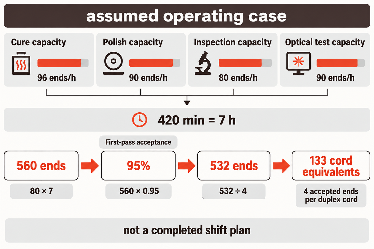
Good-end capacity is based upon one unit of one product and one unit of time. Then, consider limiting resources and first-pass acceptance. Connector ends, complete cords and optical channels require different counts. There’s also a difference between the capacity ceiling for steady-state conditions and the actual quantity a finite shift can complete and release.
Good-End Capacity Ledger
The Good-End Capacity Ledger transforms station loading into first-pass accepted ends, and maintains finished-cord matching and release requirements.
Example: Assume a 480-minute shift with 60 minutes of scheduled stops, leaving 420 minutes, or 7 hours. A cure batch holds 24 ends for a total of 15 minutes occupied cycle time. Polishing handles 18 ends in 12 minutes. Inspection takes 45 seconds per end; the required optical test package takes 40 seconds per end. All rates include loading and repeat visits needed for the operation, and exclude scheduled stops.
| Ledger entry | Calculation | Result | How to use it |
|---|---|---|---|
| Scheduled period | Given shift | 480 min | Keep the same period for every resource |
| Scheduled stops | Given allowance | 60 min | Subtract once |
| Net production time | 480 − 60 | 420 min = 7 h | Basis for the capacity ceiling |
| Cure capacity | 24 ÷ 15 × 60 | 96 ends/h | Use occupied batch time and usable positions |
| Polish capacity | 18 ÷ 12 × 60 | 90 ends/h | Count the full polishing route |
| Inspection capacity | 3,600 ÷ 45 | 80 ends/h | Lowest assumed station rate |
| Optical test capacity | 3,600 ÷ 40 | 90 ends/h | Include all required channels and directions |
| Steady-state start ceiling | 80 × 7 | 560 ends | Check shared-resource and scheduling limits |
| First-pass acceptance | Given combined production-test yield | 95% | Apply once to the same input cohort |
| First-pass accepted ceiling | 560 × 0.95 | 532 ends | Count passes before any rework recovery |
| Duplex cord equivalents | 532 ÷ 4 | 133 cord equivalents | Match ends to actual cords before reporting finished units |
The 15-minute cure cycle is longer than a 45-second inspection, yet its parallel batch capacity is higher. Alfieri and colleagues’ parallel-batching model separates batch duration and finite batch capacity. Its scheduling assumptions are a useful reason to examine loading and completion times rather than compare waiting times alone.
Starting with empty stations means some time must elapse before the first end reaches inspection. A partially filled last batch can finish after the shift. A shared operator, fixture shortages and rework can lower the result even further. The 532-end calculation is a first-pass, assumed resource ceiling in steady state, not a completed shift plan.
133 cord equivalents don’t necessarily mean 133 matched, completed cords. Some accepted ends may be from different cable lengths or lots. A failed end can strand other ends on the same cord. First-pass yield, final yield after rework and finished-cord release should therefore occupy separate production records.
Capacity rule: At 80 ends/h over 7 net hours, the assumed resource ceiling is 560 starts and 532 first-pass accepted ends at 95%. A completed order plan must include batch time, shared labor, and the matching of 4 accepted ends per duplex cord. Availability and yield deductions should be applied once.
Which Operations Should You Automate First?
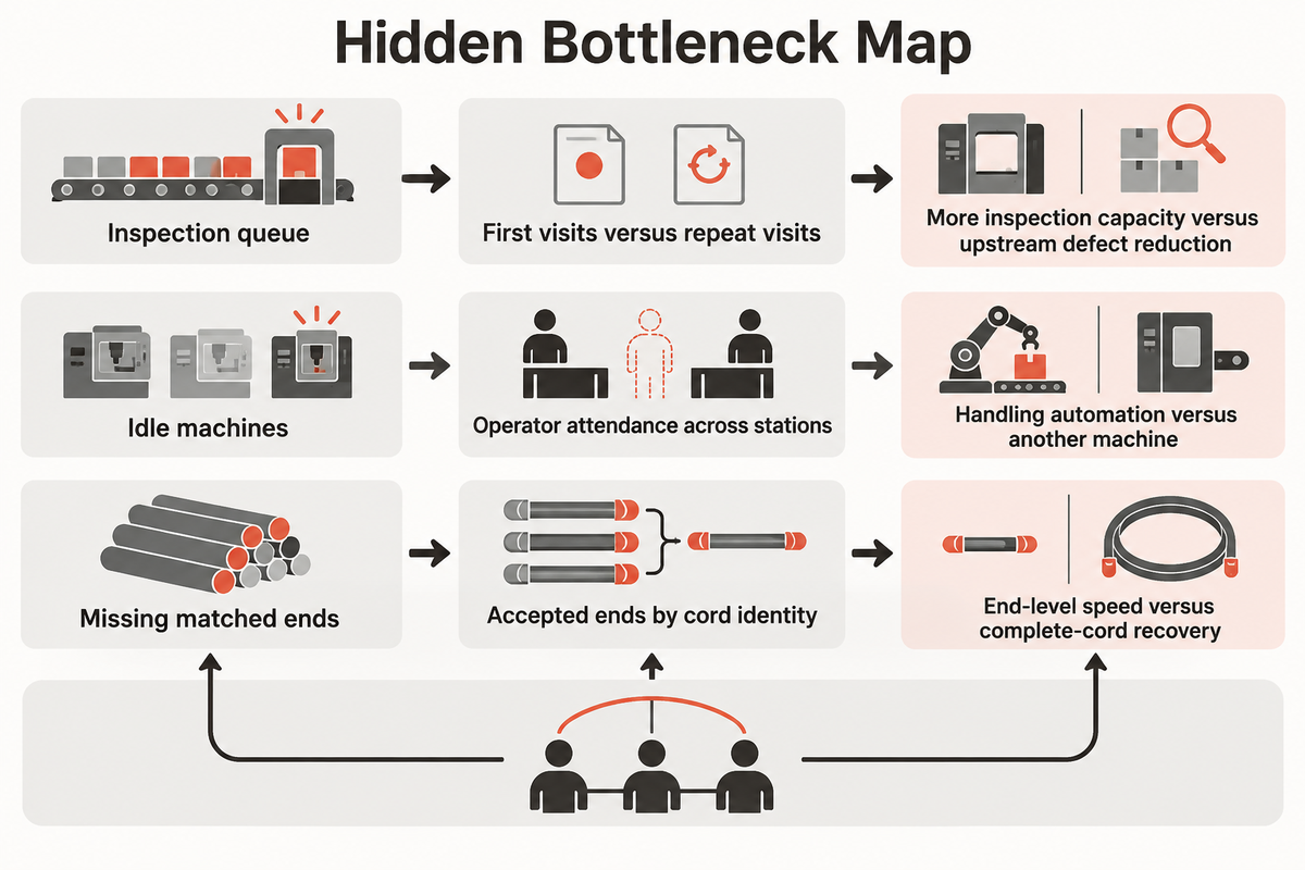
Automate the operation with the most significant constraint or recurring defect that limits useful output for the intended product mix. Compare machine occupancy to operator work and retest demand before selecting equipment. Improving a station with excess capacity may leave the finished-cord count unchanged and add unnecessary cost and integration work.
NIST’s research on multi-job production systems analyzes throughput and bottlenecks as functions of product mix. The work concerns automotive assembly, so it supplies a planning principle rather than a fiber connector benchmark. A mix of different optical products should have its own measured load model.
In the projected ledger, curing time alone doesn’t increase the 80 ends/h ceiling for inspection. Thus, a production manager may explore automation of the inspection process first. Quality may find that deficiencies in the dispensing process cause the repeated failures. Finance then has two different proposals: add inspection capacity, or reduce the extra work reaching inspection. The next useful measurement is the split between first inspections and repeat visits, followed by operator time for each route. That comparison can favor an earlier operation even though inspection currently has the lowest nominal rate. A purchase decision is made with respect to the Hidden Bottleneck rather than the longest obvious machine cycle.
Hidden Bottleneck Map
The Hidden Bottleneck Map separates the station that shows a queue from the resource or repeat work that creates it.
| Observed constraint | Measure next | Decision changed |
|---|---|---|
| Cure queue | Usable positions and occupied batch time | More positions versus a different loading schedule |
| Polish queue | Full-route occupancy and fixture circulation | Extra polishing capacity versus fixture availability |
| Inspection queue | First visits versus repeat visits | More inspection capacity versus upstream defect reduction |
| Test queue | Channels, directions and reconnections per product | Test handling versus an inappropriate unit assumption |
| Idle machines | Operator attendance across stations | Handling automation versus another machine |
| Changeover losses | Recipe changes by actual order sequence | Batch grouping versus dedicated equipment |
| Missing matched ends | Accepted ends by cord identity | End-level speed versus complete-cord recovery |
| Rework congestion | Reason-coded repeat load | Root-cause correction versus added retest capacity |
| Packing backlog | Completed product waiting for protection and identification | End-of-line handling versus faster upstream work |
Process definition should precede vendor comparison. Once the constraint and product family are clear, selecting an optical connector line manufacturer becomes a separate sourcing decision with a defined scope.
Key takeaway
In the assumed 80 ends/h inspection case, faster curing adds no steady-state output until the inspection load or capacity changes. Measure repeat work and shared labor before choosing the next automated operation.
Trace Common Defects Back to Their Process
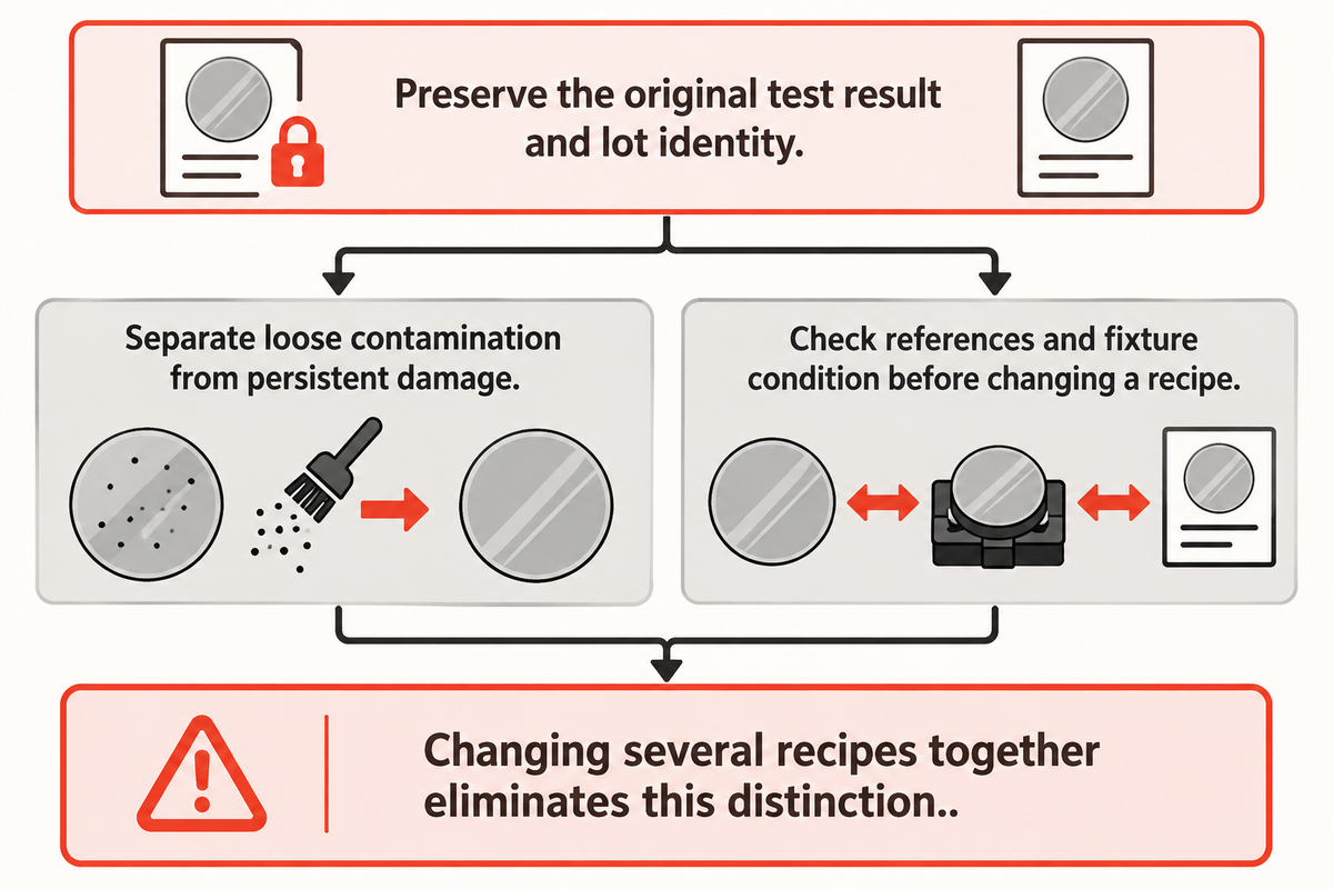
Defect triage begins by separating the part’s condition from the measurement setup and follows through to preparation, bonding, finishing, and handling. Changing several recipes together eliminates this distinction. Preserve the original result and compare a known reference before adjusting an operation that could affect the rest of the lot.
Why is my fiber optic connector assembly machine not working?
There are several possible causes for an optical failure, including feeding, seating, and condition of the material, as well as the test and polishing arrangements. The first step is to check the station and the defect observed at the stop. For optical failures, inspect and clean the mating interfaces, then compare the measurement setup before changing adhesive or polishing settings.
A NIST study of connector-induced power-meter offsets demonstrated that connector and detector reflection properties can affect readings. The 2006 experiment explains a mechanism to consider; its measured variation isn’t a tolerance for current production equipment.
Overpolishing deserves a separate check. Mike A. Reed’s technical article on overpolished connectors explains how glass can become recessed relative to a ceramic ferrule. It supports investigating material removal, rather than assuming more polishing always improves an end face. Use the qualified product recipe for any rework.
Do
- Preserve the original test result and lot identity.
- Separate loose contamination from persistent damage.
- Check references and fixture condition before changing a recipe.
Don’t
- Keep polishing a failing end without checking geometry.
- Count a retest as a new manufactured end.
- Combine several process changes in one investigation.
Operators must recognize fiber damage, maintain clean handling and know when to stop the process. A camera can classify an image, but the response still needs a defined route for cleaning, reinspection or process investigation. Good records allow quality to separate a material lot issue from a worn fixture.
Fault rule: A duplex cord has four physical ends that can enter investigation separately. Keep each failed end tied to the cord and its original result; replacing the record with a retest pass hides first-pass loss and prevents the team from locating the operation that created the extra work.
Industry Outlook: Keep Geometry Methods Current
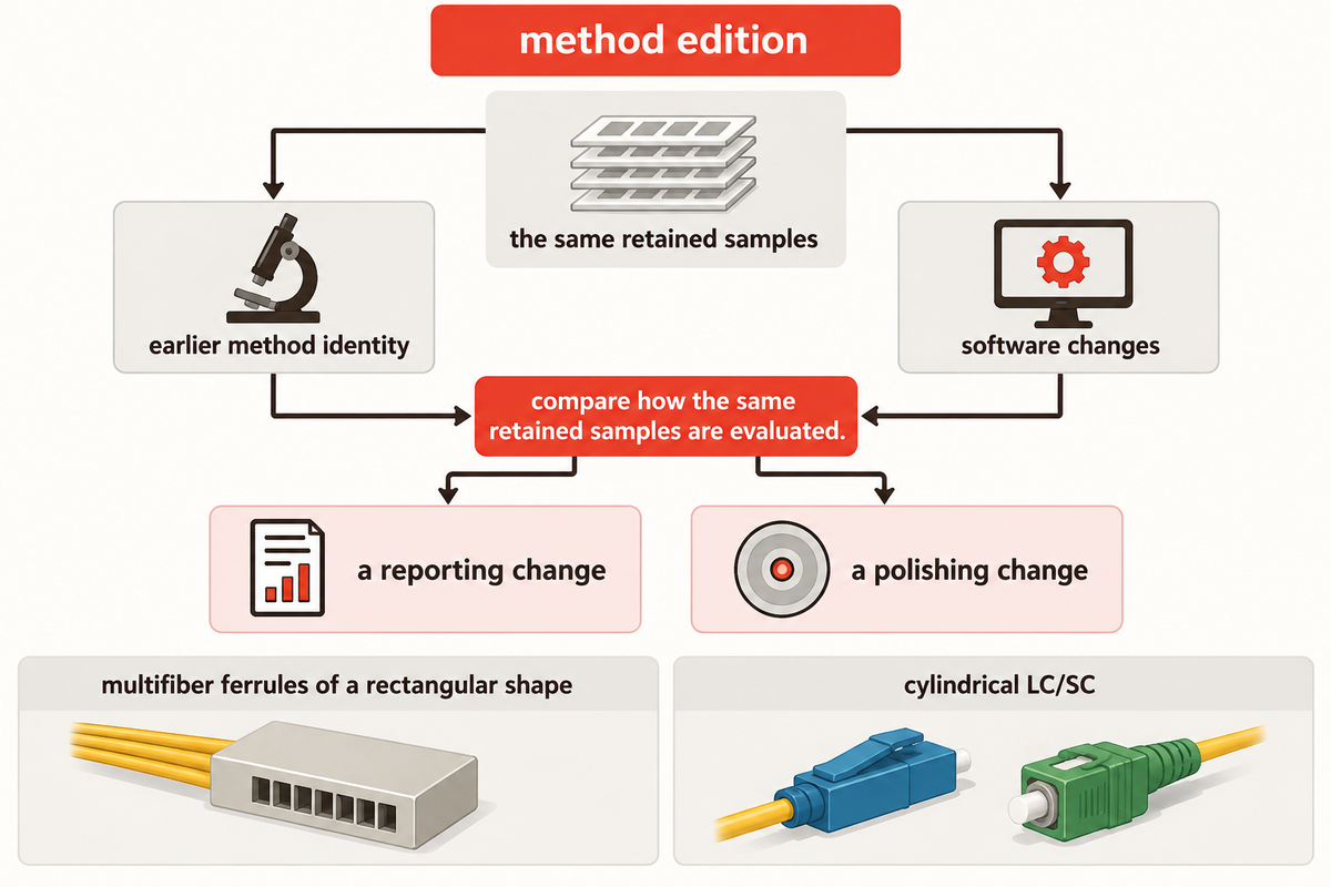
In 2026, method identity becomes a practical integration issue. A factory adding fiber counts or changing measurement software needs reports that identify the connector family, recipe and method edition. However, updating those documents allows customers to distinguish a change in the definition of the method from a change in the manufactured product.
The IEC catalogue dates IEC 61300-3-30:2026 to 27 July 2026. Its published change list adds regions of interest supporting MT-16 and MT-32 and geometry-limit parameter tables for 16-, 24- and 32-fiber ferrules. The method is concerned with multifiber ferrules of a rectangular shape. Measurements of cylindrical LC/SC follow the appropriate method of cylindrical ferrules.
From the perspective of a production team, the key action is to relate the measurement recipe to the product drawing and reporting template. With the earlier method identity retained, compare how the same retained samples are evaluated when software changes; quality can distinguish a reporting change from a polishing change. Procurement can include the required method and supported product family in the integration scope without treating a newly published method as automatic qualification of the line.
This integration work includes utility and material flow. Keep the actual requirements for power and air at a station, the arrangement of fiber scraps, and the path from polishing to clean inspection and protected packing. Keep adhesive lots and prepared fiber identified. A clean finished interface loses its advantage if unprotected material moves through a dirty preparation area.
This route describes layout and control integration. A compact station that requires frequent manual loading may consume more operator attendance than a larger batch arrangement. The best layout to process a repeated single-family order may be different than a layout to process orders that include LC and MPO items. The type of order mix that you want to process determines station arrangement.
Integration Rule: Changing from a 16-fiber to a 32-fiber rectangular ferrule changes the array and number of channels managed. Retain geometry-method identity, channel records and material routing with recipe. A software update and a product change should be distinguishable in production history.
Frequently Asked Questions
Is a connector assembly machine the same as a fusion splicer?
A connector assembly machine and a fusion splicer perform different jobs, although a splice-on production route can use both.
A splicer joins prepared glass fibers. Connectorizing gives a cable a removable mating interface, with the required housing, retention and protection. A factory may polish that interface after adhesive bonding, or attach the incoming fiber to a factory-finished pigtail. The process boundary determines which equipment belongs in the route and which checks remain downstream.
Can a single line handle LC, SC and MPO connectors?
One line can serve multiple families when its tooling, handling and measurement systems support each defined product route.
LC and SC have different ferrule diameters, while MPO introduces an array of fibers in a rectangular ferrule. Holders alone do not address every change. Preparation, polishing, geometry measurement and optical channel handling also need the correct arrangement. Separate product recipes and a measured changeover sequence make the shared-line workload visible before production orders are scheduled.
Does a factory have to use epoxy for every connector?
No. Adhesive-polish, prepolished mechanical and fusion splice-on routes attach fibers in different ways.
The selected connector construction sets the route. A prepolished product has a factory-finished optical interface, so attaching the incoming fiber does not repeat that polishing operation. Mechanical attachment and fusion attachment then require their own preparation and protection. For an adhesive connector, the specified adhesive and cure cycle remain part of the process rather than optional steps.
Does visual inspection replace insertion-loss testing?
No. Visual inspection describes surface condition; insertion-loss testing measures optical transmission under a stated test arrangement.
Cleaning and reinspection address contamination. Persistent findings need the applicable geometry and optical checks, with final disposition following the specified performance and acceptance requirements.
Are connector ends the same as finished patch cords?
No. Connector ends count termination work; finished patch cords count complete assemblies that meet their release requirements.
A simplex patch cord has two connected ends. A duplex patch cord with separate connectors at both ends has four. An MPO trunk may still have two physical ends, even though each contains multiple fiber channels. Divide accepted end capacity by the appropriate end count only to obtain cord equivalents. Actual finished output also requires matching those accepted ends to the same cord, completing every required channel check and retaining the correct product identity. Reworked passes should remain distinguishable from first-pass acceptance so production and finance use the same output definition.
Are fiber optic connector assembly machines still used?
Yes. Connector manufacturing uses dedicated operations and automated stations, while field termination also uses portable tools.
A tool designed for simple and fast field termination of single fibers serves a different workload from a factory line. The application determines the equipment boundary.
What information belongs in the first process discussion?
Start with the connector drawing, termination route, product mix, accepted-output definition and target production period.
Include cable construction, polish type, fiber count, the optical test arrangement and the required production records. Describe the current queue and split first visits from rework. A measured operator workload helps separate machine time from attendance. If finished cords are the target, state their end count and how matching and release are recorded. That information gives the engineering discussion a concrete basis: the operation to automate, the products it must handle and the output that the surrounding process must sustain. It also gives finance a consistent unit for evaluating useful capacity.
Bring a Defined Process to the Next Discussion
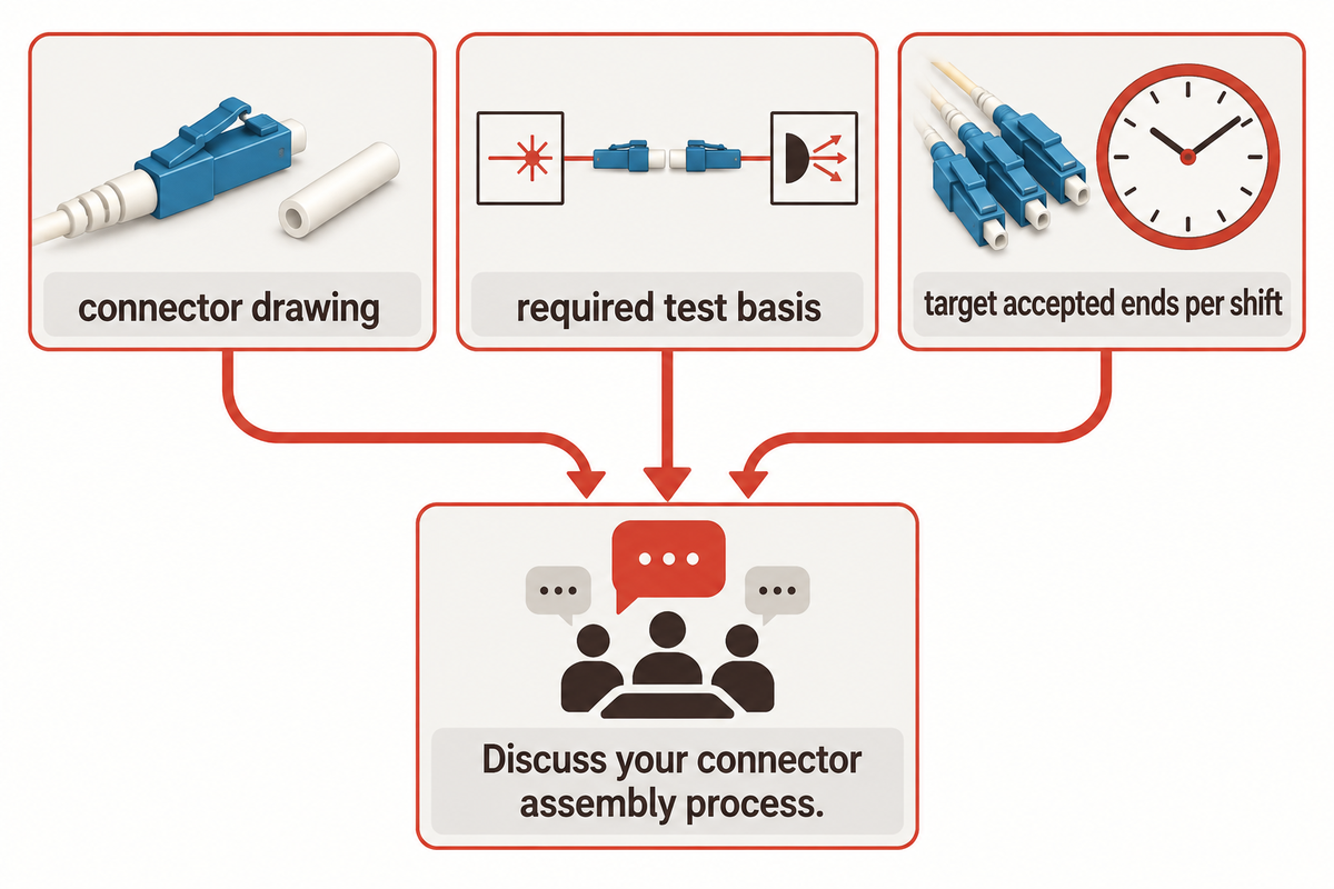
Use a process map to define the work, and then fill the capacity ledger with measured inputs from the order mix that’s intended. For an equipment project, review the fiber optic connector assembly machine solution, bring the connector drawing, required test basis and target accepted ends per shift to the meeting.
Discuss your connector assembly process
Published by ZEUEE engineering and manufacturing. This guide combines public technical references with a labeled capacity example; it doesn’t include case studies of customer factories. Product instructions and agreed acceptance standards govern production.
References & Sources
- Fiber Optic Association: connector termination reference
- Fiber Optic Association: mechanical and fusion splice-on connectors
- Fiber Optic Association: Connector Identifier
- Cabling Installation & Maintenance: Polishing to perfection, 2005
- Fiber Optic Association: adhesive/polish termination hints
- Electrical Contractor: Jim Hayes on cleaving, 2003
- International Electrotechnical Commission: IEC 61300-3-35:2022, visual inspection
- International Electrotechnical Commission: IEC 61300-3-47, spherical geometry
- International Electrotechnical Commission: IEC 61300-3-4, attenuation
- International Electrotechnical Commission: IEC 61300-3-34, random-mated attenuation
- International Electrotechnical Commission: IEC 61753-1, performance categories
- Alfieri et al.: parallel-batching scheduling model, 2020 preprint
- National Institute of Standards and Technology: product mix and bottlenecks, 2018
- National Institute of Standards and Technology: connector-induced meter offsets, 2006
- Cabling Installation & Maintenance: Mike A. Reed on overpolishing, 1995
- International Electrotechnical Commission: IEC 61300-3-30:2026, rectangular geometry
WHY WE WRITE THIS
About ZEUEE Engineering Insights
ZEUEE shares technical guides based on real automation project experience. Since 2005, we have designed and manufactured non-standard automation equipment for connector assembly, wire harness production, robotic lines, vision inspection, and smart factory upgrades.
Founded in 2005
20,000 m² production base
120+ specialists
150+ R&D patents
ISO9001:2015 certified




![Automated Screwdriving: Torque & Cycle Time [Guide]](https://zeueeauto.com/wp-content/uploads/2026/10/automated-screwdriving-featured-150x150.png)